Download presentation
Presentation is loading. Please wait.

1
Digital Control The s plane root locus design technique concentrates on two figures of merit: time to peak and percent overshoot. From these two figures of merit we determine values for the damping ratio and natural frequency. (See equations 5.14 and 5.16) In digital electronic we learnt how to transform from s plane to z plane. In this lecture we use another way for transformation called Ad Hoc (Pole/Zero) Mapping.
 In digital electronic we learnt how to transform from s plane to z plane. In this lecture we use another way for transformation called Ad Hoc (Pole/Zero) Mapping..")
2
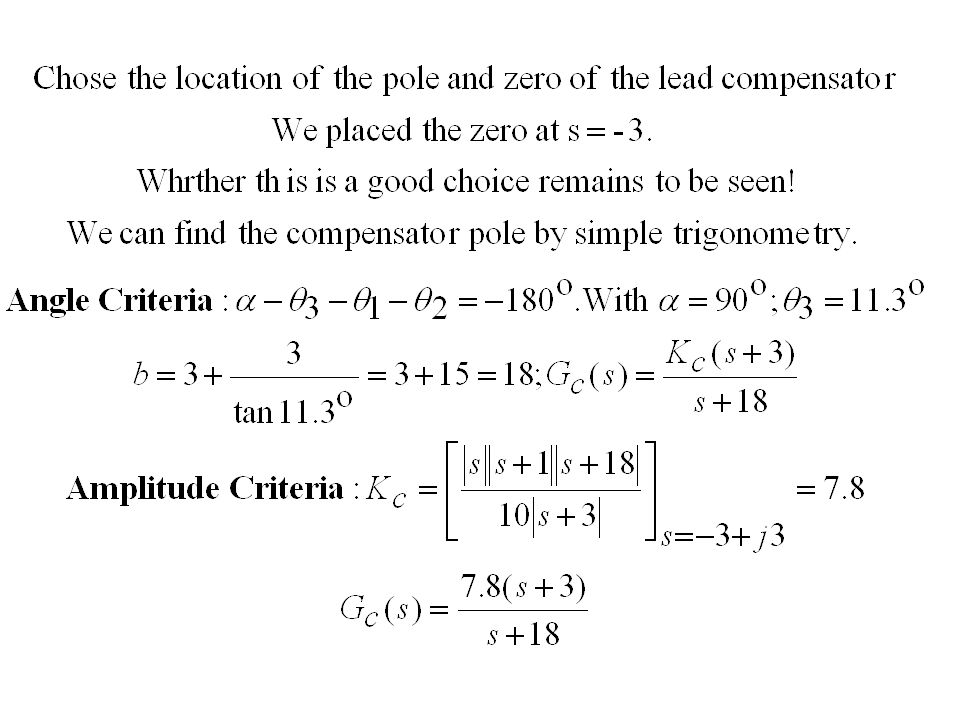
Lead Compensation Has the same purpose as PD compensator to improve the transient response. It consists of zero and a pole with the zero closer to the origin of the s plane than the pole. The zero of the lead compensator like the zero of the PD compensator reshapes a portion of the root locus to achieve the desired transient response. The pole influence the overall shape of the root locus but its impact on the portion being reshaped by the zero is minimal. A lead compensator can be implemented by opamps.

3
Example s s+1 s+a s+bs+b 11 22 33 Re (s) Im (s) -b-b -a-a0
 Im (s) -b-b -a-a0")
5
Lag Compensator Identical to PI compensator. Improves steady state accuracy. The pole of the compensator is close to the origin. The pole close to the origin is a near approximation to a perfect integrator.

6
The Ad Hoc (Pole/Zero) Mapping Translate all poles from s plane to the z plane using z = e sT Translate all finite zeros using z = e sT If the s plane transfer function has any zeros at infinity, place a zero at z = 0 for each zero at infinity. Select a gain G(z) so that
 so that.")
7
Example of Transformation

8
Design in the s Plane In this example, we may do the design ignoring the effect of the zero- order hold, and then redo the design to include its effect. We may ignore the effect of the zero-order hold, if the sampling rate is high enough.

9
-b-b -2 0 s+bs+bs+2 s+1 s 2 22 11 33

10
Choosing a Sampling Rate We say we require 10 samples per cycle of the output. Since the damped frequency at which the closed loop system will oscillate is 2 rad/, this yield a sample rate of 20 rad/s, or 3.18 Hz. Then the intersample period T is 0.314s. This is slow sampling rate. We will increase it to 10 Hz. We use bilinear mapping in order to map the compensator G c (s) to the z plane
 to the z plane.")
11
The Bilinear Mapping We usually map the lines of damping constant and natural frequency from the s plane to the z plane using the mapping z = e sT. Compensators can be mapped from the s plane to the z plane in variety of ways. The bilinear mapping is a frequent choice for mapping compensators from the s plane to the z plane. The usual choice for a is 2. For this choice of a, the bilinear mapping is the inverse of the trapezoidal rule for numerical integration (Tustin’s method).
..")
Similar presentations


 Dr. Imtiaz Hussain Assistant Professor>")
. + - + - + ->")


>")


>")

