Download presentation
Presentation is loading. Please wait.

1
Research in New & Renewable Energy Dr. Li Ran

2
Wind Power

3
Recent Studies in Wind Power Gearbox Wind Turbine Doubly Fed Induction Generator 4Q Converter Filter Grid DFIG Grid Fault Ride Through

4
Renewable Energy Networks Grid code sets out requirements for grid interconnection. Most current renewable generation systems are treated as “negative” load. Future systems MUST contribute to system frequency and voltage control. Grid interconnection usually “makes or breaks” a project. Development of many (ALL?) renewable energy converter systems have concentrated on the device itself without detailed thought of how to convert the power for grid interconnection. Future developments MUST consider the system as a whole – REQUIRES INTEGRATED SYSTEM APPROACH.
 renewable energy converter systems have concentrated on the device itself without detailed thought of how to convert the power for grid interconnection. Future developments MUST consider the system as a whole – REQUIRES INTEGRATED SYSTEM APPROACH..")
5
Grid Code - Example ● The value of grid-fault ride-through is increasingly appreciated. ● Grid code, e.g. Scottish Hydro-Electric Guidance Note A wind farm must remain connected under the following conditions depending on fault voltage reduction and registered capacity of wind farm. wind farm registered capacity voltage during fault <30 MW >=30 MW 0% July 2005 January 2004 15% before January 2004 ● The voltage refers to that on the transmission system (275 or 132 kV). Transformer impedance and fault infeed from the wind farm are likely to result in a higher voltage at generator terminal. ● Fault is cleared in 140 ms for 132 kV and 100 ms for 275 kV system. Backup clearance time can extend to 300 ms.
. Transformer impedance and fault infeed from the wind farm are likely to result in a higher voltage at generator terminal. ● Fault is cleared in 140 ms for 132 kV and 100 ms for 275 kV system. Backup clearance time can extend to 300 ms..")
6
Initial Control Idea – why can’t it work? stator voltage rotor voltage control irir fault

7
Recent Studies in Wind Power Gearbox Wind Turbine Doubly Fed Induction Generator 4Q Converter Filter Grid DFIG Grid Fault Ride Through

8
Feasibility Region with Proposed Control { super-synchronoussub-synchronous This plot says that the DFIG can successfully ride through a grid fault which brings terminal voltage down to 0.3 pu, even it initially operates at full speed.

9
Durham 30 kW DFIG Test Rig prime drive with programmable direct torque control DFIG XPC Targetbox real time system Filter Grid VARIAC 4Q conv

10
Laboratory verification 9.951010.0510.1 -2 -1.5 -0.5 0 0.5 1 1.5 2 ir-abc (pu) Time (s) 9.951010.0510.1 -2 -1.5 -0.5 0 0.5 1 1.5 2 ir-abc (pu) Time (s) Rotor current constrained by control Simulation Experiment
 Time (s) ir-abc (pu) Time (s) Rotor current constrained by control Simulation Experiment")
11
Grid Fault Ride Through ωrωr { Power tracking control D.C. link voltage control Configuration with direct-in-line converters

12
A Proposed Research Study on the transient behaviour of and interaction in an integrated machine-converter system, including - Transient FE modelling of machine (HTU discovered that the equivalent ckt model of a DFIG gives fault current that the equivalent ckt model of a DFIG gives fault current that is about 10% too low – ICEM 2004.); is about 10% too low – ICEM 2004.); - Transient thermal modelling of semiconductor devices; - Control of converters to satisfy machine and power system requirements. requirements. Objective: optimized design and control strategy.

13
Recent Studies in Wind Power Direct Drive (Gearless) Wind Turbines
 Wind Turbines")
14
The Nacelle of a Geared Turbine Generator Gearbox Drive Shaft Blades Pitch Mechanism Lightning Arrester Anemometer Mechanical Brake Hub Tower Yaw Drive

15
Turbine with Gearbox Epicyclic First Stage 3 spur gear stages High Speed Brake Generator 13 kN.m 1500 rpm Turbine Blades Hub with Pitch control Mechanism Main Bearings Low Speed Brake 1 MN.m 20 rpm 2 MW rated power

17
Vernier hybrid machine for direct drive wind turbine Flux switching machine Incorporates magnetic gearing High shear stress High force/torque at low speed Low power factor

18
Four-pole, three-phase, prototype

19
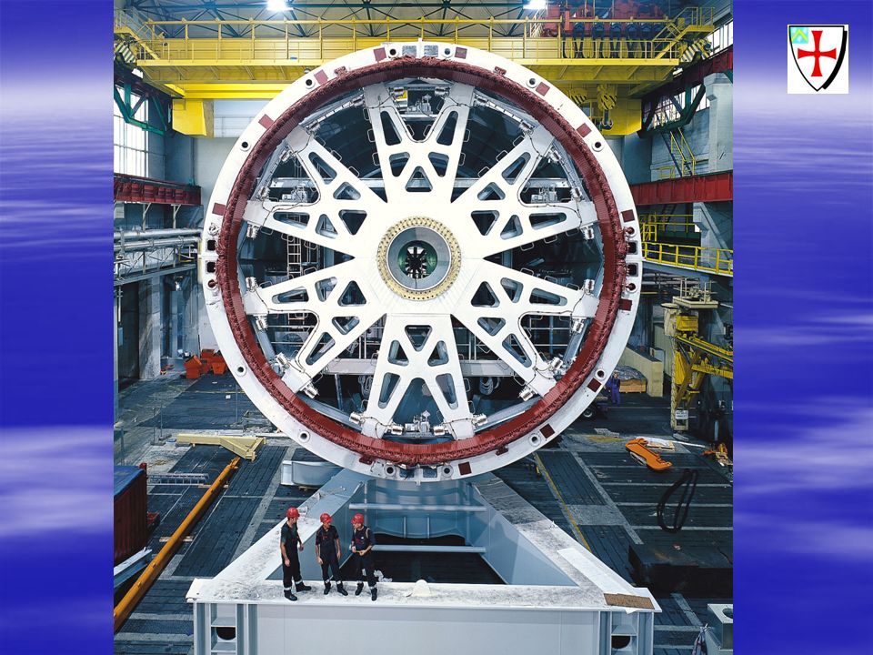
The SLiM Concept (from EGL) Three key aspects Large diameter using pre-tensioned spokes and pre-compressed rims Ironless stator avoids magnetic pull Permanent Magnet Rotor
 Three key aspects Large diameter using pre-tensioned spokes and pre-compressed rims Ironless stator avoids magnetic pull Permanent Magnet Rotor")
20
Ironless Stator Version Rotor steel rim Large Rare Earth Magnets Stator non-metallic rim Stator coils Magnet flux pattern

21
Spoked Lightweight Direct Drive Wind Machine (SLiM) Evolving Generation Ltd
 Evolving Generation Ltd")
22
Initial Power Conversion Arrangement Stator coils Inverter module Output to grid

23
EGL

24
On Going Research Research on power conversion and control Schemes trying to achieve Fault tolerant operation Air-gap support Transformerless grid interface that satisfies grid codes Low cost 100% rated converter Integration of PE and machine coil?

25
On Going Research condition monitor Voltage regulator Auxiliary power pick up Main output coils D.c.-d.c. converter Brake resistorH-bridge Cascade in series with other bridges in the same phase Bypass switch Optical gate signals & Thyristor and diode rectifier Figure 1: A possible module design

26
On Going Research

27
Circuit Diagram Chopper cut out speed: 9m/s Current at cut out: 3A Generator cut out (using circuit breaker): 18.5m/s Generator cut out current: 17A Maximum high frequency ripple current: 3A Maximum transistor current: 3A Maximum diode current: 17A
: 18.5m/s Generator cut out current: 17A Maximum high frequency ripple current: 3A Maximum transistor current: 3A Maximum diode current: 17A")
28
Converter design: system simulation

29
Tracking Simulation

30
Annual Energy Capture Average wind speed (m/s) Annual Energy Capture (kWh) Battery Part Converter Full Converter Maximum 5371451453454 6690762771779 71083114411681229 91848189119542520 Average wind speed (m/s) Partially rated converter Fully rated converter Increase from direct connection (kWh) Percentage increase Increase from direct connection (kWh) Percentage increase 58021.6%8222.1% 67210.4%8111.7% 7615.6%857.9% 9432.3%1065.7%
 Annual Energy Capture (kWh) Battery Part Converter Full Converter Maximum Average wind speed (m/s) Partially rated converter Fully rated converter Increase from direct connection (kWh) Percentage increase Increase from direct connection (kWh) Percentage increase %8222.1% %8111.7% %857.9% %1065.7%")
31
Wave Energy

32
Demonstration of Absorbing Wave Energy a b c d

33
Wave Energy Converters Shoreline devices Simple maintenance and grid connection cost of land intrusion Example: OWC Nearshore devices, typically 10-25 m deep, devices can be tight moored to the sea bed Deep water devices, slack moored to maintain geographical position only

34
Wave Energy Converters Terminator type Principle axis parallel to incident wave crests Waves are stopped as they reach the device Example: Salter Duck Attenuator type Principle axis perpendicular to wave crests Energy conversion by relative motion of parts of the device as a wave passes underneath Example: Pelamis Point absorber Oscillating body (next slide)
")
35
Concept of Direct Drive Wave Energy Converter Couple moving part direct to generator Remove intermediate mechanical systems Slow reciprocating motion

36
Wave Energy Wavegen Oscillating water column, Islay Ocean Power Delivery Pelamis, SRO contract for Machir Bay Teamworks Technology Archimedes Wave Swing

37
Direct Drive Wave Machine

38
3-phase ac/ac converter 3-phase ac/ac converter Power output - 300W per half phase dc link 150V new inverter, 800V dc link

39
Converter Power Current, I Voltage, V Power in =VxI Power out of Machine Into Converter

40
Direct Drive Machine Electrical Requirements At 1m/s, 100 kW, Force = 100 kN Conventional machines, = 20-30 kN/m 2 Transverse Flux Machines, = 200 kN/m 2

41
High force density electrical machines-problems High airgap closing forces Maxwell stress α B 2 Airgap closing force Force at zero current

42
High force density electrical machines-problems Low power factor High open circuit voltage (e.g. 60 volts) Internal resistance = 1.5 Ohm Expected short circuit current 40 A ? Expected power 2.4 kW ?
 Internal resistance = 1.5 Ohm Expected short circuit current 40 A . Expected power 2.4 kW .")
43
High force density electrical machines-problems Actual short circuit current 1.5 Amps Actual power approx. 3.3 W ! Require active rectifier

44
Low force density electrical machines Good magnetic circuit for high shear force is root of its problems Presence of iron in circuit No iron = poorer magnetic circuit No Maxwell stress Lower inductance Ironless / air cored

45
Cylindrical opposed rare earth PMs Coils not supported in steel Air cored tubular machine

46
Power Conversion Scheme 1 1’1’ 1 2’2’ 2 8’8’ 8 R R’R’ 1’1’ 1 2’2’ 2 8’8’ 8 Y Y’Y’ 1’1’ 1 2’2’ 2 8’8’ 8 B B’B’ R Y R,Y,B R ’,Y ’,B ’ ~700 V peak V and I: 370 V /phase 75 A Large coil resistance: by pass inactive coils

47
Power Conversion Scheme 2 e(t) L R control target: i(t)=|e(t)|/(2R) common d.c. link from other coils coil

48
Power Conversion Scheme 2 - coil EMF - coil current

49
Down Stream Power Conversion

50
Solar Power

51
Solar powered pump

52
Durham University Solar Powered Car

54
Power Systems

55
Grid Integration – HV/MV AC or DC ? 150kV dc cable to network Isolator Rectifier 123kV AC BUS Transformers Circuit breakers 41 kV rms AC Six-step inverters Isolators 50kV dc cables from generators

56
Summary Grid fault ride through - DFIG, Direct-in-line converter semiconductor device, machine modelling, control Direct drive wind power - Fault tolerance, air-gap support, grid interface, cost, integration Direct drive linear wave machine - Low voltage high current, energy storage, active damping Solar power Power systems

57
Discussion on Collaboration Fees Subsistence Visiting scholar Ph.D. studentship Industrial projects from China (local) Government research projects from China Application for China-UK or China-Europe projects
 Government research projects from China Application for China-UK or China-Europe projects.")
Similar presentations


 or distributed generation resources (DR) –Backup generation.>")


 machine can be used as a motor or as a generator. DC Machine is most.>")

