Download presentation
Presentation is loading. Please wait.

1
The Technological World
The Amazing World of Gears

2
Gear Theory What is the purpose of gears?
To increase torque and decrease speed To increase speed and decrease torque To change the direction of rotation by 90° To reverse the direction of rotation Torque : measures the tendency of a force to rotate an object about some axis

3
Gear Theory Regardless of what you do you will only ever have two main types of gears: Driving Gears and Driven Gears Driving Gears are connected directly to the power source and transfer the power to the Driven Gears. Driven Gears are in contact with the Driving Gears and either increase the torque or increase the speed.

4
Principles of Gearing When a small gear drives a large gear you are said to have a gear reduction. Where the driving gear would turn several times for only one turn of the driven gear. (Gear reduction would be used on a bicycle when going up hill) When a large gear drives a small gear you are said to have an overdrive. Where the driving gear would turn only once and the driven gear would turn several times. (Overdrive would be used when going downhill or on a straight road).
 When a large gear drives a small gear you are said to have an overdrive. Where the driving gear would turn only once and the driven gear would turn several times. (Overdrive would be used when going downhill or on a straight road).")
5
Principles of Gearing When two gears of the exact same size are in contact, it is said to be direct drive. Where there is neither a torque increase nor a speed increase

6
Principles of Gearing If you have an even number of gears in contact, regardless of their size, the last gear will always turn in the opposite direction of the first gear in the set. Example: If the top gear drives the bottom gear, the bottom gear will rotate in the opposite direction!

7
Principles of Gearing If you have an odd number of gears in contact, regardless of their size, the last gear in the set will always rotate in the same direction as the first gear in the set. Example: If the first gear rotates clockwise every odd numbered gear must also rotate clockwise.

8
How to determine Gear Ratio
To calculate gear ratio you must always use the following formula: Number of Teeth on the Driven Gear divided by the Number of Teeth on the Driving Gear. Example 1: If the driving gear has 8 teeth and the driven gear has 41 teeth, the ratio is said to be 5.13:1 41 ÷ 8 = 5.13 Example 2: If the driving gear has 32 teeth and the driven gear has 22 teeth, the ratio is said to be 0.69:1 22 ÷ 32 = 0.69

9
Sample Questions Question 1: If you have a driving gear with 13 teeth and driven gear with 54 teeth, what is the gear ratio? Answer 1: ÷ 13 = 4.15 The gear ratio is 4.15:1 (Read 4.15 to 1)
")
10
Question 2: If a driven gear with 72 teeth is being rotated by a driving gear with 96 teeth, what is the gear ratio? Answer 2: ÷ 96 = 0.75 The gear ratio is 0.75:1 ( Read 0.75 to 1)
")
11
Question 3: If you have 15 gears in mesh that are all of different sizes and the first gear in the set rotates counterclockwise, which direction will the last gear in the set rotate? Answer 3: Since you have an ODD number of gears the last gear in the set will turn in the same direction as the first. The size of the gears DOES NOT affect the direction of rotation.

12
How Gear Ratio Affects Output
If a gear ratio has a number numerically larger than 1 at the front of the ratio, you have a gear reduction Example 4 : 1 A gear reduction means that the speed of the output gear is Χ times slower than the input gear. At the same time a gear reduction means that the output torque will be increase by X times over the input torque.

13
If a gear ratio has a number numerically smaller than 1 at the front of the ratio, you have an overdrive Example : 1 An overdrive means that the output gear will be turning X times faster than the input gear. An overdrive means that the output torque will be X times smaller than the input torque.

14
If both input and output gears, driven and driving, are the exact same size then there is no advantage. There will be neither a speed increase nor a torque increase. There would simply be a direct transfer of power.

15
Review To recap: Torque is inversely proportional to Speed
When there is a Torque Increase there is a Speed Decrease of the Same Amount. When there is a Speed Increase there is a Torque Decrease of the Same Amount.

16
Main Types of Gears There are several different types of gears that we will cover, all of which have a specific usage. The main types are: Spur Gears Helical Gears Hypoid Gears Rack and Pinions Worm Gears Bevel Gears

17
Spur Gears The simplest type of gears is called the spur gear. These gear teeth are cut at a 90° to the sides. Only one tooth on each gear is in mesh each time the gears come in contact with each other, the force is thus only transmitted on one tooth at a time. This type of gearing has a tendency to be very noisy and due to their lack of contact area are very weak.

18
Spur Gears Looking carefully you’ll notice only one set of teeth in contact.

19
Spur Gears One place spur gears will always be used is in watches and clocks due to there low cost and ease of use.

20
Helical Gears A helical gear is a gear whose teeth are in the same direction as a line winding around a cylinder. This type of gear is quieter than a spur gear. The teeth on a helical gear being sloped, therefore longer, the engagement is continuous. As the teeth mesh, the next tooth is not totally disengaged. The force is transmitted more progressively.

21
Helical Gears These gears do have a drawback though, due to their angled cut they have a tendency to move laterally and thereby need thrust washers to hold them in position during use.

22
Helical Gears These types of gears are commonly used inside manual transmissions due to there increase in strength and durability over the spur gears. .

23
Hypoid Gears These gears are the best choice of gears when ultimate strength, reliability, smooth and quiet operation, durability and longevity are ALL of the utmost importance. For this reason this style of gear is used for all vehicle differentials whether it is an ATV, a Hummer or even a Tractor. Another advantage this type of gear provides; is a 90° change to the direction of rotation.

24
Images of Hypoid Gears

25
Rack and Pinions Commonly used in automotive applications for steering since it converts the rotary motion of the steering wheel / drive pinion to a toothed rack and thereby a linear side-to-side movement. For more precise and heavy duty applications helical gears would be used for both the rack and pinion.

26
Examples of Rack and Pinions

27
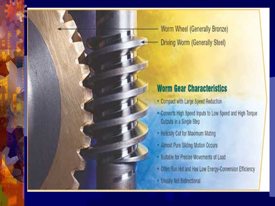
Worm Gears Worm Gears are used when extreme strength and precision are required, they are a combination of a hypoid gear and a spur gear. They provide very high gear reductions normally over 20 : 1 and even 40 : 1 Unless the worm rotates the gear cannot turn, thus locking the load in position regardless of weight. Many Worm Gears are used as Boat Winches due to their reliability and strength.

28
Examples of Worm Gears

30
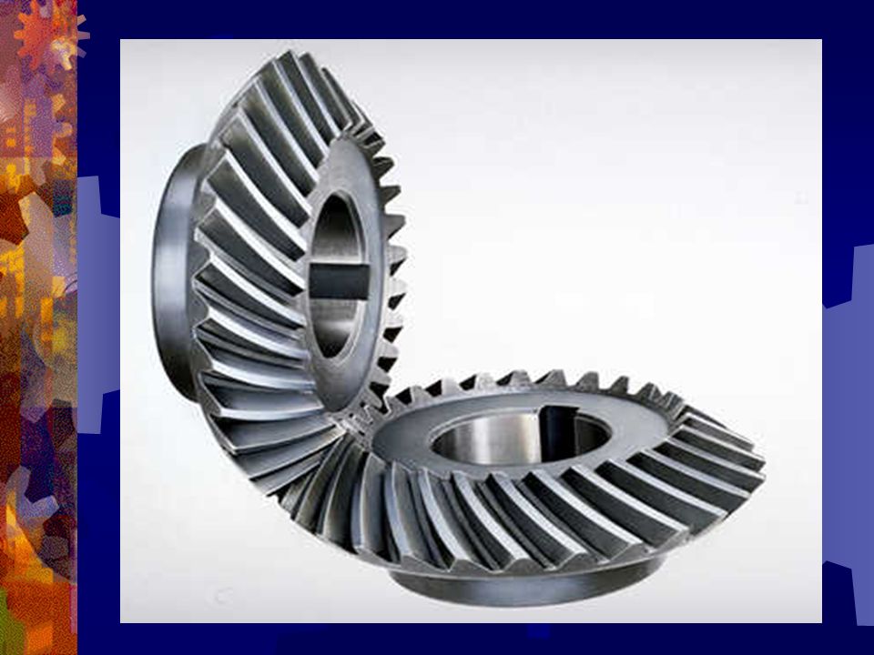
Bevel Gears Normally referred to as Right Angled Bevel Gears, they are commonly used to change the direction of rotation by 90°. They most commonly use spur gears, however their faces are cut at a 45° angle to each other to ensure a perfect mesh of the gear teeth. It is possible to say that a Hypoid Gear is a Bevel Gear just with a different tooth pattern.

31
Examples of Bevel Gears

33
Gear Backlash Also known as gear clearance.
Every gear assembly requires a very specific clearance between the gear teeth. If there is insufficient clearance between the teeth, the gears will heat up and fuse together due to the excess heat.

34
Gear Backlash If there is too much clearance between the gear teeth, the gear will crack and separate under load. The ideal backlash for most gears is no less than in. to no more than in. clearance

35
Gear Tooth Wear Patterns
Examples of tooth contact patterns when there is too little gear backlash.

36
Gear Tooth Wear Patterns
The ideal for gear backlash is to have the pattern more towards the center of the flank.

37
Conclusion While gears enable us to either increase speed or increase torque they are a very precise mechanism that requires careful attention to detail to ensure a long, reliable and durable lifespan. Set them up right and they’ll work for life! Set them up wrong and they won’t live for long!!

Similar presentations


 Two.>")


