Download presentation
Presentation is loading. Please wait.

1
Proposed LHC beam dumping kicker generator modifications for LS2 TE-TM Meeting Viliam Senaj 07/07/2015

2
LHC beam dump system

3
Beam dumping system of LHC LBDS – ultimate protection of LHC Number of generators per beam: – 15 extraction generators (MKD); 29 kV/19 kA – 4 horizontal dilution generators (MKBH); 27 kV/24 kA – 6 vertical dilution generators (MKBV); 16 kV/24 kA 2 parallel GTO stacks /MKD; 1 GTO stack per MKBH/MKBV Total of 800 GTO’s Dump at 7 TeV = total of 1 MA of kicker magnets current for both beams
; 29 kV/19 kA – 4 horizontal dilution generators (MKBH); 27 kV/24 kA – 6 vertical dilution generators (MKBV); 16 kV/24 kA 2 parallel GTO stacks /MKD; 1 GTO stack per MKBH/MKBV Total of 800 GTO’s Dump at 7 TeV = total of 1 MA of kicker magnets current for both beams")
4
MKD generator self-triggering GTO self-triggering observed with an HF burst few us prior to erratic Opposite phases in two snubber branches indicates resonant ringing between 2 parallel GTO stacks MKD erratic triggering = asynchronous dump = risk of damage of downstream instruments/quench SC quadrupole Similar signals (lower amplitude) observed on all generators in operation with an HF burst amplitude and repetition period dependent on generator voltage (E > 5 TeV)
 observed on all generators in operation with an HF burst amplitude and repetition period dependent on generator voltage (E > 5 TeV)")
5
Sparking in the GTO stack (before LS1) 30 s exposure in a dark room while charging to 29 kV – sparking visible and audible E-field simulation predicted E-value up to 8 MV/m; air ionization and charging of a return rod plexiglas insulator surface by sparking Sparking initiated resonant ringing between 2 parallel GTO stack at 2 MHz with a low damping factor
 30 s exposure in a dark room while charging to 29 kV – sparking visible and audible E-field simulation predicted E-value up to 8 MV/m; air ionization and charging of a return rod plexiglas insulator surface by sparking Sparking initiated resonant ringing between 2 parallel GTO stack at 2 MHz with a low damping factor")
6
Erratic type I 1 GTO stack starts to conduct first Magnet current rise time longer than normal: T_rise > 3 µs (vs. normal ~ 2.6 µs) Principal kind of erratic Tendency to get worse: lowering the energy of appearance Sometimes damage of 1 or more GTO’s due to not correct triggering Replacement of the stack for cleaning/replacement of damaged GTO
 Principal kind of erratic Tendency to get worse: lowering the energy of appearance Sometimes damage of 1 or more GTO’s due to not correct triggering Replacement of the stack for cleaning/replacement of damaged GTO.")
7
Erratic type II Sum of 2 GTO stack currents is lower than magnet current: part of current in alternative path (spark metal - metal?); peak magnet current ~0.6% higher than normal Magnet current rise time shorter than normal: T_rise < 2.5 µs (vs. normal ~ 2.6 µs) Observed only 4x till now; recently 1x in laboratory. No damage to GTO observed yet Regenerative phenomenon never 2x on the same generator (dirt burned by high current?) Visual inspection after erratic - 4x nothing found; recent erratic in lab – inspection with endoscope revealed 2 mosquitos and 1 “burned deposit” (fly?, mosquito?)
 Observed only 4x till now; recently 1x in laboratory. No damage to GTO observed yet Regenerative phenomenon never 2x on the same generator (dirt burned by high current ) Visual inspection after erratic - 4x nothing found; recent erratic in lab – inspection with endoscope revealed 2 mosquitos and 1 burned deposit (fly , mosquito ).")
8
Solutions to avoid sparking for LS1 Two solutions to avoid air ionization were proposed (E < 3MV/m) and tested in laboratory – sparking frequency reduced by a factor 10^3; no erratic during test in laboratory up to 7.1 TeV DC. Solution easier to implement (manpower) chosen (picture on right).
 chosen (picture on right)..")
9
Efficiency of sparking suppression Left side screenshot – initial situation: several sparks per minute at 7 TeV. Repetitive self triggering resulted in decreasing of the energy at which self triggering appears - after ~ 10 self triggering the phenomemenon appeared even at 6 TeV. Self triggering observed in laboratory as well. Sometimes self triggering leads to damage of GTO Picture on right - the same generator with insulators added: after 60 hours at 7 TeV in laboratory 44 events of much lower amplitude observed and no spontaneous triggering.

10
Summary of sparking related modifications during LS1 Replacement of the top insulator in the stack by a modified one Adding of insulators between GTO deflectors and Plexiglas tube to the most critical positions (4 top GTO’s) Replacement of vetronite tubes on the top of stack by araldite ones; tube serves to reduce risk of direct sparking between HV contact and ground plate by increasing sparking pathway distance Adding resistors in parallel to GTO gate-cathode to increase trigger transformer secondary loading and reduce mutual coupling between GTO Modification of material and position of a HV insulator supporting weight of principal capacitors (suspected possible surface discharge)
 Replacement of vetronite tubes on the top of stack by araldite ones; tube serves to reduce risk of direct sparking between HV contact and ground plate by increasing sparking pathway distance Adding resistors in parallel to GTO gate-cathode to increase trigger transformer secondary loading and reduce mutual coupling between GTO Modification of material and position of a HV insulator supporting weight of principal capacitors (suspected possible surface discharge)")
11
HV tests after LS1 modifications Various tests after refurbishment – one of them “Sparking test” – 48h at 7TeV (DC) – while recording sparking activity on generator: several erratic triggerings observed: – B1: 2 generators: H(8), O(4) no damaged GTO; average spark rate < 1spark/gen/24h – B2: 6 generators: A(1-type2), B(3, 6 damaged GTO), D(25 no damage), G(1-type2), J(3, 2 damaged GTO), N(2x type 1 + 1x type 2); average sparking rate > 4 sparks/gen/24h Generally, the generators that undergo erratic triggering presented higher sparking activity Found correlation between dust presence/quantity inside generators and sparking activity Dust penetrates into generator via perforated side panels (for PTU cooling) and when deposited in “sensitive area” contributes to sparking. Effect of insects in sensitive area observed as well Dust content (analysis in 2014): Ca, Si, O, Al (concrete), Fe, Cr, Ni (stainless steel), Ag (silver plating); Cu (quadrupoles water cooled cables maintenance nearby) Cleaning of dust inside generators reduced significantly sparking activity and erratic rate Observed a case when spark inside one generator initiated erratics in its neighbour via retrigger link (non equal sensitivity of PTM to a signal on retrigger link)
: Ca, Si, O, Al (concrete), Fe, Cr, Ni (stainless steel), Ag (silver plating); Cu (quadrupoles water cooled cables maintenance nearby) Cleaning of dust inside generators reduced significantly sparking activity and erratic rate Observed a case when spark inside one generator initiated erratics in its neighbour via retrigger link (non equal sensitivity of PTM to a signal on retrigger link).")
12
Endoscopic inspection of generator after erratic type 2 3 huge sparks observed during sparking test in laboratory at 7.1 TeV (within < 20h) – one of them finishing in type 2 erratic Found 2 mosquitos and 1 “burned deposit”; after removal of insects and “deposit”– 2 weeks of sparking test at 7.1 TeV without a single spark
 – one of them finishing in type 2 erratic Found 2 mosquitos and 1 burned deposit ; after removal of insects and deposit – 2 weeks of sparking test at 7.1 TeV without a single spark")
13
Main directions for long term solution In order to reduce probability of air ionisation and charge deposit – decision to make necessary modifications to GTO stack to reduce maximum E-field inside generator down to 1.5 MV/m (50% of the air ionisation limit ) Modification of mechanical support for main capacitors weight: no insulator any longer in contact with HV part Adding a CT into GTO snubber circuit for surveillance of the sparking activity within stack (to anticipate need of cleaning) Up-grade of the trigger transformer: reduced stray inductances (higher triggering current and its commutation speed) and independent secondary magnetic circuits (lower coupling between GTO) Installing of non-perforated side panels on the top part of generator (main capacitor compartment) Adding a damping ferrite on the top of GTO stack for damping of resonant ringing between parallel GTO stacks and reduction of T_rise
 Modification of mechanical support for main capacitors weight: no insulator any longer in contact with HV part Adding a CT into GTO snubber circuit for surveillance of the sparking activity within stack (to anticipate need of cleaning) Up-grade of the trigger transformer: reduced stray inductances (higher triggering current and its commutation speed) and independent secondary magnetic circuits (lower coupling between GTO) Installing of non-perforated side panels on the top part of generator (main capacitor compartment) Adding a damping ferrite on the top of GTO stack for damping of resonant ringing between parallel GTO stacks and reduction of T_rise")
14
Modifications of GTO stack

15
Effect of return rod displacement RR displacement [mm]0 Present situation 5101520 Inductance stack [nH]132141149157165 Inductance MKD total [µH]2.6822.6912.6992.7072.715 Voltage @ 7 TeV [kV]2929.0629.129.1429.19 Emax [MV/m]2.92.531.911.591.4 T_rise increase [ns]0+4+ 8+12+ 15
![Effect of return rod displacement RR displacement [mm]0 Present situation Inductance stack [nH] Inductance MKD total [µH] TeV [kV] Emax [MV/m] T_rise increase [ns]](http://images.slideplayer.com/24/6977064/slides/slide_15.jpg "Effect of return rod displacement RR displacement [mm]0 Present situation Inductance stack [nH] Inductance MKD total [µH] TeV [kV] Emax [MV/m] T_rise increase [ns]")
16
Solution with return rods displaced by 20 mm Return rods displaced by 20 mm and insulated by araldite; increased top flange hole HV contact insulated by araldite; top insulator modified – upper tube integral part Modified 4 upper HV deflectors - reduced diameter and fully insulated by araldite Modified 4 top snubber capacitors and HV dividers

17
Trigger transformer with reduced stray inductances Main goal – achieving triggering conditions recommended by producer Pin compatibility with present one Due to reduced stray inductance 2x higher I max and 3x higher dI/dt Reduction of T_rise by up to 150 ns Increase of the I_ref100% by up to 1 % (less switching losses) Secondary's with independent magnetic circuits - less coupling between GTOs and hence lower probability of erratic propagation within stack
 Secondary s with independent magnetic circuits - less coupling between GTOs and hence lower probability of erratic propagation within stack")
18
Further modifications tested but not implemented yet Adding a ferrite on the top of stack with a goal to increase a damping at the resonant frequency between 2 stacks. Its efficiency confirmed and at the same time reduction of T_rise by ~ 40 ns observed (magnetic compression effect); low cost, easy to implement Replacement of side perforated panels (principal capacitor compartment) by non-perforated ones to avoid dust penetration. Measurements in laboratory confirmed increase of internal temperature by 3.5 deg (discharge relay coil heating). Effect to the magnet current is hardly visible ~ - 0.05%; moderate cost, easy to implement Influence of the air flow direction to the erratic observed in laboratory: on a particular generators suffering from erratics, their presence/absence were dependent on the internal ventilator direction. Its modification or complete abandonment of forced cooling is expected to reduce risk of erratic at the expense of thermal stability of GTO compartment (heat generation on HV dividers). Due to influence of temperature to GTO behaviour the consequence would be reduced magnet current reproducibility (~+-0.5 %); to be fully evaluated; moderate cost – basically manpower only
; low cost, easy to implement Replacement of side perforated panels (principal capacitor compartment) by non-perforated ones to avoid dust penetration. Measurements in laboratory confirmed increase of internal temperature by 3.5 deg (discharge relay coil heating). Effect to the magnet current is hardly visible ~ %; moderate cost, easy to implement Influence of the air flow direction to the erratic observed in laboratory: on a particular generators suffering from erratics, their presence/absence were dependent on the internal ventilator direction. Its modification or complete abandonment of forced cooling is expected to reduce risk of erratic at the expense of thermal stability of GTO compartment (heat generation on HV dividers). Due to influence of temperature to GTO behaviour the consequence would be reduced magnet current reproducibility (~+-0.5 %); to be fully evaluated; moderate cost – basically manpower only.")
19
Validation tests Laboratory tests (as soon as possible): – HV DC test of individual stacks with photography of eventual sparking up to 40 kV – HV test of 2 prototype generators in laboratory up to 31 kV (equivalent of 7.6 TeV) during > 3 months; one generator with new trigger transformer Tunnel tests (if ~ 2 months reliability run available): few (2 + 2?) generators of 1 st series installed during EYETS
: – HV DC test of individual stacks with photography of eventual sparking up to 40 kV – HV test of 2 prototype generators in laboratory up to 31 kV (equivalent of 7.6 TeV) during > 3 months; one generator with new trigger transformer Tunnel tests (if ~ 2 months reliability run available): few (2 + 2 ) generators of 1 st series installed during EYETS")
20
Conclusion LS1 modifications were tested on prototypes in laboratory up to 29 kV (7.1 TeV) and even up to 31 kV (equiv. of 7.6 TeV) with total of ~ 10 generator x week – limited statistics Series application of modifications was found less effective – especially for generators installed in B2 (few months later than B1) Solutions adopted had most likely not sufficient margin for assembly errors/property defaults/dust deposit… Modified generators were not tested in laboratory due to tight planning Latest modifications offer more margin Dust penetration can be reduced and sensitive regions will be avoided (no removable tube on the top insulator) Endoscopic inspection will be included into procedure – less risk to miss any impurity
 with total of ~ 10 generator x week – limited statistics Series application of modifications was found less effective – especially for generators installed in B2 (few months later than B1) Solutions adopted had most likely not sufficient margin for assembly errors/property defaults/dust deposit… Modified generators were not tested in laboratory due to tight planning Latest modifications offer more margin Dust penetration can be reduced and sensitive regions will be avoided (no removable tube on the top insulator) Endoscopic inspection will be included into procedure – less risk to miss any impurity.")
22
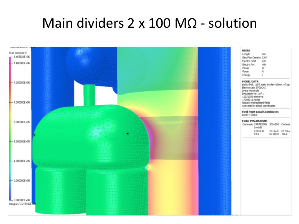
Main dividers 2 x 100 MΩ - solution

24
HV divider 10 x 5 MΩ – solution

25
HV contact region - today

26
HV contact region - solution

Similar presentations


 MPP meeting 8/5/2015.>")


 CLIQ system overview 2) Adding lead to pizza box 3) remote triggering.>")
