Download presentation
Presentation is loading. Please wait.

1
COULOMB ’05 Experiments with Cooled Beams at COSY A.Lehrach, H.J.Stein, J. Dietrich, H.Stockhorst, R.Maier, D.Prasuhn, V.Kamerdjiev, COSY, Juelich, I.Meshkov, Yu.Korotaev, A.Sidorin, A.Smirnov, JINR, Dubna

2
Contents 1. Introduction: Electron cooling at COSY 2.“Electron heating” 3. Coherent instability 4. Ion cloud in an electron cooling system

3
COSY Accelerator Facility Ions: (pol. & unpol.) p and d Momentum:300/600 to 3700 MeV/c for p/d, respectively Circumference of the ring: 184 m Injection: 45 MeV H-, D- stripping injection Intensity 8 mA: 10 11 protons coasting beam Electron Cooling at injection Stochastic Cooling above 1.5 GeV/c 4 internal and 3 external experimental areas
 p and d Momentum:300/600 to 3700 MeV/c for p/d, respectively Circumference of the ring: 184 m Injection: 45 MeV H-, D- stripping injection Intensity 8 mA: protons coasting beam Electron Cooling at injection Stochastic Cooling above 1.5 GeV/c 4 internal and 3 external experimental areas.")
4
COSY Electron Cooling system Design values Cooling section length2 m Electron current 4 A Beam diameter 2.54 cm Energy 100 keV Normal operation Energy 25 keV Current 100 – 250 mA Magnetic field 800 G Applications 1.On-turn extraction using diagnostics kicker (JESSICA) 2.Increase of the beam quality for slow extraction (TOF) 3.Increase of polarized beam intensity (cooling-stacking)
 2.Increase of the beam quality for slow extraction (TOF) 3.Increase of polarized beam intensity (cooling-stacking)")
5
Beam shrinks and decays Typical graphs at injection in COSY The dependence on time (a) neutrals generation rate and (b) proton beam intensity (1.275·10 10 protons/div). Initial losses “Coherent”losses

6
2. «Electron heating» «Measurements of electron cooling and «electron heating» at CELSIUS» D.Reistad et al. Workshop on Beam Cooling, Montreux, 1993 In presence of the electron beam the ion beam lifetime is much shorter: 50 - 100 sec without electron beam 0.5 - 1 sec at electron current of 100 mA

7
COSY, detuned electron beam I e = 0 I e = 45 mA I e = 98 mA I e = 243 m A

8
r I -0.5 N Q = const Equilibrium beam emittance At small intensity equilibrium between electron cooling and IBS leads to N 0.6 H 0 profiles At large intensity Heating by high order resonances

9
Nonlinear field of the electron beam CELSIUS: Ion beam cross-section 70 x 58 mm electron beam diameter 20 mm COSY: Ion beam cross-section 40 x 75 mm electron beam diameter 25.4 mm Two-beam instability V.Parkhomchuk, D.Pestrikov, Coherent instabilities at electron cooling, Workshop on Beam Cooling, Montreux, 1993

10
3.Coherent instability at COSY Single injection in COSY I p (t) H 0 (t) Initial losses Coherent oscillation start (no losses!) Oscillations “jump” (see next slide)
 H 0 (t) Initial losses Coherent oscillation start (no losses!) Oscillations jump (see next slide)")
11
Coherent instability development 1 injection (t = 0), 2 horizontal betatron oscillations start (t=8 s), 3 “jump” to vertical oscillations (t = 16 s), t jump < 0.5 s 1 (t = 0) 2 (t=8 s) 3 (t = 16 s) Q x = 3.62 Q y =3.66
, 2 horizontal betatron oscillations start (t=8 s), 3 jump to vertical oscillations (t = 16 s), t jump < 0.5 s 1 (t = 0) 2 (t=8 s) 3 (t = 16 s) Q x = 3.62 Q y =3.66")
12
H. Stockhorst 5.Coherent instability COSY: Sextupole correction “Standard” setting of sextupoles Optimised setting of sextupoles As result of correction accelerated beam increased in two times

13
Qx=3.609, Qy=3.694 x=− 2.8, y=0.3 Qx=3.598, Qy=3.636 x=− 2.4, y=− 0.6 Schottky Spectrum

14
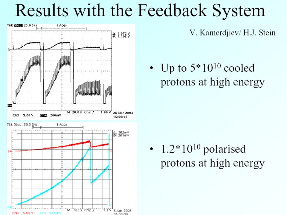
Instability suppression Feedback system: LEAR: (CERN) bandwidth 500 MHz - 8 10 10 protons COSY: bandwidth 70 MHz - 10 11 stored protons Variation of electron beam energy, CELSIUS: Most effective square-wave modulation 50 V amplitude at 115 keV electron beam energy “Hollow beam”, Measuring a hollow electron beam profile, A. V. Bubley, V. M. Panasyuk, V. V. Parkhomchuk and V. B. Reva, NIM A 532 (October 2004)
.")
16
P. Zenkevich, A. Dolinskii and I. Hofmann Dipole instability of a circulating beam due to the ion cloud in an electron cooling system, NIM A 532 (October 2004) E.Syresin, K.Noda, T.Uesugi, I.Meshkov, S.Shibuya, Ion lifetime at cooling stacking injection in HIMAC, HIMAC-087, May 2004 4. Ion cloud in an electron cooling system
 E.Syresin, K.Noda, T.Uesugi, I.Meshkov, S.Shibuya, Ion lifetime at cooling stacking injection in HIMAC, HIMAC-087, May Ion cloud in an electron cooling system.")
17
“Natural” neutralization Potential at the electron beam axis Neutralization level due to variation of the vacuum chamber radius Neutralization measurements Vacuum chamber radius At gun and collector 3.25 cm At cooling section 7.5 cm Natural neutralization 34-37% Potential depression by space charge 45V/100mA (theo.) 30V/100mA (meas.)
 30V/100mA (meas.)")
18
Control of the neutralization level “Shaker” – resonant excitation of the ion oscillations Trapped residual gas ions oscillate in the solenoid magnetic field and electric field of the electron beam: Change of neutralization leads to the shift in proton revolution frequency I e = 250 mA 18 harmonics

19
A/Z of residual gas ions stored in electron beam Transverse shaking Longitudinal shaking 16 40 28 Ions traveling along cooler I e = 170 mA Revolution frequency shift is compensated by change of cathode voltage CO + N2+N2+ Xe + H+H+ Constant beam revolution frequency

20
Non resonance excitation Shaker is off Resonance 100-120 kHzResonance 130-150 kHz

21
Conclusion 1.Electron cooling permits to form ion beams at high phase space density, however the problems of beam stability specific for electron cooler rings appear. 2. First problem relates to interaction of an ion circulating in the ring with nonlinear field of cooling electron beam. 3. Second problem is connected with development of coherent instability in cooled ion beam. 4. The threshold of this instability can be reduced when “secondary” ions of residual gas are being stored in the cooling electron beam. 5. The threshold of this instability can be increased when feedback system and control of “the natural neutralization” (with a shaker, for instance) are applied.
 are applied..")
Similar presentations

 and L. F. Wang (SLAC) ECLOUD07, 12th Apr. 2007, Daegu, Korea 1. Introduction 2. Ion trapping 3. Fast ion instability.>")


>")


 at IUCF V.S. Morozov MEIC Collaboration Meeting March 30-31, 2015.>")


