Download presentation
Presentation is loading. Please wait.

1
Vector Control of Induction Machines

2
Introduction The traditional way to control the speed of induction motors is the V/Hz-control Low dynamic performance In applications like servo drives and rolling mills quick torque response is required. Desire to replace dc drives led to vector control Braunschweig, Leonhard, Blaschke, Hasse, late 70-ies

3
What is vector control? Vector control implies that an ac motor is forced to behave dynamically as a dc motor by the use of feedback control. Always consider the stator frequency to be a variable quantity. Think in synchronous coordinates.

4
Basic blocks of a vector controlled drive

5
Addition of a block for calculation of the transformation angle

6
The current is controlled in the d- and q-directions
magnetization torque production

7
Vector controller

8
Stator and rotor of an induction machine

9
Magnetization current from the stator

10
The flux

11
The rotation

12
View from the rotor

13
Induced voltage and current

14
Torque production

15
Ampere-turn balance

16
Rotor flux orientation
Difficult to find the transformation angle since the direction of the flux must be known Flux measurement is required Flux sensors (and fitting) are expensive and unreliable Rotor position measurement does not tell the flux position The solution is flux estimation
 are expensive and unreliable. Rotor position measurement does not tell the flux position. The solution is flux estimation.")
17
Rotor flux orientation using measured flux
Original method suggested by Blaschke Requires flux sensors Flux coordinates: aligned with the rotor flux linkage

18
Rotor flux orientation

19
From Chapter 4

20
Transformation to flux coordinates

21
The flux coordinate system is ”synchronous” only at steady-state
The flux coordinate system is ”synchronous” only at steady-state. During transients the speed of the rotor flux and the stator voltage may differ considerably.

22
The rotor equation (5.9)
")
23
Split into real and imaginary parts

24
Rotor flux dynamics are slow

25
Torque control

26
Rotor flux orientation using estimated flux
The rotor flux vector cannot be measured, only the airgap flux. Flux sensors reduce the reliability Flux sensors increase the cost Therefore, it is better to estimate the rotor flux.

27
The "current model" in the stator reference frame (Direct Field Orientation)
")
28
The current model

29
The "current model" in synchronous coordinates (Indirect Field Orientation)
")
30
Transformation angle

31
Remarks on indirect field orientation
Does not directly involve flux estimation (superscript f dropped) Not ”flux coordinates” but ”synchronous coordinates” Since the slip relation is used instead of flux estimation, the method is called indirect field orientation
 Not flux coordinates but synchronous coordinates Since the slip relation is used instead of flux estimation, the method is called indirect field orientation.")
32
Indirect field orientation based on the current model

33
Feedforward rotor flux orientation
Significantly reduced noise in the transformation angle Fast current control is assumed (ref.value=measured value) No state feedback => completely linear
 No state feedback => completely linear.")
34
The voltage model The current model needs accurate values of the rotor time constant and rotor speed The trend is to remove sensors for cost and reliability reasons Simulate the stator voltage equation instead of the rotor voltage equation

35
Solve for the rotor current and insert in

36
Multiplication by yields Solve for

37
Direct field orientation using the voltage model

38
Stator flux orientation
"Direct self-control" (DSC) schemes first suggested by Depenbrock, Takahashi, and Noguchi in the 1980s. At low frequencies the current model can be used together with:
 schemes first suggested by Depenbrock, Takahashi, and Noguchi in the 1980s. At low frequencies the current model can be used together with:")
39
Field weakening

40
Current control

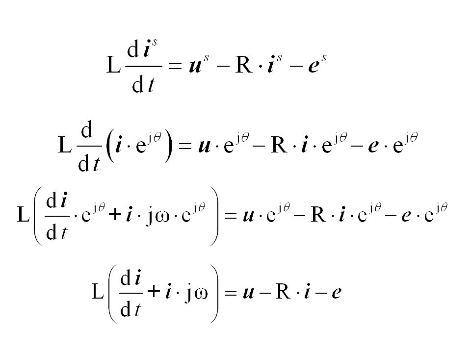
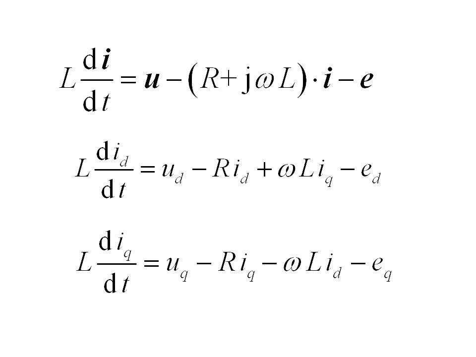
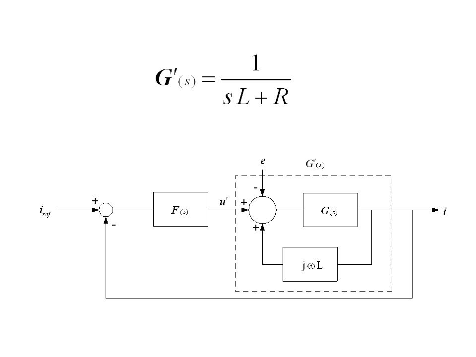
43
Transfer function and block diagram of a three-phase load

44
Review of methods for current control
Hysteresis control Stator frame PI control Synchronous frame PI control

45
Hysteresis control (Tolerance band control)
Measure each line current and subtract from the reference. The result is fed to a comparator with hysteresis. Pulse width modulation is achieved directly by the current control The switching frequency is chosen by means of the width of the tolerance band. No tuning is required. Very quick response

46
Drawbacks of hysteresis control
The switching frequency is not constant. The actual tolerance band is twice the chosen one. Sometimes a series of fast switchings occur. Suitable for analog implementation. Digital implementation requires a very high sampling frequency.

47
Stator frame PI control
Two controllers: one for the real axis and one for the imaginary axis Cannot achieve zero steady-state error Tracking a sinusoid means that steady-state is never reached in a true sense Integral action is useless except at zero frequency

48
Synchronous frame PI control
In a synchronous reference frame the current is a dc quantity at steady-state. Zero steay state error is possible. Coordinate transformations necessary Easily implemented on a DSP Usually the best choice!

49
Design of synchronous frame PI controllers
Remove cross-coupling

51
Desired closed-loop system

52
Choice of controller parameters

53
Speed control Applications: pumps and fans in the process industry, paper and steel mills, robotics and packaging, electric vehicles Very different dynamic requirements Most drives have low to medium high requirements on dynamics. These drives are considered here. Cascade control is sufficient

54
Block diagram of a speed-controlled drive system

55
The mechanical system

56
The speed controller The task of the speed controller is to provide a reference value for the torque (or current) which makes the mechanical system respond to the speed reference with a specified rise time.
 which makes the mechanical system respond to the speed reference with a specified rise time.")
57
Block diagram with speed controller

59
Choice of controller parameters

60
Realistic choice of bandwidth
Care must be taken that the bandwidth of the speed controller is not unnecessarily high. In fact this should be decided during the first steps in the design process of a drive system The bandwidth is directly connected to the current rating of the inverter.

61
A change in the speed reference
How large steps should be foreseen?

62
Check if the current controller is sufficiently fast.
With and Check if the current controller is sufficiently fast.

Similar presentations


 f(x,u) u x f(x, (x) x. Example: Using feed-forward, what should be canceled?>")


