Download presentation
Presentation is loading. Please wait.

1
Using Rotatable and Directional (R&D) Sensors to Achieve Temporal Coverage of Objects and Its Surveillance Application You-Chiun Wang, Yung-Fu Chen, and Yu-Chee Tseng IEEE TRANSACTIONS ON MOBILE COMPUTING 2011
 Sensors to Achieve Temporal Coverage of Objects and Its Surveillance Application You-Chiun Wang, Yung-Fu Chen, and Yu-Chee Tseng IEEE TRANSACTIONS ON MOBILE COMPUTING 2011")
2
Outline Introduction R&D Sensor Surveillance System Goal Assumptions Overview Maximum Covering Deployment (MCD) Heuristic Disk-Overlapping Deployment (DOD) Heuristic Performance evaluation Conclusions
 Heuristic Disk-Overlapping Deployment (DOD) Heuristic Performance evaluation Conclusions")
3
Introduction Due to hardware design or cost consideration, sensors may possess sector-like sensing coverage. By stepper motors, sensors can rotate to cover the objects around them. This type of sensors are called rotatable and directional (R&D) sensors. infrared, camera, and ultrasonic sensors
 sensors. infrared, camera, and ultrasonic sensors.")
4
Introduction R&D sensors have many real-life applications: providing visual monitoring of the environment identifying the positions of objects temporal coverage model guarantee each object to be monitored by sensors for at least a threshold ratio of time per period.

5
R&D Sensor Surveillance System The event-driven surveillance system by R&D sensors.

6
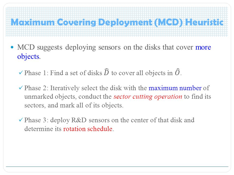
Goal R&D sensor deployment problem deploy the minimum number of sensors to cover a given set of objects to satisfy their temporal coverage requirements.

7
Assumptions SiSi okok rsrs SiSi rsrs a b Sector A Sector B SiSi ABABA frame 0.5T … the duration that a sensor stops to monitor the objects in one sector the duration that a sensor rotates from one sector to the next sector

8
Definition SiSi rsrs a b Sector A Sector B SiSi ABABA frame 0.5T … the duration that a sensor stops to monitor the objects in one sector the duration that a sensor rotates from one sector to the next sector

9
Overview Sector G Sector F Sector E Sector B Sector C Sector D Sector A SbSb SaSa object R&D sensor disk d a disk d b Maximum Covering Deployment (MCD) Heuristic Disk-Overlapping Deployment (DOD) Heuristic
 Heuristic Disk-Overlapping Deployment (DOD) Heuristic")
10
Maximum Covering Deployment (MCD) Heuristic
 Heuristic")
12
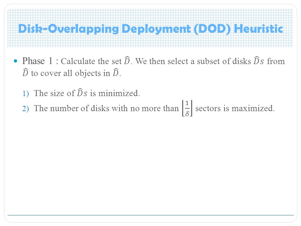
[50] B. Xiao, Q. Zhuge, Y. He, Z. Shao, and E.H.M. Sha, “Algorithms for disk covering problems with the most points,” Proc. IASTED Int’l Conf. Parallel and Distributed Computing and Systems, pp. 541– 546, 2003. 1)If two objects have a distance smaller than 2r s, we place two disks such that their circumferences intersect at these two objects. 2) If two objects have a distance equal to 2r s, we place a disk such that its circumference passes these two objects. 3) If an object is isolated, in the sense that its distance to the nearest object is larger than 2r s, we place a disk such that its center locates at the object.
![[50] B. Xiao, Q. Zhuge, Y. He, Z. Shao, and E.H.M.](http://images.slideplayer.com/24/6950763/slides/slide_12.jpg "Sha, Algorithms for disk covering problems with the most points, Proc. IASTED Int’l Conf. Parallel and Distributed Computing and Systems, pp. 541– 546, )If two objects have a distance smaller than 2r s, we place two disks such that their circumferences intersect at these two objects. 2) If two objects have a distance equal to 2r s, we place a disk such that its circumference passes these two objects. 3) If an object is isolated, in the sense that its distance to the nearest object is larger than 2r s, we place a disk such that its center locates at the object..")
13
Maximum Covering Deployment (MCD) Heuristic Phase 2: conduct the sector cutting operation to find its sectors, and mark all of its objects. 1) Indexing and clustering 2) Deciding sectors SaSa o1o1 Cluster 1 o2o2 o3o3 o4o4 o5o5 o6o6 o7o7 o8o8 o9o9 Cluster 2 Cluster 3 Sector A Sector C Sector B SaSa o1o1 Cluster 1 o2o2 o3o3 o4o4 o5o5 o6o6 o7o7 o8o8 o9o9 Cluster 3 Cluster 2 Cluster 3
 Indexing and clustering 2) Deciding sectors SaSa o1o1 Cluster 1 o2o2 o3o3 o4o4 o5o5 o6o6 o7o7 o8o8 o9o9 Cluster 2 Cluster 3 Sector A Sector C Sector B SaSa o1o1 Cluster 1 o2o2 o3o3 o4o4 o5o5 o6o6 o7o7 o8o8 o9o9 Cluster 3 Cluster 2 Cluster 3.")
14
Maximum Covering Deployment (MCD) Heuristic Phase 2: 1) Indexing and clustering SaSa Start from this object o1o1 Cluster 1
 Heuristic Phase 2: 1) Indexing and clustering SaSa Start from this object o1o1 Cluster 1")
15
Maximum Covering Deployment (MCD) Heuristic Phase 2: 1) Indexing and clustering SaSa o1o1 Cluster 1 o2o2
 Heuristic Phase 2: 1) Indexing and clustering SaSa o1o1 Cluster 1 o2o2")
16
Maximum Covering Deployment (MCD) Heuristic Phase 2: 1) Indexing and clustering SaSa o1o1 Cluster 1 o2o2 o3o3 o4o4 o5o5 o6o6 o7o7 o8o8 o9o9 Cluster 2 Cluster 3
 Heuristic Phase 2: 1) Indexing and clustering SaSa o1o1 Cluster 1 o2o2 o3o3 o4o4 o5o5 o6o6 o7o7 o8o8 o9o9 Cluster 2 Cluster 3")
17
Sector C Sector A Sector B Maximum Covering Deployment (MCD) Heuristic Phase 2: 2) Deciding sectors Cluster sequence : K; 1; 2; ・ ・ ・ ;K − 1. each cluster starting from the uncovered object with smallest index SaSa o1o1 Cluster 1 o2o2 o3o3 o4o4 o5o5 o6o6 o7o7 o8o8 o9o9 Cluster 2 Cluster 3 SaSa o1o1 Cluster 1 o2o2 o3o3 o4o4 o5o5 o6o6 o7o7 o8o8 o9o9 Cluster 3 Cluster 2 Cluster 3

18
Maximum Covering Deployment (MCD) Heuristic Phase 3: deploy R&D sensors on the center of that disk and determine its rotation schedule. SiSi rsrs a b Sector A Sector B SjSj rsrs e Sector E Sector C f Sector F Sector D c d disk d i disk d j

19
Maximum Covering Deployment (MCD) Heuristic Phase 3: deploy R&D sensors on the center of that disk and determine its rotation schedule. SiSi rsrs a b Sector A Sector B SjSj rsrs e Sector E Sector C f Sector F Sector D c d disk d i disk d j

20
Maximum Covering Deployment (MCD) Heuristic When objects are arbitrarily placed in the sensing field, each sector may cover only few objects. In this case, each disk requires more sectors to cover its objects and thus we may need to deploy multiple sensors on each of most disks.

21
Disk-Overlapping Deployment (DOD) Heuristic
 Heuristic")
24
object unmarked

25
Disk-Overlapping Deployment (DOD) Heuristic
 Heuristic")
27
Sector G Sector F Sector E Sector B Sector C Sector D Sector A SbSb SaSa disk d a disk d b

28
Disk-Overlapping Deployment (DOD) Heuristic Sector G Sector F Sector E Sector B Sector C Sector D Sector A SbSb SaSa disk d a disk d b joint sectors : Sector A, Sector B, Sector E Non-joint sectors : Sector C, Sector D, Sector F, Sector G
 Heuristic Sector G Sector F Sector E Sector B Sector C Sector D Sector A SbSb SaSa disk d a disk d b joint sectors : Sector A, Sector B, Sector E Non-joint sectors : Sector C, Sector D, Sector F, Sector G")
29
Disk-Overlapping Deployment (DOD) Heuristic SiSi disk d i
 Heuristic SiSi disk d i")
30
Disk-Overlapping Deployment (DOD) Heuristic Sector G Sector F Sector E Sector B Sector C Sector D Sector A SbSb SaSa disk d a disk d b joint sectors : Sector A, Sector B, Sector E Non-joint sectors : Sector C, Sector D, Sector F, Sector G
 Heuristic Sector G Sector F Sector E Sector B Sector C Sector D Sector A SbSb SaSa disk d a disk d b joint sectors : Sector A, Sector B, Sector E Non-joint sectors : Sector C, Sector D, Sector F, Sector G")
31
Disk-Overlapping Deployment (DOD) Heuristic SiSi Sector G Sector F Sector E Sector B Sector C Sector D Sector A SbSb SaSa disk d a disk d b Sector cutting operation
 Heuristic SiSi Sector G Sector F Sector E Sector B Sector C Sector D Sector A SbSb SaSa disk d a disk d b Sector cutting operation")
32
Maintaining the network connectivity our deployment heuristics focus on covering all objects, but the network may not be connected. we add extra relay nodes to maintain the network connectivity. [44] X. Han, X. Cao, E.L. Lloyd, and C.C. Shen, “Deploying directional sensor networks with guaranteed connectivity and coverage,” Proc. IEEE Conf. Sensor, Mesh and Ad Hoc Comm. and Networks, pp. 153–160, 2008.

33
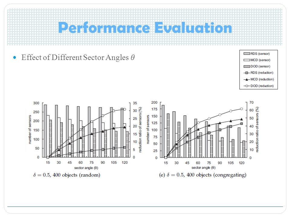
Performance Evaluation

34
Effect of Different Object Numbers random distribution of objects congregating distribution of objects

35
Performance Evaluation

37
0.40.30.20.1 23510 Most number of sensors6432

38
Conclusions In this paper, we have defined a temporal coverage model to monitor objects. Two efficient heuristics are proposed : MCD deploys sensors to cover the disks with more objects. DOD deploys sensors to cover joint sectors to exploit disk overlap.

Similar presentations


 Ming Ma, Yuanyuan Yang IEEE Transactions.>")


 Department of Computer Science,>")


