Download presentation
Presentation is loading. Please wait.

1
Space Power Facility (SPF) CEV Environmental Qualification Testing DISCLAIMER: This Initial Government Concept does not represent a preferred Government approach or solution.
 CEV Environmental Qualification Testing DISCLAIMER: This Initial Government Concept does not represent a preferred Government approach or solution.")
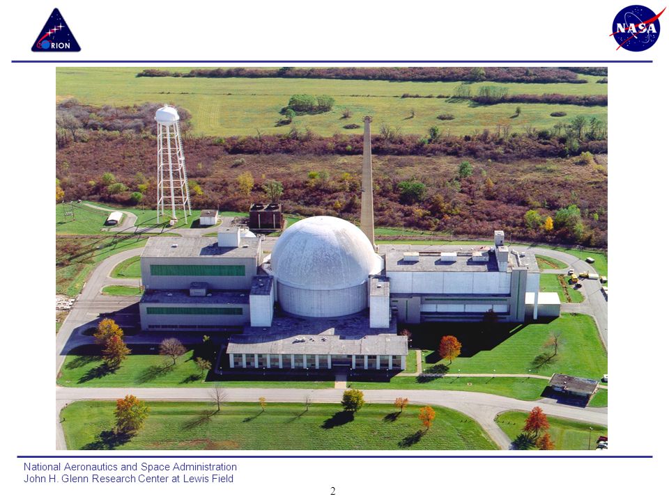
3
Space Power Facility Cutaway View

4
Facility Architecture for CEV Testing
Random and Acoustic Vibration Test Area Thermal/Vacuum and EMI/EMC Test Area Assembly and Integration Area

5
Operations Flow * SPF Specific Schemes/Techniques Provide Low Risk Handling of Hardware

6
Major Area for Facility Upgrades Vibration Test Area

7
EMI/EMC Testing All tests are performed inside the aluminum vacuum chamber using the chamber as an RF shield Minimum facility modifications required Facility survey was performed showing very low RF noise Utilizes large chamber size to position EMI equipment using movable platforms

8
EMI/EMC Testing Aluminum vacuum chamber is well suited for radiated susceptibility testing, and for radiated emissions testing Data traces shown in figure indicate that the RF energy penetrating into the chamber is below thresholds used in the International Space Station Program

9
Random Vibration Testing
Large 3 axis state-of-the-art shaker system sized to test CEV full stack and LSAM (LSAM mass 120,000 lbs) 7 shaker system allows for ease of changeover to vertical axis testing 4 – 45,000 lb horizontal 3 – 65,000 lb vertical New data acquisition and control system 450 channel data acquisition system will be used for both random and acoustic vibration testing 1.4 million lb seismic mass installed in high bay Shaker slip table below grade allows for full stack testing Facility can be modified to handle tanks filled with isopropyl alcohol
 7 shaker system allows for ease of changeover to vertical axis testing. 4 – 45,000 lb horizontal. 3 – 65,000 lb vertical. New data acquisition and control system. 450 channel data acquisition system will be used for both random and acoustic vibration testing. 1.4 million lb seismic mass installed in high bay. Shaker slip table below grade allows for full stack testing. Facility can be modified to handle tanks filled with isopropyl alcohol.")
10
Acoustic Vibration Testing Chamber Characteristics
Build a new 80,000 ft3 (40ft x 45ft x 46 ft tall) RATF with capability of 163 dB in the empty chamber The design of this chamber utilizes known state-of-the-art technology for acoustic testing at these levels and is considered the most powerful chamber that can be built of this size Chamber size is large enough to test the integrated SA/SM/CM/LAS boost cover and the LAS tower as a separate test Chamber size and chamber access doors are large enough to allow testing of the LSAM GRC Utilized Wyle Laboratories for proposal information (worlds leading expert in building acoustic facilities) Typical 60,000 ft3 Reverberant Acoustic Test Facility
 RATF with capability of 163 dB in the empty chamber. The design of this chamber utilizes known state-of-the-art technology for acoustic testing at these levels and is considered the most powerful chamber that can be built of this size. Chamber size is large enough to test the integrated SA/SM/CM/LAS boost cover and the LAS tower as a separate test. Chamber size and chamber access doors are large enough to allow testing of the LSAM. GRC Utilized Wyle Laboratories for proposal information (worlds leading expert in building acoustic facilities) Typical 60,000 ft3 Reverberant Acoustic Test Facility.")
11
Thermal Vacuum Testing
Cryogenic Systems Reconfigure existing shroud panels to 40 foot tall x 40 wide x 80 ft long envelope Cryopanel end walls will swing open to allow test article insertion Assembly platform with attached cryofloor will be used for build-up of test article in Assembly Area and allow integrated unit to be moved to test chamber on rail system ISS Testing Cryoshroud Configuration Solar Simulation Build test specific lamp structure Full surround lamp structure with movable sections to allow deployments Existing Power Supply/Controllers 14 zones (7.2 MW) Maximum 400 kW/zone. SCR control Existing chamber penetrations utilized Orion Cryoshroud Concept with Doors Closed
 Maximum 400 kW/zone. SCR control. Existing chamber penetrations utilized. Orion Cryoshroud Concept with Doors Closed.")
12
Thermal Shroud System Designed for LSAM Testing
CEV Testing Deployable Structures LSAM Testing in Lunar Surface Configuration

13
Existing Cryogenic Systems
Capable of removing up to 14 MW of heat 28 K GAL LN2 STORAGE (60 PSI SUPPLY) 200 K LN2 TANK LOW PRESSURE STORAGE ELECTRIC LN2 VAPORIZER FOR GN2 GN2 STORAGE ~ 70, PSI CRYOSHROUD GN2 RECIRCULATION COOLED WITH LN2 DESUPERHEATER LN2 SUPPLY FOR CRYOSHROUD AND DIFFUSION PUMP BAFFLES AND TEST SPECIFIC HARDWARE 11,000 CFM COMPRESSORS CIRCULATE GN2 THRU CRYOSHROUD SPF LN2 & GN2 Distribution Systems
 200 K LN2 TANK LOW PRESSURE STORAGE. ELECTRIC LN2 VAPORIZER FOR GN2. GN2 STORAGE ~ 70, PSI. CRYOSHROUD GN2 RECIRCULATION COOLED WITH LN2 DESUPERHEATER. LN2 SUPPLY FOR CRYOSHROUD AND DIFFUSION PUMP BAFFLES AND TEST SPECIFIC HARDWARE. 11,000 CFM COMPRESSORS CIRCULATE GN2 THRU CRYOSHROUD. SPF LN2 & GN2 Distribution Systems.")
14
Infrared Lamp System INFRARED HEAT LAMP SYSTEM DESIGN CHARACTERISTICS
USES TUNGSTEN QUARTZ LAMPS AUTOMATIC HEAT FLUX CONTROL CLOSED LOOP TEMP CONTROL VARIABLE TEMPERATURE RANGE INDEPENDENT CONTROLLED BANKS 7 MW POWER AVAILABLE INSIDE CHAMBER

15
Ancillary Facility Support Systems
General Maintenance and certification is in progress for the following systems Chamber door and bridge systems 8000 GPM closed system cooling tower Gaseous nitrogen system Facility service air system psig Electrical substation - 14 MW available Emergency power generator Facility Lifting Devices

Similar presentations


>")
>")


, is among the world leaders in the field of designing and manufacturing of components and.>")


 ENVIRONMENTAL STRESSES SCREENING.>")


