Download presentation
Presentation is loading. Please wait.

1
9/12/20151

9
Most optical fibers are used for transmitting information over long distances. Two major advantages of fiber: (1) wide bandwidth and (2) low loss. Attenuation cause mainly by absorption and scattering. Bandwidth is limited by an effect called dispersion.
 wide bandwidth and (2) low loss. Attenuation cause mainly by absorption and scattering. Bandwidth is limited by an effect called dispersion..")
10
Attenuation mainly due to material absorption, material scattering. Others include bending losses, mode coupling losses and losses due to leaky modes There are also losses at connectors and splices Effect of Attenuation A receiver in an optical system requires a minimum optical input power to operate with a specific error probability. Attenuation reduces the optical power available, degrading the error probability. Most system specifications allow a maximum error probability of 1X10 -9 There are a number of major causes of attenuation in fiber

11
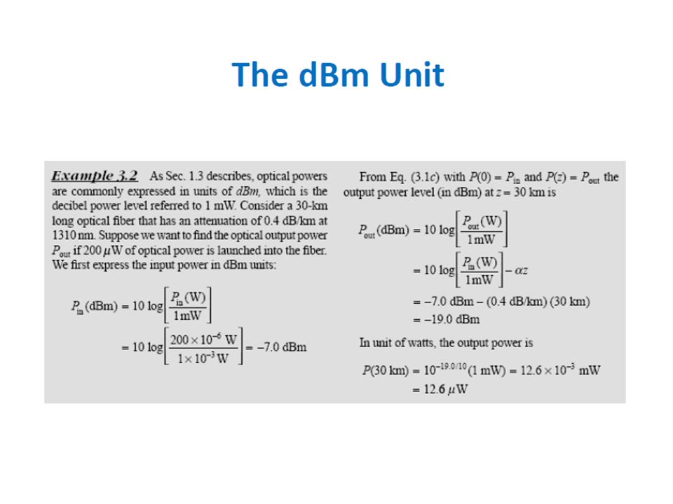
Logarithmic relationship between the optical output power and the optical input power Measure of the decay of signal strength or light power where: P(z) = Optical Power at distance z from the input P o = Input optical power (W) - ’ = Fiber attenuation coefficient, [dB/km] 9/12/201511
![ Logarithmic relationship between the optical output power and the optical input power Measure of the decay of signal strength or light power where: P(z) = Optical Power at distance z from the input P o = Input optical power (W) - ’ = Fiber attenuation coefficient, [dB/km] 9/12/201511](http://images.slideplayer.com/23/6873732/slides/slide_11.jpg " Logarithmic relationship between the optical output power and the optical input power Measure of the decay of signal strength or light power where: P(z) = Optical Power at distance z from the input P o = Input optical power (W) - ’ = Fiber attenuation coefficient, [dB/km] 9/12/201511")
12
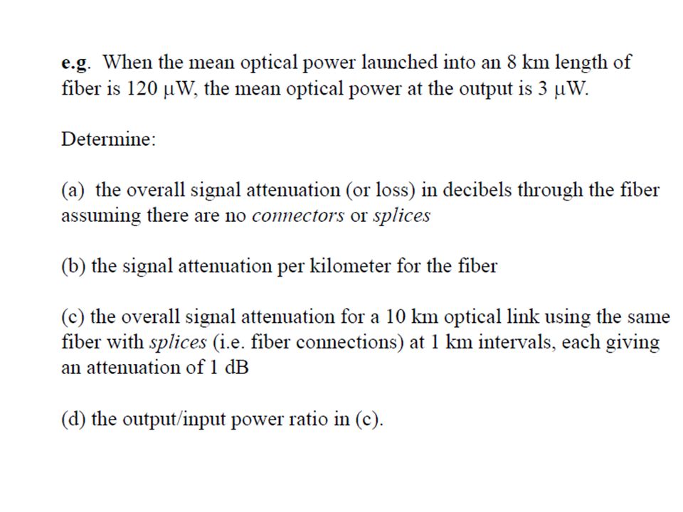
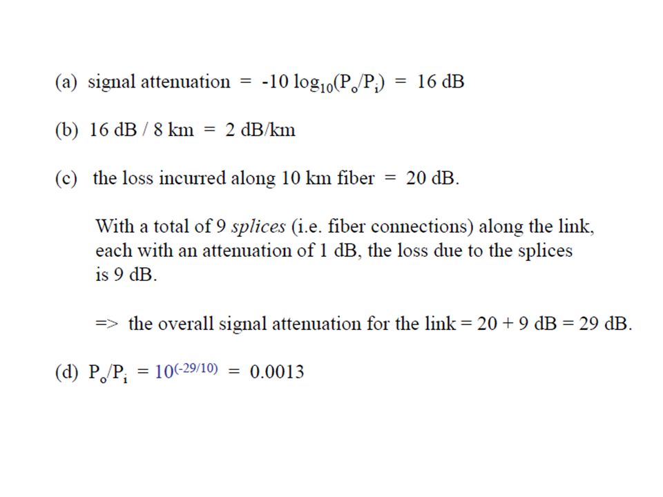
Usually, attenuation is expressed in terms of decibels Attenuation Conversion: = 4.343 ’ where: P(z) = Optical Power at distance z from the input P o = Input optical power = Fiber attenuation coefficient, [dB/km] = scattering + absorption + bending 9/12/201512
![ Usually, attenuation is expressed in terms of decibels Attenuation Conversion: = ’ where: P(z) = Optical Power at distance z from the input P o = Input optical power = Fiber attenuation coefficient, [dB/km] = scattering + absorption + bending 9/12/201512](http://images.slideplayer.com/23/6873732/slides/slide_12.jpg " Usually, attenuation is expressed in terms of decibels Attenuation Conversion: = ’ where: P(z) = Optical Power at distance z from the input P o = Input optical power = Fiber attenuation coefficient, [dB/km] = scattering + absorption + bending 9/12/201512")
13
Types of Attenuation 1- Material Absorption losses 2- Intrinsic Absorption 3- Extrinsic Absorption 4- Scattering loss (Linear and nonlinear) 5- Bending loss Types of Absorption
 5- Bending loss Types of Absorption")
14
♣ Material absorption is a loss mechanism related to the material composition and the fabrication process for the fiber, which results in the dissipation of some of the transmitted optical power as heat in the waveguide. ♣ The absorption of the light may be intrinsic or extrinsic 9/12/2015 14

15
Intrinsic Absorption: Caused by interaction with one or more of the components of the glass. ℓ Intrinsic absorption is a natural property of glass. It is strong in the ultraviolet (UV) region and in infrared (IR) region of the electromagnetic spectrum. ℓ However both these considered insignificant since optical communication systems are normally operated outside this region 9/12/2015 15
 region and in infrared (IR) region of the electromagnetic spectrum. ℓ However both these considered insignificant since optical communication systems are normally operated outside this region 9/12/")
16
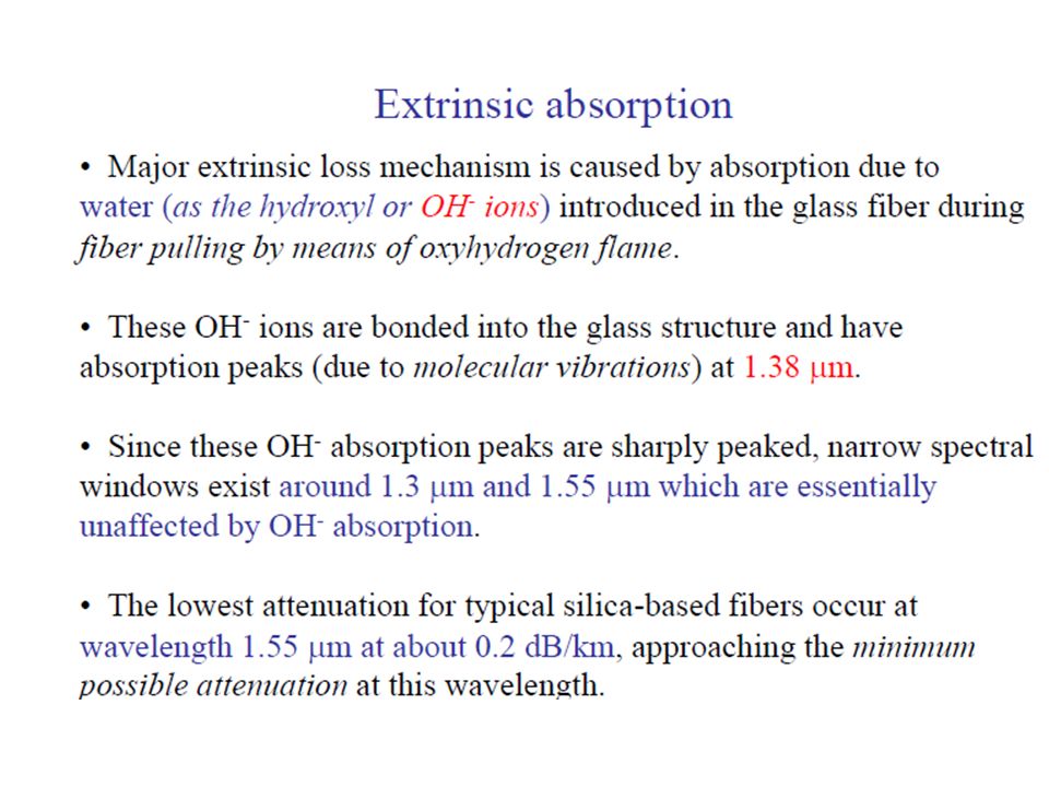
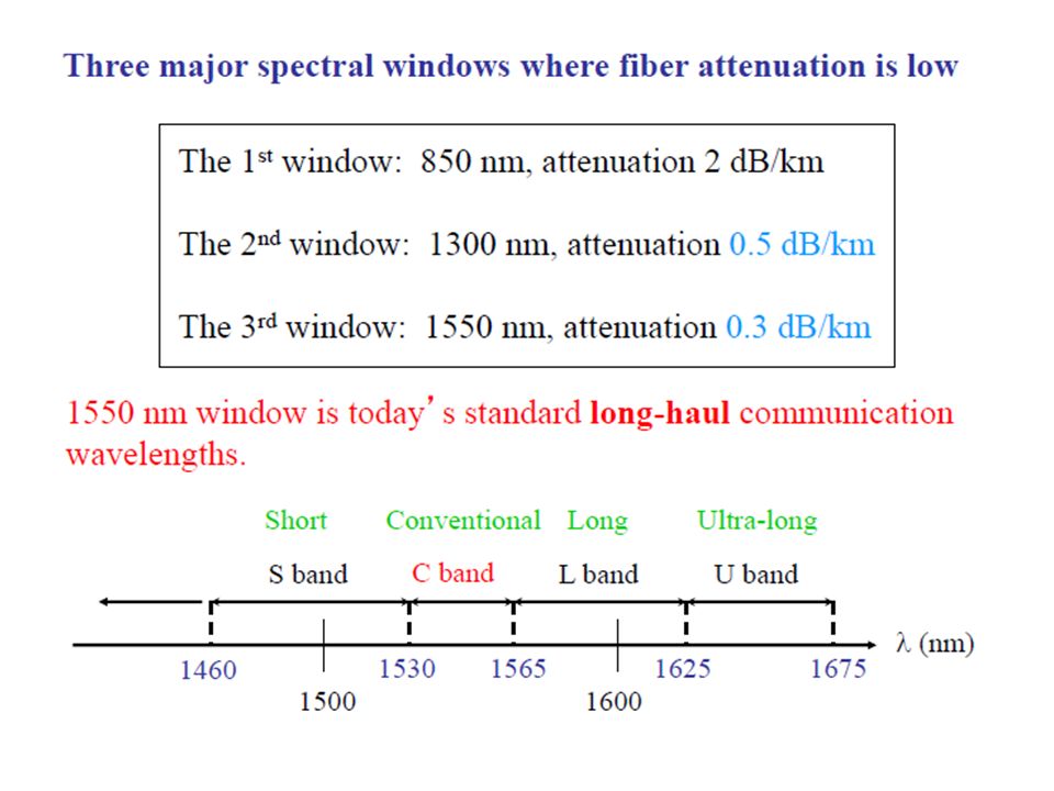
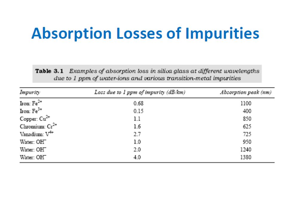
Extrinsic Absorption: Caused by impurities within the glass A- Extrinsic Absorption (OH ions): Caused by dissolved water in the glass, as the Hydroxy or (OH) ion. In this case absorption due the same fundamental processes between (2700 nm, and 4200 nm) gives rise to so called absorption overtones at 1380, 950, 720 nm. Typically a 1 part per million impurity level causes 1 dB/ km of attenuation at 950 nm. 9/12/2015 16
 gives rise to so called absorption overtones at 1380, 950, 720 nm. Typically a 1 part per million impurity level causes 1 dB/ km of attenuation at 950 nm. 9/12/")
17
B- Extrinsic Absorption (metallic ions): For some of the more common metallic impurities in silica fiber, the table shows the peak attenuation wavelength caused by impurity concentration of 1 in 10 9. Modern fabrication techniques can reduce impurity levels below 1 part in 10 10 9/12/2015 17 **Extrinsic absorption is much more significant than intrinsic

19
9/12/2015 19

23
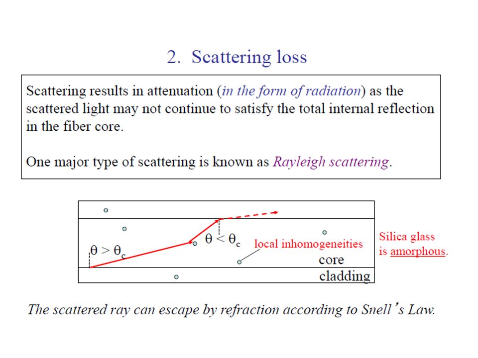
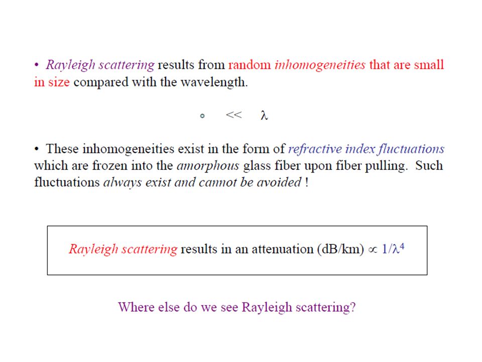
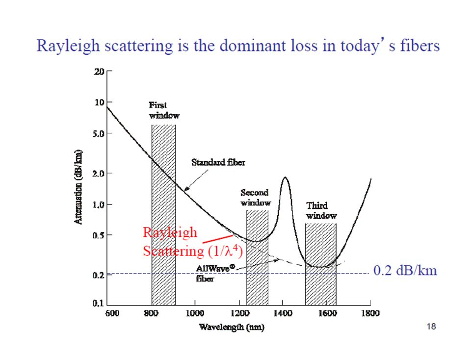
9/12/201523 Scattering - Linear Scattering Losses Scattering is a process whereby all or some of the optical power in a mode id transferred into another mode. Frequently causes attenuation, since the transfer is often to a mode that does not propagate well. (also called a leaky or radiation mode). o Two major type: 1. Rayleigh 2. Mie scattering
. o Two major type: 1. Rayleigh 2. Mie scattering.")
24
9/12/201524 Raleigh Scattering - most common form of scattering ▪ caused by microscopic non-uniformities making light rays partially scatter ▪ nearly 90% of total attenuation is attributed to Raleigh Scattering ▪ becomes important when wavelengths are short - comparable to size of the structures in the glass: long wavelengths are less affected than short wavelengths ▪ Raleigh scattering causes the sky to be blue, since only the short (blue) wavelengths are significantly scattered by the air molecules.)
 wavelengths are significantly scattered by the air molecules.)")
25
9/12/201525 The loss (dB/km) can be approximated by the formula below with λ in µm;
 can be approximated by the formula below with λ in µm;")
29
9/12/201529 Mie Scattering ▪ caused in inhomogeneities which are comparable in size to the guided wavelength. ▪ These result from the non-perfect cylindrical structure of the waveguide and may be caused by fiber imperfections such as irregularities in the core-cladding interface, core-cladding refractive index differences along the fiber length, diameter fluctuations, strains and bubbles.

30
9/12/201530 Non linear scattering causes the power from one mode to be transferred in either the forward or backward direction to the same or other modes, at the different frequency. The most important types are; 1. Stimulated Brillouin 2. Raman scattering Both are usually only observed at high optical power density in long single mode fibers

31
Stimulated Brillouin Scattering (SBS) ▪ another way to increase SBS threshold is to phase dither the output of the external modulator - see Graphs below. A high frequency (usually 2 x highest frequency) is imposed at the external modulator. ▪ Erbium-Doped Fiber Amplifiers (EDFAs) reduces the SBS threshold (in Watts) by the number of amplifiers. 9/12/2015 31
 is imposed at the external modulator. ▪ Erbium-Doped Fiber Amplifiers (EDFAs) reduces the SBS threshold (in Watts) by the number of amplifiers. 9/12/")
32
Stimulated Raman Scattering (SRS) ▪ much less of a problem than SBS ▪ threshold is close to 1 Watt, nearly a thousand times higher than SBS ▪ with an EDFA having an output power of 200mW, SRS threshold will be reached after 5 amplifiers. Recall that threshold drops with each amplifier. ▪ Shorter wavelengths are robbed of power and fed to longer wavelengths. (See Graphs below) 9/12/2015 32
 9/12/")
33
dB/ km P B = 4.4 PR=PR= Threshold optical power for Brillouin and Raman scattering. d=core diameter, v =source bandwidth, = attenuation

34
Given: Input Power = 1mW Length = 1.3km Attenuation Coefficient, = 0.6dB/km Find: Output Power Solution: P(z) = Po10 - z/10 = 1mW10 -0.6·1.3/10 = 836 W 9/12/2015 34 1.3km Pin = 1mWPout = ? = 0.6B/km

35
Given: Input Power = 1mW Length = 2.6km Attenuation Coefficient, = 0.6dB/km Find: Output Power 9/12/2015 35 2.6km Pin = 1mWPout = ? = 0.6B/km Answer: Pout = 698 W

36
Given: Input Power = 1mW Output Power = 250 W Length = 2km Find: Attenuation Coefficient, 9/12/2015 36 2km Pin = 1mW Pout = 250 W = ? Answer: = 3dB/km

37
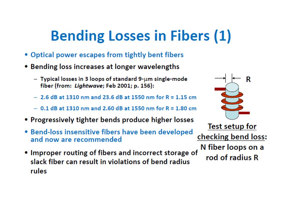
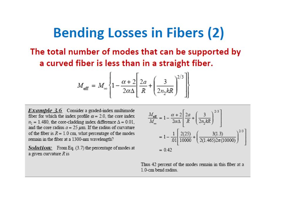
microbending - result of microscopic imperfections in the geometry of the fiber macrobending - fiber bending with diameters on the order of centimeters (usually unnoticeable if the radius of the bend is larger than 10 cm) 9/12/201537
 9/12/201537")
41
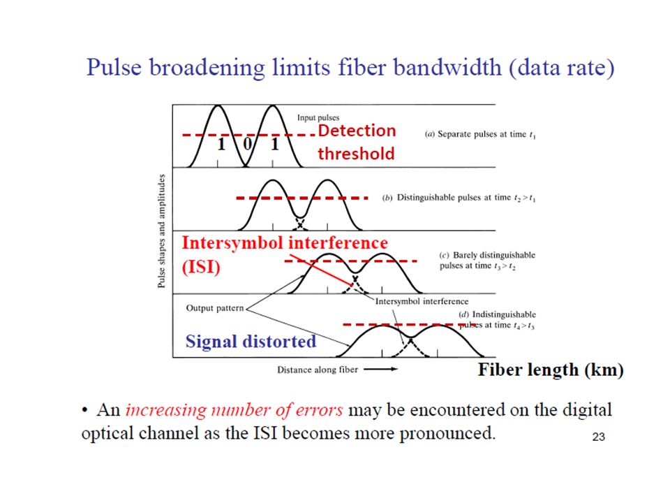
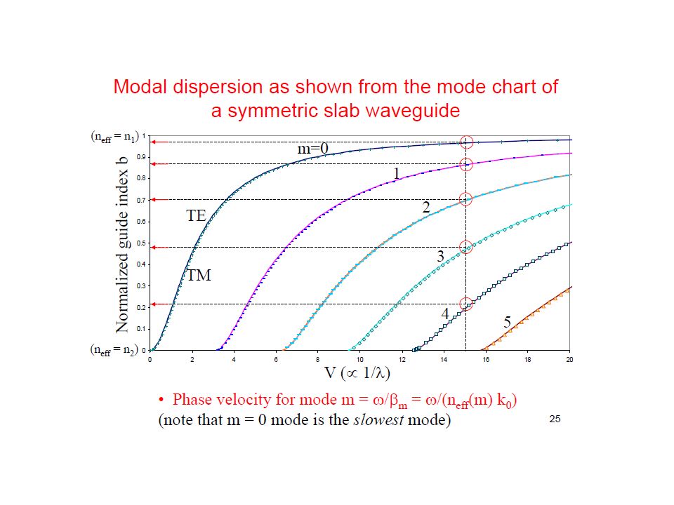
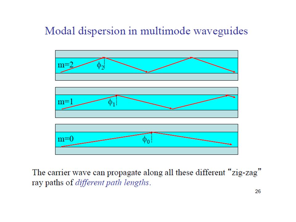
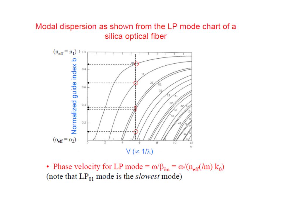
Different modes take a different amount of time to arrive at the receiver. Result is a spread-out signal Graded Index Fiber prior discussion concerned with Step Index Fiber GRIN fiber is designed so that all modes travel at nearly the same speed GRIN fiber core has a parabolic index of refraction 9/12/201541

42
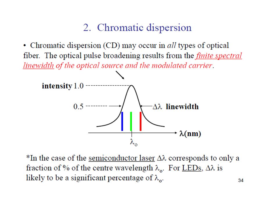
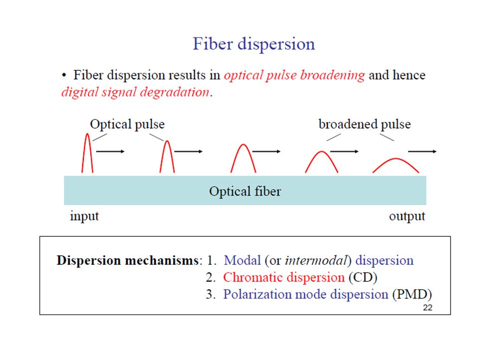
Dispersion - spreading of light pulses in a fiber limits bandwidth most important types ▪ Intramodal or chromatic dispersion ▪ material dispersion ▪ waveguide dispersion ▪ profile dispersion ▪ Intermodal/multimode dispersion ▪ polarization mode dispersion (PMD) 9/12/2015 42
 9/12/")
43
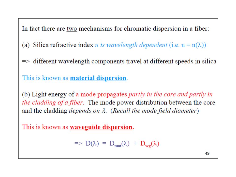
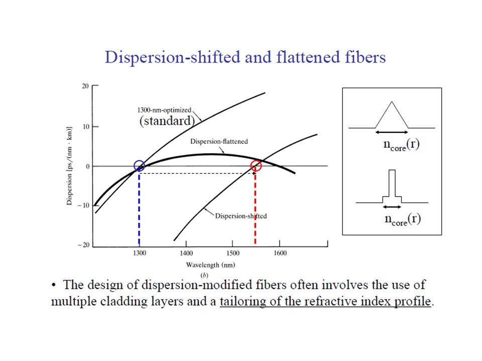
Chromatic Dispersion caused by different wavelengths traveling at different speeds is the result of material dispersion, waveguide dispersion or profile dispersion for the fiber characteristics shown at right, chromatic dispersion goes to zero at 1550 nm (Dispersion-Shifted Fiber) For a light-source with a narrow spectral emission, the bandwidth of the fiber will be very large. (FWHM = Full Width Half Maximum) 9/12/2015 43
 9/12/")
52
Material Dispersion - caused by the fact that different wavelengths travel at different speeds through a fiber, even in the same mode. Amount of Material Dispersion Determined by: range of light wavelengths injected into the fiber (spectral width of source) ▪ LEDs (35 - 170 nm) ▪ Lasers (< 5 nm) center operating wavelength of the source ▪ around 850 nm: longer wavelengths (red) travel faster than shorter wavelengths (blue) ▪ around 1550 nm: the situation is reversed - zero dispersion occurs where the wavelengths travel the same speed, around 1310 nm Material dispersion greatly affects single- mode fibers. In multimode fibers, multimode dispersion usually dominates. 9/12/2015 52
 ▪ LEDs ( nm) ▪ Lasers (< 5 nm) center operating wavelength of the source ▪ around 850 nm: longer wavelengths (red) travel faster than shorter wavelengths (blue) ▪ around 1550 nm: the situation is reversed - zero dispersion occurs where the wavelengths travel the same speed, around 1310 nm Material dispersion greatly affects single- mode fibers. In multimode fibers, multimode dispersion usually dominates. 9/12/")
53
Can be approximated by: [λ ZD = zero dispersion wavelength (λ ZD = 1276nm for pure silica or can be approximated as 1300nm)] 9/12/2015 53
![ Can be approximated by: [λ ZD = zero dispersion wavelength (λ ZD = 1276nm for pure silica or can be approximated as 1300nm)] 9/12/](http://images.slideplayer.com/23/6873732/slides/slide_53.jpg " Can be approximated by: [λ ZD = zero dispersion wavelength (λ ZD = 1276nm for pure silica or can be approximated as 1300nm)] 9/12/")
54
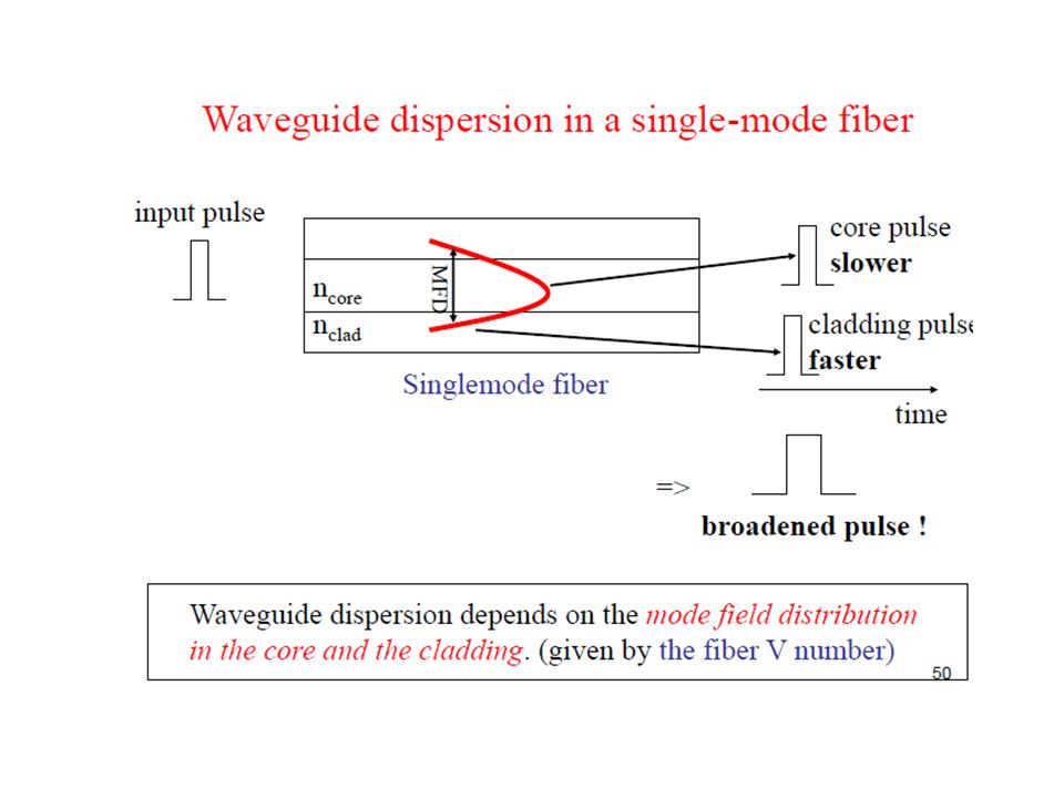
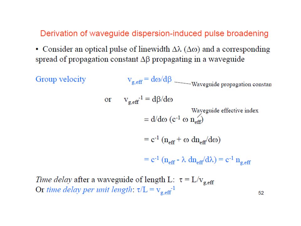
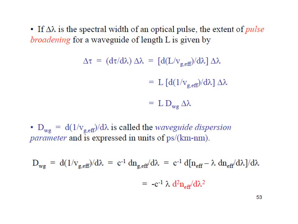
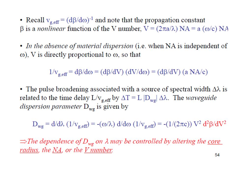
Waveguide Dispersion, D W occurs because optical energy travels in both the core and cladding at slightly different speeds. A greater concern for single-mode fibers than for multimode fibers Profile Dispersion the refractive indices of the core and cladding are described by a refractive index profile since the refractive index of a graded index fiber varies, it causes a variation in the propagation of different wavelengths profile dispersion is more significant in multimode fibers that in single-mode fibers 9/12/2015 54

55
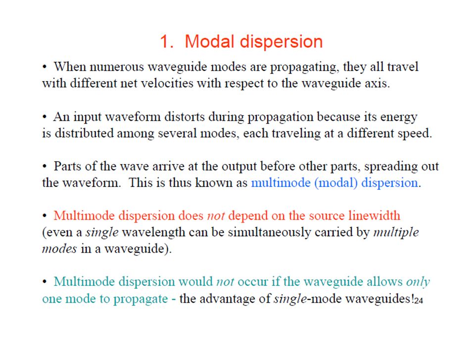
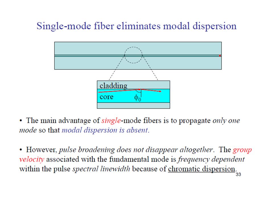
Multimode Dispersion (also Modal Dispersion) caused by different modes traveling at different speeds characteristic of multimode fiber only can be minimized by: ▪ using a smaller core diameter ▪ using graded-index fiber ▪ use single-mode fiber - single-mode fiber is only single-mode at wavelengths greater than the cutoff wavelength When multimode dispersion is present, it usually dominates to the point that other types of dispersion can be ignored. 9/12/2015 55 Intermodal dispersion formula, L=fiber length, C= speed of light, n 1 =core refractive index

66
The total chromatic dispersion can be obtained by adding D M and D W i.e. (D M +D W )∆λ. Normally D M > D W in the range of wavelengths 800 – 900nm. Therefore, waveguide dispersion can be neglected except for systems operating in the region 1200nm – 1600nm. 9/12/2015 66
∆λ. Normally D M > D W in the range of wavelengths 800 – 900nm. Therefore, waveguide dispersion can be neglected except for systems operating in the region 1200nm – 1600nm. 9/12/")
69
The overall dispersion in the fibers comprise both intramodal and intermodal terms. The total rms broadening σ T is given by: σ T =(σ c 2 + σ n 2 ) 1/2 where σ c is the intramodal or chromatic broadening and σ n is the intermodal broadening (i.e. σ s for multimode step index fiber and σ g for multimode graded index fiber) However, since waveguide dispersion is generally negligible compared with material dispersion in multimode fibers, the σ c = σ m. 9/12/2015 69
 1/2 where σ c is the intramodal or chromatic broadening and σ n is the intermodal broadening (i.e. σ s for multimode step index fiber and σ g for multimode graded index fiber) However, since waveguide dispersion is generally negligible compared with material dispersion in multimode fibers, the σ c = σ m. 9/12/")
70
Complex optical effect that occurs in single- mode fibers Most single-mode fibers support two perpendicular polarizations of the original transmitted signal Because of imperfections, the two polarizations do not travel at the same speed. The difference in arrival times is known as PMD (ps/km ) 9/12/2015 70
 9/12/")
Similar presentations