Download presentation
Presentation is loading. Please wait.

1
MBW-MQW in the LHC Considerations on expected life and available options Presented by P. Fessia Fluka analysis: Francesco Cerutti, Anton Lechner, Eleftherios Skordis Collimation input: Rodrick Bruce, Stefano Redaelli, Belen Maria Salvachua Ferrando, Elena Quaranta MNC team: Paolo Fessia, Pierre Alexandre Thonet, D. Tommasini Power Converter: Hugues Thiesen Optics: Massimo Giovannozzi MME design office: L. Favre, T. Sahner VSC: Eric Page, N. Zelko

2
Summary The magnets The expected dose Evaluation of the magnet lifetime Protective actions – Shielding – Optics changes The present “final” picture Actions, planning and risks

3
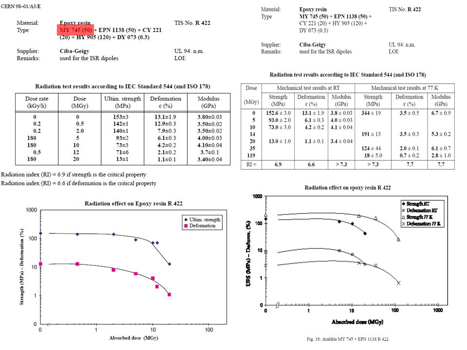
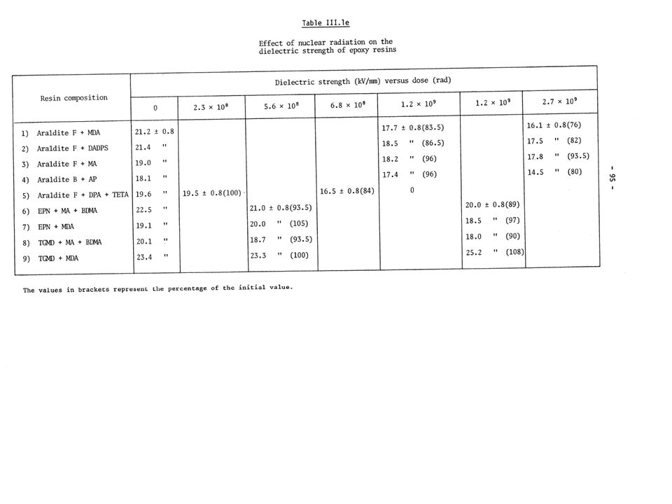
MQW point 7 and 3 CharacteristicsRQ4.L R7 RQ5.L R7 RQT4. L7 RQT5. L7 RQT4. R7 RQT5. R7 RQ4.L R3 RQ5.L R3 RQT4. L3 RQT5.L3RQT4.R3RQT5.R3 I ultimate (from layout database) [A] 810 600 810 600 Voltage I ultimate [V]3813832931272945145238344239 I 7 TeV (Fidel report) [A]5986101511715117561593313441313441 Voltage I 7 TeV [V]282289828231333120312229 Number magnet in series in circuit 10 1111 1111 Turn/magnet171 Estimated ultimate inter-turn voltage [V] 0.22 0.170.180.160.170.26 0.220.20.250.23 Estimated inter-turn voltage at 7 TeV [V] 0.160.170.050.010.050.010.180.190.120.180.130.17 Estimated inter layer voltage Same as inter turn Insulation thickness inter turn 2X(2X0.25) mm=1 mm glass tape Circuit energy ultimate [Kj] 15416499991541649999 Circuit energy 7 TeV [Kj]84930.60.010.60.0174882.55 5 Ground insulation1X(2X0.25) mm+3X(2X0.25)=2 mm Resin usedEPN1138 42%+ GY 6004 42% + CY 221 16% + HY 905 100 %+ 30ml DY 073 Dielectric resin> 20 kV/mm
 [A] Voltage I ultimate [V] I 7 TeV (Fidel report) [A] Voltage I 7 TeV [V] Number magnet in series in circuit Turn/magnet171 Estimated ultimate inter-turn voltage [V] Estimated inter-turn voltage at 7 TeV [V] Estimated inter layer voltage Same as inter turn Insulation thickness inter turn 2X(2X0.25) mm=1 mm glass tape Circuit energy ultimate [Kj] Circuit energy 7 TeV [Kj] Ground insulation1X(2X0.25) mm+3X(2X0.25)=2 mm Resin usedEPN %+ GY % + CY % + HY %+ 30ml DY 073 Dielectric resin> 20 kV/mm.")
4
MBW point 7 and 3 Characteristics RD34.LR7RD34.LR3 I ultimate [A] (layout database)810 Voltage I ultimate [V]440700 I 7 TeV (Fidel report)643 Voltage I 7 TeV350556 Number magnet in series in circuit812 Turn/magnet84 Estimated ultimate inter-turn voltage [V]0.650.7 Estimated inter-turn voltage 7 TeV [V]0.520.55 Estimated ultimate inter layer voltage [V]9.29.7 Estimated inter layer voltage 7 TeV [V]7.27.8 Circuit energy ultimate [Kj]472793 Circuit energy 7 TeV [Kj]297500 Insulation inter turn [mm]2X(2X0.15)=0.6 glass tape Insulation inter layer [mm]2X(2X0.15)+2X(2X0.15)+1(glass cloth) =1.6 glass tape Ground insulation2X(2X0.15)+1.5(0.15Xx)=1.8 glass tape Resin usedEPC-1: resin ED-16 100 Hardener MA 2.28 K Plasticizer MGF-9 20 TEa accelerant 0.5 Dielectric resinUnknwown (>>15kV/mm)
![MBW point 7 and 3 Characteristics RD34.LR7RD34.LR3 I ultimate [A] (layout database)810 Voltage I ultimate [V] I 7 TeV (Fidel report)643 Voltage I 7 TeV Number magnet in series in circuit812 Turn/magnet84 Estimated ultimate inter-turn voltage [V] Estimated inter-turn voltage 7 TeV [V] Estimated ultimate inter layer voltage [V] Estimated inter layer voltage 7 TeV [V] Circuit energy ultimate [Kj] Circuit energy 7 TeV [Kj] Insulation inter turn [mm]2X(2X0.15)=0.6 glass tape Insulation inter layer [mm]2X(2X0.15)+2X(2X0.15)+1(glass cloth) =1.6 glass tape Ground insulation2X(2X0.15)+1.5(0.15Xx)=1.8 glass tape Resin usedEPC-1: resin ED Hardener MA 2.28 K Plasticizer MGF-9 20 TEa accelerant 0.5 Dielectric resinUnknwown (>>15kV/mm)](http://images.slideplayer.com/23/6832364/slides/slide_4.jpg "MBW point 7 and 3 Characteristics RD34.LR7RD34.LR3 I ultimate [A] (layout database)810 Voltage I ultimate [V] I 7 TeV (Fidel report)643 Voltage I 7 TeV Number magnet in series in circuit812 Turn/magnet84 Estimated ultimate inter-turn voltage [V] Estimated inter-turn voltage 7 TeV [V] Estimated ultimate inter layer voltage [V] Estimated inter layer voltage 7 TeV [V] Circuit energy ultimate [Kj] Circuit energy 7 TeV [Kj] Insulation inter turn [mm]2X(2X0.15)=0.6 glass tape Insulation inter layer [mm]2X(2X0.15)+2X(2X0.15)+1(glass cloth) =1.6 glass tape Ground insulation2X(2X0.15)+1.5(0.15Xx)=1.8 glass tape Resin usedEPC-1: resin ED Hardener MA 2.28 K Plasticizer MGF-9 20 TEa accelerant 0.5 Dielectric resinUnknwown (>>15kV/mm)")
7
Analysis exp. data point 3 and point 7 RP survey IP3 RP survey IP7 7R/7L=B2/B1 3R/3L=B2/B1 297.4 kGy 8.0 kGy 1.6 kGy 6.7 kGy 81.7 kGy 1.3 kGy 2.3 kGy fallen off (487.3 kGy) 25.7 kGy 100.4 kGy 59.6 kGy > 500 kGy 43.7 kGy 19.1 kGy 1/6 1/10 1/3 1 397.5 kGy 119.8 kGy> 500 kGy 106.3 kGy 487.3 kGy 469.1 kGy297.4 kGy 329.4 kGy 15.7 kGy 6.3 kGy 18.0 kGy 9.2 kGy 4.4 kGy 5.5 kGy 2.3 kGy 1/100 1/20 1 1
 25.7 kGy kGy 59.6 kGy > 500 kGy 43.7 kGy 19.1 kGy 1/6 1/10 1/ kGy kGy> 500 kGy kGy kGy kGy297.4 kGy kGy 15.7 kGy 6.3 kGy 18.0 kGy 9.2 kGy 4.4 kGy 5.5 kGy 2.3 kGy 1/100 1/")
8
Point 3 and 7 coil magnet damage estimation MQWMBW From 10 to 20 MGyFrom 40 to 60 MGy From 20 to 50 MGyFrom 60 to 80 Mgy Larger than 50 MGyLarger than 80 MGy IP 7 IP 3

9
Screen design - For max effectiveness we have to target the higher possible density candidate therefore W, or better the alloys for machining - Magnetic properties can be an issue. Measurement being performed - Possible material staging along the MQW magnet length under study Inermet IT180 Nominal density18 W content %95 BalanceNi,Cu E-modulus360 GPa

10
MQW shielding effect Normalization: 1.15 10 16 p (50 fb -1 ) Beam 2
 Beam 2")
11
MBWA - MBWB Peak Dose profile MBW.B6R7 Flanges + Protection Beam 2 MBW.A6R7 Flanges + Protection Beam 2 MBW.A6R7 with Flanges Beam 2 Normalization: 1.15 10 16 p (50 fb -1 ) MBW.B6R7 With Flanges Beam 2
 MBW.B6R7 With Flanges Beam 2")
12
ABS Optic change proposal point 7 discussed and agreed as possible with M. Giovannozzi (it needs verification)
.")
13
Action LS1 Dose [MGy] for integrated luminosity 150 fb^-1Action LS2 Dose [MGy] for integrated luminosityy350 fb^-1Action LS3 Dose [MGy] for integrated luminosity3000 fb^-1Action during HL-LHC exploitation RLRLRLRLRLRLRL MQWA.A4 0.40.5 0.91.2 7.411 MQWA.B4 0.30.8 0.71.9 6.416 MQWB.4 0.51.3 S1.21.8 S10.19 MQWA.C4 4.0 SS5.8 SS30 MQWA.D4 2.7 SS3.8 SS20 MQWA.E4 5.010.0SS7.214SS3773 R MQWA.A5 2.6 SS3.7 SS19 MQWA.B5 3.5 SS5.0 SS25 MQWB.5 4.1 SS5.9 SS30 MQWA.C5 1.94.9SS2.87.0SS1436 MQWA.D5SS 1.42.0done 3.34.7done 27.939.9 MQWA.E5SS 124.1done 2910done 24682RR MBW.A6SS 7.85.5done 1813done 155111RR MBW.B6SS 126.2done 3014done 248124RR Magnet damage with shielding point 3 and 7, W shielding peak dose scaling Limit reached in7R7L MQWA.E41500 fb^-1 MBW.B61500 fb^-12400 fb^-1 MBW.A61000 fb^-12000 fb^-1 IP 7 IP 3 Remove Action LS1 Dose [MGy] for integrated luminosity 150 fb^-1Action LS2 Dose [MGy] for integrated luminosity 350 fb^-1Action LS3 Dose [MGy] for integrated luminosity 3000 fb^-1 Action during HL-LHC exploitation RLRLRLRLRLRLRL MQWA.A4 0.00.1 0.2 1.01.9 MQWA.B4 0.1 0.2 1.02.1 MQWB.4 0.1 0.3 1.12.2 MQWA.C4 0.1 0.20.3 1.42.8 MQWA.D4 0.20.3 0.40.8 3.56.9 MQWA.E4 0.91.7SS1.22.5SS6.312 MQWA.A5 0.61.1SS0.81.6SS4.07.5 MQWA.B5 0.71.4SS1.02.0SS5.19.4 MQWB.5 1.73.3SS2.44.8SS1223 MQWA.C5 3.97.7SS5.611SS2953 MQWA.D5 0.91.9SS1.32.7SS6.813 MQWA.E5 1.73.5SS2.55.0SS1324 MBW.A6 1.02.0SS1.42.9SS7.314 MBW.B6 1.22.3SS1.73.3SS8.416 MBW.C6 1.63.3SS2.34.7SS123
![Action LS1 Dose [MGy] for integrated luminosity 150 fb^-1Action LS2 Dose [MGy] for integrated luminosityy350 fb^-1Action LS3 Dose [MGy] for integrated luminosity3000 fb^-1Action during HL-LHC exploitation RLRLRLRLRLRLRL MQWA.A MQWA.B MQWB S S10.19 MQWA.C4 4.0 SS5.8 SS30 MQWA.D4 2.7 SS3.8 SS20 MQWA.E SS7.214SS3773 R MQWA.A5 2.6 SS3.7 SS19 MQWA.B5 3.5 SS5.0 SS25 MQWB SS5.9 SS30 MQWA.C SS2.87.0SS1436 MQWA.D5SS done done MQWA.E5SS 124.1done 2910done 24682RR MBW.A6SS done 1813done RR MBW.B6SS 126.2done 3014done RR Magnet damage with shielding point 3 and 7, W shielding peak dose scaling Limit reached in7R7L MQWA.E41500 fb^-1 MBW.B61500 fb^ fb^-1 MBW.A61000 fb^ fb^-1 IP 7 IP 3 Remove Action LS1 Dose [MGy] for integrated luminosity 150 fb^-1Action LS2 Dose [MGy] for integrated luminosity 350 fb^-1Action LS3 Dose [MGy] for integrated luminosity 3000 fb^-1 Action during HL-LHC exploitation RLRLRLRLRLRLRL MQWA.A MQWA.B MQWB MQWA.C MQWA.D MQWA.E SS1.22.5SS6.312 MQWA.A SS0.81.6SS MQWA.B SS1.02.0SS MQWB SS2.44.8SS1223 MQWA.C SS5.611SS2953 MQWA.D SS1.32.7SS6.813 MQWA.E SS2.55.0SS1324 MBW.A SS1.42.9SS7.314 MBW.B SS1.73.3SS8.416 MBW.C SS2.34.7SS123](http://images.slideplayer.com/23/6832364/slides/slide_13.jpg "Action LS1 Dose [MGy] for integrated luminosity 150 fb^-1Action LS2 Dose [MGy] for integrated luminosityy350 fb^-1Action LS3 Dose [MGy] for integrated luminosity3000 fb^-1Action during HL-LHC exploitation RLRLRLRLRLRLRL MQWA.A MQWA.B MQWB S S10.19 MQWA.C4 4.0 SS5.8 SS30 MQWA.D4 2.7 SS3.8 SS20 MQWA.E SS7.214SS3773 R MQWA.A5 2.6 SS3.7 SS19 MQWA.B5 3.5 SS5.0 SS25 MQWB SS5.9 SS30 MQWA.C SS2.87.0SS1436 MQWA.D5SS done done MQWA.E5SS 124.1done 2910done 24682RR MBW.A6SS done 1813done RR MBW.B6SS 126.2done 3014done RR Magnet damage with shielding point 3 and 7, W shielding peak dose scaling Limit reached in7R7L MQWA.E41500 fb^-1 MBW.B61500 fb^ fb^-1 MBW.A61000 fb^ fb^-1 IP 7 IP 3 Remove Action LS1 Dose [MGy] for integrated luminosity 150 fb^-1Action LS2 Dose [MGy] for integrated luminosity 350 fb^-1Action LS3 Dose [MGy] for integrated luminosity 3000 fb^-1 Action during HL-LHC exploitation RLRLRLRLRLRLRL MQWA.A MQWA.B MQWB MQWA.C MQWA.D MQWA.E SS1.22.5SS6.312 MQWA.A SS0.81.6SS MQWA.B SS1.02.0SS MQWB SS2.44.8SS1223 MQWA.C SS5.611SS2953 MQWA.D SS1.32.7SS6.813 MQWA.E SS2.55.0SS1324 MBW.A SS1.42.9SS7.314 MBW.B SS1.73.3SS8.416 MBW.C SS2.34.7SS123")
14
Conclusions I IP3IP7 LRLR Broken units no int Units to be modified Broken units Broken units no int. Units to be modified Broken units Broken units no int Units to be modified Broken units Broken units no int. Units to be modified Broken units LS1 MQW NA0 0 2 2 MBW NA0 0 2 2 LS2 MQW 070070070080 MBW 0300300NA00 0 LS3 MQW 000000100000 MBW 000000100000 HL- LHC MQW 400100901900 MBW 000000202202

15
Conclusion II The proposed screen allow reducing of a factor 3 the dose and limit the number of magnet at risk or surely damaged, see previous slides. Hp. to achieve the same reduction factor on the spacers The change of the optic in point 7 installing a long absorber is key to complete the protection The lifetime of these units could be affected by the new environmental condition of point 7 not discussed here

16
Conclusion III: actions The proposed shielding campaign should start in LS1 for effectiveness and ALARA Very high dose dosimeter shall be installed systematically in point 3 and 7 to check better benchmark computations and symmetry effect A campaign of irradiation of resins shall be performed with the real used resins and the relevant fillers in order to real know when the magnet will reach damage level For HL LHC 4 MBW shall be reassembled with saddle type heads. This will solve the issue without needing special development I suggest that we launch the program to build a NC magnet with extremely high radiation resistance (>300 MGy). It is and it will be more and more needed and today we do not have it in our capabilities and it will be key for future target areas development We need to check – For HL-LHC the MBW radiation dose along the straight part of the coil – The level of accumulated dose of the MBXW units – If any protecion can be added to on the beam line for the MQWA.E4 in point 7 R and 7 L
. It is and it will be more and more needed and today we do not have it in our capabilities and it will be key for future target areas development We need to check – For HL-LHC the MBW radiation dose along the straight part of the coil – The level of accumulated dose of the MBXW units – If any protecion can be added to on the beam line for the MQWA.E4 in point 7 R and 7 L.")
17
LONG VERSION

18
MQW coil resins Resin used componentEPN1138GY 6004CY 221HY 90530ml DY 073 percentage50 % 20 %120 %0.03 EPN 1138Novolac GY 6004DGEBA CY 221DGEBA HY 905 HPA DY 073flexibilizer

19
1 2 3 4 5 6 7 8 9 10 11

21
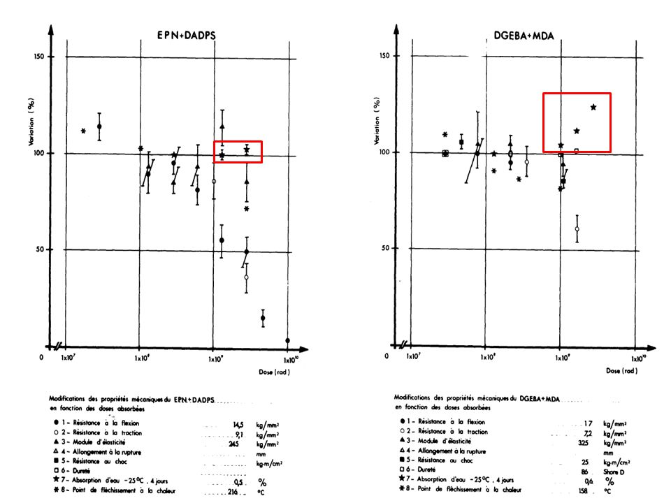
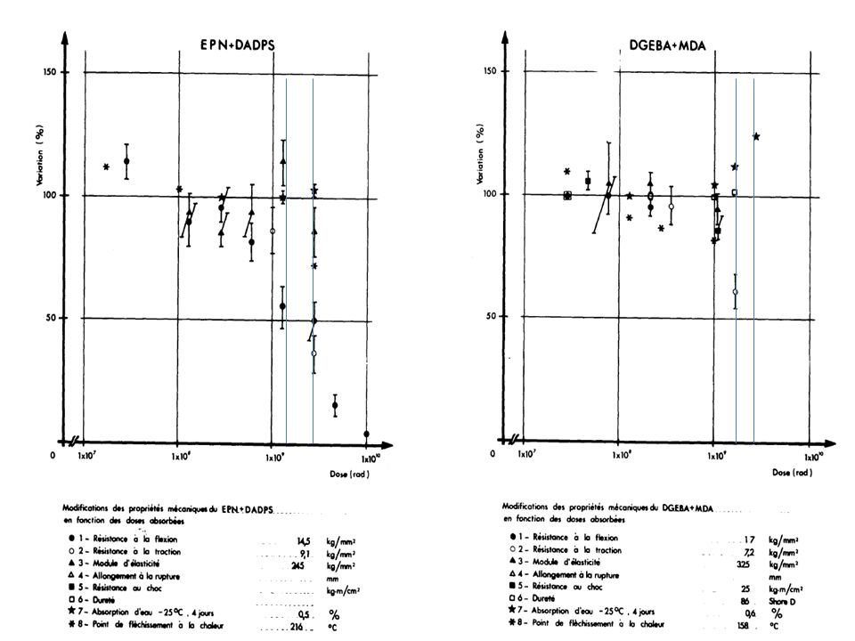
Different epoxy 28/07/201221 ResinsHardenersAdditives Composition (p.p.) Mix Temp (°C) Viscosity (cPs) Service life (mn) Fig Dose for 50% flex. (MGy) Dose Range (MGy) EDBAHMA 5.41.4 1 - 3 EDBAHMABDMA100-105-0.28045>1805.11.6 BECPMA 5.42.5 BECPMABDMA100-110-0.28040>1805.12.3 ECCMA 100-728020>2405.51.8 1 - 6 VCDMABDMA100-160-056020>1805.43.7 DADDMA 100-6580180>2405.45.5 DGEBA +EDGDPTETA 100-20-1225 5.211.3 1 - 2 DGEBATETADBP83-9-1750500few5.221.2 DGEBADADPS 100-35130601804.25.1 5 - 15 DGEBA +EDGDPMDA 100-20-3080 5.218.2 DGEBAMDA 100-2780100505.913.0 DGEBAMPDA 100-14.565200305.723.523 DGEBAAF 100-40100150305.2645.245 DGEBADDSABDMA100-130-180701205.24.2 5 - 15 DGEBANMABDMA100-80-180 1205.25.9 DGEBAMA 100-1006069>14405.237.1 DGEBAMABDMA 5.112.0 DGEBAMA BDMA + Po. Gl. 100-100-0.1-1060653005.2312.1 DGEBAAP 100-70120261805.213.0 DGPPDADPS 100-28130 5.68.2 5 - 15 DGPPMA 100-135120 5.313.0 EDTCMDA 100-2080 405.910.0 TGTPEDADPS 100-34125>20000 5.612.1 TGTPEMABDMA100-100-0.2125>15000 5.310.6 EPNDADPS 100-35100 305.623.5 20 - 40 EPNMDA 100-29100 355.1037.2 EPNHPABDMA100-76-180 405.1013.0 10 - 20 EPNMABDMA100-105-0.580 1005.3+5.2515.0 EPNNMABDMA100-85-1100 805.1020.6 TGMDDADPS 100-4080 505.620.6 10 - 25 TGMDMABDMA100-136-0.560 305.311.4 TGMDNMABDMA100-110-180500205.818.0 TGPAPNMA 100-13780<20 5.823.5 DGAMPDA 100-2025 120-4205.723.5 20 - 30 DGANMA 100-115255 - 2030-57605.828.6 Legend Resin Linear aliphatic Cycloaliphatic Aromatic Hardener Aliphatic Amine Aromatic Amine Alicyclic Anhydride Aromatic Anhydride Aromatic > Cycloaliphatic > Linear Aliphatic Aliphatic amine harderner poor radio-resistance Aromatic amine hardener > Anhydride hardener H: Too high local concentration of benzene may induce steric hindrance disturbation Good radio-resistance even if Cl (tendence to capture n th ) Novolac: HIGH Radio-resistance Large nb of epoxy groups Density + rigidity Glycidyl-amine: HIGH R.-resistance Quaternary carbon weakness Ether group (R – O – R’) weakness Repl. by amina E. Fornasiere
 Dose Range (MGy) EDBAHMA EDBAHMABDMA > BECPMA BECPMABDMA > ECCMA > VCDMABDMA > DADDMA > DGEBA +EDGDPTETA DGEBATETADBP few DGEBADADPS DGEBA +EDGDPMDA DGEBAMDA DGEBAMPDA DGEBAAF DGEBADDSABDMA DGEBANMABDMA DGEBAMA > DGEBAMABDMA DGEBAMA BDMA + Po. Gl DGEBAAP DGPPDADPS DGPPMA EDTCMDA TGTPEDADPS > TGTPEMABDMA > EPNDADPS EPNMDA EPNHPABDMA EPNMABDMA EPNNMABDMA TGMDDADPS TGMDMABDMA TGMDNMABDMA TGPAPNMA < DGAMPDA DGANMA Legend Resin Linear aliphatic Cycloaliphatic Aromatic Hardener Aliphatic Amine Aromatic Amine Alicyclic Anhydride Aromatic Anhydride Aromatic > Cycloaliphatic > Linear Aliphatic Aliphatic amine harderner poor radio-resistance Aromatic amine hardener > Anhydride hardener H: Too high local concentration of benzene may induce steric hindrance disturbation Good radio-resistance even if Cl (tendence to capture n th ) Novolac: HIGH Radio-resistance Large nb of epoxy groups Density + rigidity Glycidyl-amine: HIGH R.-resistance Quaternary carbon weakness Ether group (R – O – R’) weakness Repl. by amina E. Fornasiere.")
22
EPN 1138CY 222 (similar to CY221) MY745 replaced by GY6004
 MY745 replaced by GY6004")
23
Filler contribution 28/07/201223 ResinsHardenersAdditivesFiller Composition (p.p.) Fig Dose for 50% flex. (MGy) Dose Range (MGy) DGEBAMDA Papier100-27-2005.141.31 - 2 DGEBAMDA Silice100-27-2005.1410 10 - 15 DGEBAMDA Silice100-27-2005.1811.4 DGEBAMDA Silice (5 micron)100-27-205.1614.8 DGEBAMDA Silice (20 micron)100-27-205.1614.8 DGEBAMDA Silice (40 micron)100-27-205.1614.6 DGEBAMDA Silice (40 micron)100-27-2005.1712.1 DGEBAHPABDMASilice (40 micron)100-80-2-2005.17<10 DGEBAMDA Aérosil + Sulphate de Barium 100-27-2-1505.1415.815 DGEBAMDA Magnésie100-27-1205.1418 DGEBAMDA Graphite100-27-604.626.8 25 - 30 DGEBAMDA Graphite100-27-605.1430.5 (DGEBAMDA Alumine100-27-2204.723.5) 20 - 50 DGEBAMDA Alumine100-27-2205.1451.7 DGEBAMDA Alumine100-27-1005.1520.6 DGEBAMDA Alumine100-27-2205.1542.5 DGEBAMDA Fibre de verre100-27-505.1982 80 - 100 DGEBAMDA Fibre de verre100-27-605.18100 EPNMDA Fibre de verre100-29-505.19>100 TGMDMDA Fibre de silice100-41-505.20>100 TGMDDADPS Fibre de silice100-40-505.20>100 Legend Resin Linear aliphatic Cycloaliphatic Aromatic Hardener Aliphatic Amine Aromatic Amine Alicyclic Anhydride Aromatic Anhydride Paper [cellulose (C 6 H 10 O 5 ) n ] Strong decrease of radio-resistance 2 Categories of fillers: 1.Powder fillers 2.Glass/Silice fibers The bigger the powder, the more radio-resistant Hardener choice not influenced by filler High r.-resistance for Graphite and Alumina The more fillers, the more radio-resistant Best Radio-Resistant materials are obtain with Glass/Silice (influence of boron) fibers and aromatic resins (Novolac and glycidyl-amine) E. Fornasiere
 Dose Range (MGy) DGEBAMDA Papier DGEBAMDA Silice DGEBAMDA Silice DGEBAMDA Silice (5 micron) DGEBAMDA Silice (20 micron) DGEBAMDA Silice (40 micron) DGEBAMDA Silice (40 micron) DGEBAHPABDMASilice (40 micron) <10 DGEBAMDA Aérosil + Sulphate de Barium DGEBAMDA Magnésie DGEBAMDA Graphite DGEBAMDA Graphite (DGEBAMDA Alumine ) DGEBAMDA Alumine DGEBAMDA Alumine DGEBAMDA Alumine DGEBAMDA Fibre de verre DGEBAMDA Fibre de verre EPNMDA Fibre de verre >100 TGMDMDA Fibre de silice >100 TGMDDADPS Fibre de silice >100 Legend Resin Linear aliphatic Cycloaliphatic Aromatic Hardener Aliphatic Amine Aromatic Amine Alicyclic Anhydride Aromatic Anhydride Paper [cellulose (C 6 H 10 O 5 ) n ] Strong decrease of radio-resistance 2 Categories of fillers: 1.Powder fillers 2.Glass/Silice fibers The bigger the powder, the more radio-resistant Hardener choice not influenced by filler High r.-resistance for Graphite and Alumina The more fillers, the more radio-resistant Best Radio-Resistant materials are obtain with Glass/Silice (influence of boron) fibers and aromatic resins (Novolac and glycidyl-amine) E. Fornasiere.")
24
EPN 1138 with fillerCY 222 (similar to CY221) with filler MY745 replaced by GY6004 with fillerOther DGBA with filler MQW -The pure resin mix used shall keep substantial mechanical properties at least till 15-20 MGy -Presence of glass fibre shall increase the substantial mechanical properties at least to 40-50 MGy
 with filler MY745 replaced by GY6004 with fillerOther DGBA with filler MQW -The pure resin mix used shall keep substantial mechanical properties at least till MGy -Presence of glass fibre shall increase the substantial mechanical properties at least to MGy")
25
Spacers resins Composition – HD polyethylene pipes filled with IngredientQuantityDescription EPON 82622 kgLow viscosity, liquid bisphenol A based epoxy resin. RP 15003kgTetramine hardener MIN-SIL 120 F 17 kgFused silica particles 50% diameter smaller than 0.044 mm Assume a limit of 20 MGy

26
MBW BINP used resin. We looked at molecule and there is good indication that it should radiation hard as witnessed by the tests and we assume stresses of the order of 10 MPa MBW -The pure resin mix used shall keep substantial mechanical properties at least till 50-60 (10 MPa) -Presence of fibre glass should probably extend life till 70-80 MGy
 -Presence of fibre glass should probably extend life till MGy.")
27
Type of deposition map Dose (MGy) Normalization: 1.15 10 16 p (30-50 fb -1 ). Computations with E 6.5 TeV relaxed collimator settings Dose (MGy)
.")
28
Analysis exp. data point 3 and point 7 RP survey IP3 RP survey IP7 7R/7L=B2/B1 3R/3L=B2/B1 297.4 kGy 8.0 kGy 1.6 kGy 6.7 kGy 81.7 kGy 1.3 kGy 2.3 kGy fallen off (487.3 kGy) 25.7 kGy 100.4 kGy 59.6 kGy > 500 kGy 43.7 kGy 19.1 kGy 1/6 1/10 1/3 1 397.5 kGy 119.8 kGy> 500 kGy 106.3 kGy 487.3 kGy 469.1 kGy297.4 kGy 329.4 kGy 15.7 kGy 6.3 kGy 18.0 kGy 9.2 kGy 4.4 kGy 5.5 kGy 2.3 kGy 1/100 1/20 1 1
 25.7 kGy kGy 59.6 kGy > 500 kGy 43.7 kGy 19.1 kGy 1/6 1/10 1/ kGy kGy> 500 kGy kGy kGy kGy297.4 kGy kGy 15.7 kGy 6.3 kGy 18.0 kGy 9.2 kGy 4.4 kGy 5.5 kGy 2.3 kGy 1/100 1/")
29
Point 3 and 7 coil magnet damage estimation MQWMBW From 10 to 20 MGyFrom 40 to 60 MGy From 20 to 50 MGyFrom 60 to 80 Mgy Larger than 50 MGyLarger than 80 MGy IP 7 IP 3

30
Screen design - For max effectiveness we have to target the higher possible density candidate therefore W, or better the alloys for machining - Magnetic properties can be an issue. Measurement being performed - Possible material staging along the MQW magnet length under study Inermet IT180 Nominal density18 W content %95 BalanceNi,Cu E-modulus360 GPa

31
MQW shielding effect Normalization: 1.15 10 16 p (50 fb -1 ) Beam 2
 Beam 2")
32
MBWA - MBWB Peak Dose profile MBW.B6R7 Flanges + Protection Beam 2 MBW.A6R7 Flanges + Protection Beam 2 MBW.A6R7 with Flanges Beam 2 Normalization: 1.15 10 16 p (50 fb -1 ) MBW.B6R7 With Flanges Beam 2
 MBW.B6R7 With Flanges Beam 2")
33
ABS Optic change proposal point 7 discussed and agreed as possible with M. Giovannozzi (it needs verification)
.")
34
Action LS1 Dose [MGy] for integrated luminosity 150 fb^-1Action LS2 Dose [MGy] for integrated luminosityy350 fb^-1Action LS3 Dose [MGy] for integrated luminosity3000 fb^-1Action during HL-LHC exploitation RLRLRLRLRLRLRL MQWA.A4 0.40.5 0.91.2 7.411 MQWA.B4 0.30.8 0.71.9 6.416 MQWB.4 0.51.3 S1.21.8 S10.19 MQWA.C4 4.0 SS5.8 SS30 MQWA.D4 2.7 SS3.8 SS20 MQWA.E4 5.010.0SS7.214SS3773 R MQWA.A5 2.6 SS3.7 SS19 MQWA.B5 3.5 SS5.0 SS25 MQWB.5 4.1 SS5.9 SS30 MQWA.C5 1.94.9SS2.87.0SS1436 MQWA.D5SS 1.42.0done 3.34.7done 27.939.9 MQWA.E5SS 124.1done 2910done 24682RR MBW.A6SS 7.85.5done 1813done 155111RR MBW.B6SS 126.2done 3014done 248124RR Magnet damage with shielding point 3 and 7, W shielding peak dose scaling Limit reached in7R7L MQWA.E41500 fb^-1 MBW.B61500 fb^-12400 fb^-1 MBW.A61000 fb^-12000 fb^-1 IP 7 IP 3 Remove Action LS1 Dose [MGy] for integrated luminosity 150 fb^-1Action LS2 Dose [MGy] for integrated luminosity 350 fb^-1Action LS3 Dose [MGy] for integrated luminosity 3000 fb^-1 Action during HL-LHC exploitation RLRLRLRLRLRLRL MQWA.A4 0.00.1 0.2 1.01.9 MQWA.B4 0.1 0.2 1.02.1 MQWB.4 0.1 0.3 1.12.2 MQWA.C4 0.1 0.20.3 1.42.8 MQWA.D4 0.20.3 0.40.8 3.56.9 MQWA.E4 0.91.7SS1.22.5SS6.312 MQWA.A5 0.61.1SS0.81.6SS4.07.5 MQWA.B5 0.71.4SS1.02.0SS5.19.4 MQWB.5 1.73.3SS2.44.8SS1223 MQWA.C5 3.97.7SS5.611SS2953 MQWA.D5 0.91.9SS1.32.7SS6.813 MQWA.E5 1.73.5SS2.55.0SS1324 MBW.A6 1.02.0SS1.42.9SS7.314 MBW.B6 1.22.3SS1.73.3SS8.416 MBW.C6 1.63.3SS2.34.7SS123
![Action LS1 Dose [MGy] for integrated luminosity 150 fb^-1Action LS2 Dose [MGy] for integrated luminosityy350 fb^-1Action LS3 Dose [MGy] for integrated luminosity3000 fb^-1Action during HL-LHC exploitation RLRLRLRLRLRLRL MQWA.A MQWA.B MQWB S S10.19 MQWA.C4 4.0 SS5.8 SS30 MQWA.D4 2.7 SS3.8 SS20 MQWA.E SS7.214SS3773 R MQWA.A5 2.6 SS3.7 SS19 MQWA.B5 3.5 SS5.0 SS25 MQWB SS5.9 SS30 MQWA.C SS2.87.0SS1436 MQWA.D5SS done done MQWA.E5SS 124.1done 2910done 24682RR MBW.A6SS done 1813done RR MBW.B6SS 126.2done 3014done RR Magnet damage with shielding point 3 and 7, W shielding peak dose scaling Limit reached in7R7L MQWA.E41500 fb^-1 MBW.B61500 fb^ fb^-1 MBW.A61000 fb^ fb^-1 IP 7 IP 3 Remove Action LS1 Dose [MGy] for integrated luminosity 150 fb^-1Action LS2 Dose [MGy] for integrated luminosity 350 fb^-1Action LS3 Dose [MGy] for integrated luminosity 3000 fb^-1 Action during HL-LHC exploitation RLRLRLRLRLRLRL MQWA.A MQWA.B MQWB MQWA.C MQWA.D MQWA.E SS1.22.5SS6.312 MQWA.A SS0.81.6SS MQWA.B SS1.02.0SS MQWB SS2.44.8SS1223 MQWA.C SS5.611SS2953 MQWA.D SS1.32.7SS6.813 MQWA.E SS2.55.0SS1324 MBW.A SS1.42.9SS7.314 MBW.B SS1.73.3SS8.416 MBW.C SS2.34.7SS123](http://images.slideplayer.com/23/6832364/slides/slide_34.jpg "Action LS1 Dose [MGy] for integrated luminosity 150 fb^-1Action LS2 Dose [MGy] for integrated luminosityy350 fb^-1Action LS3 Dose [MGy] for integrated luminosity3000 fb^-1Action during HL-LHC exploitation RLRLRLRLRLRLRL MQWA.A MQWA.B MQWB S S10.19 MQWA.C4 4.0 SS5.8 SS30 MQWA.D4 2.7 SS3.8 SS20 MQWA.E SS7.214SS3773 R MQWA.A5 2.6 SS3.7 SS19 MQWA.B5 3.5 SS5.0 SS25 MQWB SS5.9 SS30 MQWA.C SS2.87.0SS1436 MQWA.D5SS done done MQWA.E5SS 124.1done 2910done 24682RR MBW.A6SS done 1813done RR MBW.B6SS 126.2done 3014done RR Magnet damage with shielding point 3 and 7, W shielding peak dose scaling Limit reached in7R7L MQWA.E41500 fb^-1 MBW.B61500 fb^ fb^-1 MBW.A61000 fb^ fb^-1 IP 7 IP 3 Remove Action LS1 Dose [MGy] for integrated luminosity 150 fb^-1Action LS2 Dose [MGy] for integrated luminosity 350 fb^-1Action LS3 Dose [MGy] for integrated luminosity 3000 fb^-1 Action during HL-LHC exploitation RLRLRLRLRLRLRL MQWA.A MQWA.B MQWB MQWA.C MQWA.D MQWA.E SS1.22.5SS6.312 MQWA.A SS0.81.6SS MQWA.B SS1.02.0SS MQWB SS2.44.8SS1223 MQWA.C SS5.611SS2953 MQWA.D SS1.32.7SS6.813 MQWA.E SS2.55.0SS1324 MBW.A SS1.42.9SS7.314 MBW.B SS1.73.3SS8.416 MBW.C SS2.34.7SS123")
35
MQW Shielding strategy Bring the coil below 50 MGy, trying to get uniform and below that level (useless to have points at 10 MGy if your peak is at 50 MGy) Peak dose reduction factor to reach 3000 fb^-1Shielding strategy RLWSteel/Copper/Bronze MQWA.A4 Not needed MQWA.B4 Not needed MQWB.4 Not needed nonefull length MQWA.C4 1.6 50 cmrest of length MQWA.D4 1.1 nonefull length MQWA.E4 2.04.0100 cmrest of length MQWA.A5 1.0 nonefull length MQWA.B5 1.4 nonefull length MQWB.5 1.6 50 cmrest of length MQWA.C5 Not needed1.950 cmrest of length MQWA.D5 1.72.4100 cmrest of length MQWA.E5 14.84.9100 cmrest of length IP 7 Peak dose reduction factor to reach 3000 fb^-1Shielding strategy RLWSteel/Copper/Bronze MQWA.A4 MQWA.B4 MQWB.4 MQWA.C4 MQWA.D4 MQWA.E4 Not needed 50 cm MQWA.A5 Not needed 50 cm MQWA.B5 Not needed 50 cm MQWB.5 Not needed1.450 cmrest of length MQWA.C5 1.73.3100 cmrest of length MQWA.D5 Not needed 50 cm MQWA.E5 Not needed1.550 cmrest of length IP 3
 Peak dose reduction factor to reach 3000 fb^-1Shielding strategy RLWSteel/Copper/Bronze MQWA.A4 Not needed MQWA.B4 Not needed MQWB.4 Not needed nonefull length MQWA.C cmrest of length MQWA.D4 1.1 nonefull length MQWA.E cmrest of length MQWA.A5 1.0 nonefull length MQWA.B5 1.4 nonefull length MQWB cmrest of length MQWA.C5 Not needed1.950 cmrest of length MQWA.D cmrest of length MQWA.E cmrest of length IP 7 Peak dose reduction factor to reach 3000 fb^-1Shielding strategy RLWSteel/Copper/Bronze MQWA.A4 MQWA.B4 MQWB.4 MQWA.C4 MQWA.D4 MQWA.E4 Not needed 50 cm MQWA.A5 Not needed 50 cm MQWA.B5 Not needed 50 cm MQWB.5 Not needed1.450 cmrest of length MQWA.C cmrest of length MQWA.D5 Not needed 50 cm MQWA.E5 Not needed1.550 cmrest of length IP 3")
37
ABS Optic change proposal point 7 discussed and agreed as possible with M. Giovannozzi (it needs verification)
.")
38
Estimated MQW spacer damage with screens (extrapolated red. factor 3) Need to modify screen design IP 7
 Need to modify screen design IP 7.")
39
Conclusions I IP3IP7 LRLR Broken units no int Units to be modified Broken units Broken units no int. Units to be modified Broken units Broken units no int Units to be modified Broken units Broken units no int. Units to be modified Broken units LS1 MQW NA0 0 2 2 MBW NA0 0 2 2 LS2 MQW 070070070080 MBW 0300300NA00 0 LS3 MQW 000000100000 MBW 000000100000 HL- LHC MQW 400100901900 MBW 000000202202

40
Conclusion II The proposed screen allow reducing of a factor 3 the dose and limit the number of magnet at risk or surely damaged, see previous slides. Hp. to achieve the same reduction factor on the spacers The change of the optic in point 7 installing a long absorber is key to complete the protection The lifetime of these units could be affected by the new environmental condition of point 7 not discussed here

41
Conclusion III: actions The proposed shielding campaign should start in LS1 for effectiveness and ALARA Very high dose dosimeter shall be installed systematically in point 3 and 7 to check better benchmark computations and symmetry effect A campaign of irradiation of resins shall be performed with the real used resins and the relevant fillers in order to real know when the magnet will reach damage level For HL LHC 4 MBW shall be reassembled with saddle type heads. This will solve the issue without needing special development I suggest that we launch the program to build a NC magnet with extremely high radiation resistance (>300 MGy). It is and it will be more and more needed and today we do not have it in our capabilities and it will be key for future target areas development We need to check – For HL-LHC the MBW radiation dose along the straight part of the coil – The level of accumulated dose of the MBXW units – If any protecion can be added to on the beam line for the MQWA.E4 in point 7 R and 7 L
. It is and it will be more and more needed and today we do not have it in our capabilities and it will be key for future target areas development We need to check – For HL-LHC the MBW radiation dose along the straight part of the coil – The level of accumulated dose of the MBXW units – If any protecion can be added to on the beam line for the MQWA.E4 in point 7 R and 7 L.")
42
LONG VERSION

43
The doses

44
Dose evaluation process for each point Fluka model results with 1.15 10 16 p lost per interaction point E 6.5 TeV. Scale to 7 TeV (linearly) Scale to the dosimeter readings as benchmark (TS2) Scale to the increase slope dose/luminosity after TS2 Normalise to a total losses (adding the 2 points) of 1.15 10 16 Scale to the Left and Right using RP survey IP 3 IP 7 1.077 1 (Fluka esti. already 7 TeV) 1 1 Scale to the LS1, LS2 LS3 and HL-LHC integrated luminosity 150 fb -1 ->3 350 fb -1 -> 7 3000 fb -1 ->60 150 fb -1 ->3 350 fb -1 -> 7 3000 fb -1 ->60 22 0.230.98->1 L=1 R=0.5 L=1 R= (0.4->2)
 Scale to the dosimeter readings as benchmark (TS2) Scale to the increase slope dose/luminosity after TS2 Normalise to a total losses (adding the 2 points) of Scale to the Left and Right using RP survey IP 3 IP (Fluka esti. already 7 TeV) 1 1 Scale to the LS1, LS2 LS3 and HL-LHC integrated luminosity 150 fb -1 ->3 350 fb -1 -> fb -1 -> fb -1 ->3 350 fb -1 -> fb -1 -> >1 L=1 R=0.5 L=1 R= (0.4->2).")
45
Relationship dose vs. luminosity and point 7 vs. point 3 2 196.7/(697+196.7)=0.23 1357/(1357+30)
= /( )")
46
100-400 kGy 60 kGy one would get by normalizing to 1.4 10 15 beam 1 protons lost in P7 IP7 TCP.D C B 6L7.B1 v h s MBW MQW beam 1 s TCAP 46 assuming a horizontal halo for 1.15 10 16 lost protons per beam MEASUREMENTS VS EXPECTATIONS (different collimation settings and before change of slope losses vs. luminosity ) peak dose for intermediate collimator settings taking for 4 TeV with tight settings 2250kGy 0.560 kGy measur ed F. Cerutti 03/09/2012
 peak dose for intermediate collimator settings taking for 4 TeV with tight settings 2250kGy kGy measur ed F. Cerutti 03/09/2012.")
47
397.5 kGy 119.8 kGy> 500 kGy 106.3 kGy 487.3 kGy 469.1 kGy297.4 kGy 329.4 kGy 15.7 kGy 6.3 kGy 18.0 kGy 9.2 kGy 4.4 kGy 5.5 kGy 2.3 kGy Point 3 vs. point 7

48
297.4 kGy 8.0 kGy 1.6 kGy 6.7 kGy 81.7 kGy 1.3 kGy 2.3 kGy fallen off (487.3 kGy) 25.7 kGy 100.4 kGy 59.6 kGy > 500 kGy 43.7 kGy 19.1 kGy Point 3 vs. point 7

49
Estimated dose point 3 and point 7 IP 3 IP 7

50
Magnet lifetime

52
Different scenarios agreed with M. Giovannozzi Other operating scenario 1)Reconfigure the MQWA in pos. C5 as MQWB 2)Remove MQWA.E5 3)Connect new MQWB.C5 in the circuit RQ5.LR7 4)Substitute MQWA.E5 with an absorber at least effective as previous MQWA.E5 In IR3 no MQWB can be removed without changing the optical conditions at the collimators. In IR7 the MQWB modules in the two Q5 may be removed without changing the optical conditions at the collimators (2 spare magnets
Reconfigure the MQWA in pos. C5 as MQWB 2)Remove MQWA.E5 3)Connect new MQWB.C5 in the circuit RQ5.LR7 4)Substitute MQWA.E5 with an absorber at least effective as previous MQWA.E5 In IR3 no MQWB can be removed without changing the optical conditions at the collimators. In IR7 the MQWB modules in the two Q5 may be removed without changing the optical conditions at the collimators (2 spare magnets.")
53
POWER DEPOSITION

54
Power deposition MQWMBW Ultimate current810A820A Electrical dissipated power ultimate current25kW41kW Delta T measured ultimate current on cooling water16C30C New operational current620A650A New dissipated electrical power operational current15kW26kW Worst dissipated power due to radiation losses (including dissimetry and new loss rate)3kW4 New total power to be dissipated (Pel+Prad+Pconv)19kW30kW New Delta T necessary to evacuate the power12C22C New magnet working temperature38C48C Remark Due to small lifetime (load case 1h) we do not take into account the coefficient 2linked to the ratio losses/luminosity nor the discrepancy B1/B2 (L/R)
3kW4 New total power to be dissipated (Pel+Prad+Pconv)19kW30kW New Delta T necessary to evacuate the power12C22C New magnet working temperature38C48C Remark Due to small lifetime (load case 1h) we do not take into account the coefficient 2linked to the ratio losses/luminosity nor the discrepancy B1/B2 (L/R)")
55
5770 56702310 1780 1670 50 70 20302130 2230 1950 50 110 500 110 1250 720 370 210 290 570 4550 640 1290 Values are in pJoule/proton lost in the collimators MQWA.E Energy Deposition on various elements 2/9/2013 Collimation Working Group E. Skordis55 60 2020 90 With Protection over 50 c m

56
Peak power adiabatic (wrong) approximation in shielding Baking vacuum chamber T->230 C Necessary 4 KW to get to the temperature along several hours MQW shielding MQW beam pipe MBW shielding Env Temp50C C C Integral proton energy lost1012pJ/proton4550pJ/proton256pJ/proton symmetry, loss rate and 7 TeV factor1.0775 Proton losses9.00E+10proton/s9.00E+10proton/s9.00E+10proton/s Loss time3600s s s Total integral power98W441W25W Assumed ratio Pmax/Pmin along magnet4 4 1 Adiabatic Delta T Pmax170C750C224C Adiabatic Delta T Pmin43C190C
 approximation in shielding Baking vacuum chamber T->230 C Necessary 4 KW to get to the temperature along several hours MQW shielding MQW beam pipe MBW shielding Env Temp50C C C Integral proton energy lost1012pJ/proton4550pJ/proton256pJ/proton symmetry, loss rate and 7 TeV factor Proton losses9.00E+10proton/s9.00E+10proton/s9.00E+10proton/s Loss time3600s s s Total integral power98W441W25W Assumed ratio Pmax/Pmin along magnet4 4 1 Adiabatic Delta T Pmax170C750C224C Adiabatic Delta T Pmin43C190C")
57
INSTALLATION ISSUES AND PLANNING

58
Installation/planning/risks To reduce radiation aging intervention on most exposed magnets shall performed in LS1 (also for ALARA reasons ). The initial foreseen modus operandi directly on the magnet in the tunnel is not feasible because of the interference with the backing equipment. Due to the limited number of vacuum chambers available and also field quality sorting it is better to modify the magnets presently installed in LHC and replace them in the same slot. It will help in saving non radioactive spares. The backing strips power wiring and the related thermocouples need to be rewired. VSC (N. Zelko) performed test and it looks feasible. Possible back up strategy with screen modification is available Possible planning sequence – From 18/11/2013 till 30/11/2013 removal of 8 magnets and transport to point 6 – From 20/11/2013 modification of 1 st unit in 867 workshop – From 01/02/2014 start re-installation – 01/03/2014 complete re-installation RisksSolutions/Consequences Screens not available on timeInstall steel screen or re-install without screen W-Ni-Cu alloy cause no acceptable field distortionInstall reduce effectiveness copper or steel screens Difficult installation on MBWPossibility to machine the shielding to ease installation and close the hole with W tap Damage of backing stripOne magnet not backed out
 performed test and it looks feasible. Possible back up strategy with screen modification is available Possible planning sequence – From 18/11/2013 till 30/11/2013 removal of 8 magnets and transport to point 6 – From 20/11/2013 modification of 1 st unit in 867 workshop – From 01/02/2014 start re-installation – 01/03/2014 complete re-installation RisksSolutions/Consequences Screens not available on timeInstall steel screen or re-install without screen W-Ni-Cu alloy cause no acceptable field distortionInstall reduce effectiveness copper or steel screens Difficult installation on MBWPossibility to machine the shielding to ease installation and close the hole with W tap Damage of backing stripOne magnet not backed out.")
59
MBW

60
MQW

61
LHC Point 7 Remote Manipulations Workshop, 6 May 2013 S. Roesler Ambient dose equivalent rates in µSv/h at 40cm measured on Dec 20, 2012 (last “good” fill on Dec 5, i.e. cooling time >1week) t cool Scaling factor One hour1.4 One day1.0 One week0.73 One month0.45 4 months0.20 Scaling factors based on generic Studies for IR7:
 t cool Scaling factor One hour1.4 One day1.0 One week0.73 One month months0.20 Scaling factors based on generic Studies for IR7:.")
63
ISR~MQW SPS

67
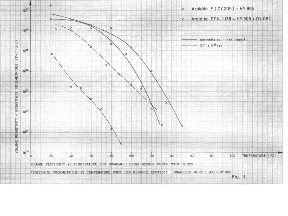
Electrical Properties Changes 2 28/07/201267 Volumetric Resistivity (Ω·cm) 10 10 11 10 12 10 13 10 14 10 15 10 16 10 17 020 40 60 80 100 120 140 160 180 200 Temp. (°C) ○ DGEBA + MDA x EPN + MDA ∆ TGMD +MDA _______ Non irradié _ _ _ _ _ 2.7x10 9 rad T ↑ => ↓ = ~10 16 Ω·cm @RT High mechanical radio-resistance High electrical resistance (mechanical degradation occurs first) Example of low mechanical-resistance system: DGEBA-DBP-TETA = ~10 13 Ω·cm @RT for 6.8x10 8 rad E. Fornasiere
 ○ DGEBA + MDA x EPN + MDA ∆ TGMD +MDA _______ Non irradié _ _ _ _ _ 2.7x10 9 rad T ↑ => ↓ = ~10 16 High mechanical radio-resistance High electrical resistance (mechanical degradation occurs first) Example of low mechanical-resistance system: DGEBA-DBP-TETA = ~10 13 for 6.8x10 8 rad E. Fornasiere.")
68
DGEBA considerations

69
PROPOSALS I Traction test Flexural test Leakage current in air humid Dielectric in air humid Leakage current in air humid after 1 month in water Dielectric in air humid after 1 month in water 0 MGyYY(Y)Y Y 10 MgyY(Y)Y Y 20 MgyYY(Y)Y Y 40 MgyYY(Y)Y Y 50 MGy(Y)Y Y 60 MGyYY(Y)Y Y 70 MGyYY(Y)Y Y Wafer 1 and 2 mm thickness resin and glass fibre
Y Y 10 MgyY(Y)Y Y 20 MgyYY(Y)Y Y 40 MgyYY(Y)Y Y 50 MGy(Y)Y Y 60 MGyYY(Y)Y Y 70 MGyYY(Y)Y Y Wafer 1 and 2 mm thickness resin and glass fibre")
70
PROPOSALS II Shear testLeakage current in air humid Dielectric in air humid Leakage current in air humid after 1 month in water Dielectric in air humid after 1 month in water 0 MGyY(Y)Y Y 10 Mgy(Y)Y Y 20 MgyY(Y)Y Y 40 MgyY(Y)Y Y 50 MGy(Y)Y Y 60 MGyY(Y)Y Y 70 MGyY(Y)Y Y Insulated cables, 2 resins, 3 samples
Y Y 10 Mgy(Y)Y Y 20 MgyY(Y)Y Y 40 MgyY(Y)Y Y 50 MGy(Y)Y Y 60 MGyY(Y)Y Y 70 MGyY(Y)Y Y Insulated cables, 2 resins, 3 samples")
Similar presentations


, M.Magistris (1,2), Th.Otto (2), M.Silari (2) (1) Politecnico di Milano; (2) CERN.>")


>")


 S. Fartoukh,>")

 Collimation WG – IR3 passive absorbers 4 June 2012.>")


