Download presentation
Presentation is loading. Please wait.

1
Welcome This is a document to explains the chosen concept to the animator. This will take you through a 5 section process to provide the necessary details to the animator before starting the animation. The legend on the left will indicate the current status of the document. The big Black coloured number will denote the current section, the Grey color would denote the completed sections, and the Turquoise color would denote the remaining sections. The slides having yellow background (like this one) are the 'Instruction slides' 5 2 1 4 3
 are the Instruction slides")
2
RUBBER ELASTICITY Brief description of the animation (1 or 2 sentences) This animation is about the consequences of the deformation of a network polymer on its entropy and hence its elasticity Related LOs: > Prior Viewing – network polymer, > Future Viewing - Course Name: Level(UG/PG):PG Author(s) :J. Vijay Prasad, Simple Kumar Mentor: Prof. Abhijit P. Deshpande *The contents in this ppt are licensed under Creative Commons Attribution-NonCommercial-ShareAlike 2.5 India license

3
Learning objectives After interacting with this Learning Object, the learner will be able to: Relate the entropy of a polymer chain to its number of conformations. Explain as to why rubber exhibits elasticity. 5 3 2 4 1

4
Master layout or diagram Make a schematic diagram of the concept Explain the animator about the beginning and ending of the process. Draw image big enough for explaining. In the image, identify and label different components of the process/phenomenon. (These are like characters in a film) Illustrate the basic flow of action by using arrows. Use BOLD lines in the diagram (minimum 2pts.) In the slide after that, provide the definitions of ALL the labels used in the diagram You may have multiple master layouts. In this case, number the master layout. (e.g. Master layout 1, 2, 3…) 5 3 2 4 1
 Illustrate the basic flow of action by using arrows. Use BOLD lines in the diagram (minimum 2pts.) In the slide after that, provide the definitions of ALL the labels used in the diagram You may have multiple master layouts. In this case, number the master layout. (e.g. Master layout 1, 2, 3…) ")
5
Master Layout 1 5 3 2 4 1 Entropy of a polymer chain The number of conformations the chain can assume DEPENDS ON

6
Definitions and Keywords 5 3 2 4 1 ENTROPY: Entropy is a measure of disorder or randomness in a system and is also a measure of the tendency of a process. A system tends to proceed in the direction of incresing entropy CONFORMATIONS: The different spatial arrangement of atoms and chemical bonds in a molecule. 1 2

7
Explain the process In this step, use an example to explain the concept. It can be an analogy, a scenario, or an action which explains this concept/process/topic Try to use examples from day-to-day life to make it more clear You have to describe what steps the animator should take to make your concept come alive as a series of moving images. Keep the examples simple to understand, and also to illustrate/animate. 5 3 1 4 2

8
Increase in Entropy tends to Contract a Stretched Chain etc. Only one conformation of maximum length, thus minimum entropy Many conformations of shorter length, thus entropy increases 5 1 4 3 2

9
5 3 1 4 2 To the animator(for the previous slide) Follow the sequence and flow of the previous slide. Images are shown as an example only please redraw them.

10
Stepwise description of process The goal of the document is to provide instructions to an animator who is not a expert. You have to describe what steps the animator should take to make your concept come alive as a moving visualization. Use one slide per step. This will ensure clarity of the explanation. Add a image of the step in the box, and the details in the table below the box. You can use any images for reference, but mention about it's copyright status The animator will have to re-draw / re-create the drawings Add more slides as per the requirement of the animation 5 2 1 4 3

11
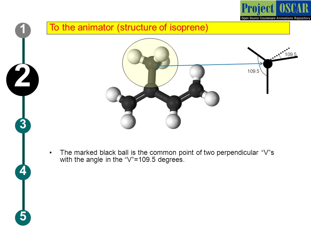
5 3 1 4 2 To the animator (structure of isoprene) The marked black ball is the common point of two perpendicular “V”s with the angle in the “V”=109.5 degrees. 109.5
12
Step 1: T1: Monomer of Natural rubber 5 2 1 4 3 ISOPRENE http://commons.wikimedia.org/wiki/File:Isoprene-3D-balls-B.png

13
Audio Narration (if any) Text to be displayed (DT) Description of the action 5 2 1 4 3 ISOPRENE @bottom center Redraw all the chains. All the marked balls lie on the same plane Do not include the dots in your final image of the picture. The animation should start with the picture and the DT

14
Step 2: T2: Single Poly-isoprene chain 5 2 1 4 3 Natural rubber is a coil of POLY-ISOPRENE chains http://plantsarethestrangestpeople.blogspot.in/2011/09/more-corrections.html

15
Audio Narration (if any) Text to be displayed (DT) Description of the action 5 2 1 4 3 DT-1 Natural rubber is a coil of POLY- ISOPRENE chains @top center DT-2 Single Poly-isoprene chain @bottom left Redraw all the chains. fade out the isoprene picture. The DT-1 should first appear at the centre of the screen and move up. The Above chain shown should appear. The DT-2 should then appear Fade out both DT-1&2 at once

16
Step 3: T3: A Closer Look 5 2 1 4 3

17
Audio Narration (if any) Text to be displayed (DT) Description of the action 5 2 1 4 3 Redraw all the chains. A ring should appear over a part of the chain.

18
Step 4: T4: Polyisoprene main chain with methyl group 5 2 1 4 3 Polymer main chain For the purpose of simplicity we’ll consider only the main chain and the methyl groups

19
Audio Narration (if any) Text to be displayed (DT) Description of the action 5 2 1 4 3 DT-1-Polymer main chain DT-2-For the purpose of simplicity we’ll consider only the main chain and the methyl groups Redraw all the chains. The dt-1 should first appear and fade out after sometime (enough time should be provided for reading) The picture shown should appear to zoom in, out of the ring. The DT and the arrow should appear. Fade out the DT
 The picture shown should appear to zoom in, out of the ring. The DT and the arrow should appear. Fade out the DT.")
20
Step 5: T5: A bond in the chain 5 2 1 4 3

21
Audio Narration (if any) Text to be displayed (DT) Description of the action 5 2 1 4 3 Redraw all the chains. A dotted line should appear on the red line as shown.

22
Step 6: T6: Rotational flips 5 2 1 4 3

23
Audio Narration (if any) Text to be displayed (DT) Description of the action 5 2 1 4 3 Redraw all the chains. The part of the picture on the right hand side should should appear to rotate about the dotted line in the anti- clockwise direction by 180 degrees, (CONTINUOUSLY) upto reaching the above configuration. NOTE: The picture given here is just an approximate idea. The actual image will have slightly different orientations.
 upto reaching the above configuration. NOTE: The picture given here is just an approximate idea. The actual image will have slightly different orientations..")
24
Step 7: T7:Actual structure 5 2 1 4 3 (b) Randomly kinked chain. (a) Planar zig-zag The physics of rubber elasticity, Third Edition-by L.R.G.Treloar, Fig. 3.2
 Planar zig-zag The physics of rubber elasticity, Third Edition-by L.R.G.Treloar, Fig")
25
Audio Narration (if any) Text to be displayed (DT) Description of the action 5 2 1 4 3 Redraw all the chains as in step 2. Start the audio narration The picture (a) should appear when planar zig-zag is read out. the arrow should stretch out from the planar zig zag picture. The picture (b) should appear when randomly kinked is read out. Due to these flips, instead of planar zig-zag form the chain will take up an irregular or randomly kinked form.
 should appear when planar zig-zag is read out. the arrow should stretch out from the planar zig zag picture. The picture (b) should appear when randomly kinked is read out. Due to these flips, instead of planar zig-zag form the chain will take up an irregular or randomly kinked form..")
26
Step 8: T8: 5 2 1 4 3 The actual configuration varies continuously due to thermal agitation Therefore properties can only be specified statistically.

27
Step 9: T9: 5 2 1 4 3 SOME MATHS SKIP Source: Physics of rubber elasticity by L.R.G.Treloar, 3 rd Edition, Chapter-3

28
Audio Narration (if any) Text to be displayed (DT) Description of the action 5 2 1 4 3 Start with the above screen Provide a skip button at the bottom of the screen for every slide upto the star marked slide pointing to the star marked slide Provide next and previous buttons screen for every slide upto the star marked slide
 Text to be displayed (DT) Description of the action Start with the above screen Provide a skip button at the bottom of the screen for every slide upto the star marked slide pointing to the star marked slide Provide next and previous buttons screen for every slide upto the star marked slide")
29
5 2 1 4 3 Probability that the end B of the chain, whose end A is fixed at the origin O, shall be found within a spherical shell of radius r and thickness dr is given by Polymer chain Spherical shell 4πr 2 dr The physics of rubber elasticity, Third Edition-by L.R.G.Treloar, Fig. 3.6

30
5 2 1 4 3 Probability that the end B of the chain, whose end A is fixed at the origin O, shall be found within a spherical shell of radius r and thickness dr is given by (Normal approximation of random walk model) Probability density Volume element b is a constant that depends on chain characteristics The physics of rubber elasticity, Third Edition-by L.R.G.Treloar, eqn 3.9
 Probability density Volume element b is a constant that depends on chain characteristics The physics of rubber elasticity, Third Edition-by L.R.G.Treloar, eqn 3.9")
31
5 2 1 4 3 According to the general principles of statistical thermodynamics, as developed by Boltzmann, the entropy will be proportional to the logarithm of the number of configurations available to the system Number of conformations available to the chain is proportional to the probability

32
5 2 1 4 3 The entropy s of the chain is therefore given by S = ln {( probability density ) x ( volume )} Substitution of the terms yields - where c is an arbitrary constant which includes the volume element dτ (assumed constant) The physics of rubber elasticity, Third Edition-by L.R.G.Treloar, eqn 3.19
 x ( volume )} Substitution of the terms yields - where c is an arbitrary constant which includes the volume element dτ (assumed constant) The physics of rubber elasticity, Third Edition-by L.R.G.Treloar, eqn 3.19")
33
5 2 1 4 3 s = c – kb 2 r 2 STRETCHING A CHAIN INCREASE IN r DECREASE IN ENTROPY NEXT

34
Audio Narration (if any) Text to be displayed (DT) Description of the action 5 2 1 4 3 The screen should go black after the next button is pressed
 Text to be displayed (DT) Description of the action The screen should go black after the next button is pressed")
35
Step 0: Audio Narration (if any) Text to be displayed (@ bottom centre) (DT) Description of the action T0: 5 2 1 4 3 The above text should flash in. Polymer chain configurations at different extensions

36
Step 1: Audio Narration (if any) Text to be displayed (@ bottom centre) (DT) Description of the action T1: AT MAXIMUM EXTENSION 5 2 1 4 3 Only one conformation When a polymer chain is stretched to its maximum length,only one conformation is possible. Hence at this state the entropy of the chain is minimum Redraw all the chains. First the title T1 should appear. Next the chain should fade-in Next the DT should appear at the bottom center.

37
Step 2: 5 2 1 4 3 Audio Narration (if any) Text to be displayed (@ bottom centre) (DT) Description of the action The arrows should move in from the left and right sides and end at the chain ends.
 Text to be displayed bottom centre) (DT) Description of the action The arrows should move in from the left and right sides and end at the chain ends.")
38
Step 3: T3: AT SHORTER LENGTHS 5 2 1 4 3 Many conformations possible But at shorter lengths many conformations are possible Audio Narration (if any) Text to be displayed (@ bottom centre) (DT) Description of the action Title T3 should first appear and remain fixed till step 7.. Arrows should move in with the chain ends and form the above shape. The DT should be displayed at the bottom center and remain fixed till step 7.

39
Step 4: 5 2 1 4 3 T4: AT SHORTER LENGTHS Audio Narration (if any) Text to be displayed (@ bottom centre) (DT) Description of the action Follow the sequence as shown in the steps keeping the ends of the chain fixed till step 7. The transitions should be continuous. A rough idea has been given in section 2.

40
Step 5: 5 2 1 4 3 T5: AT SHORTER LENGTHS Audio Narration (if any) Text to be displayed (@ bottom centre) (DT) Description of the action
 Text to be displayed bottom centre) (DT) Description of the action")
41
Step 6: 5 2 1 4 3 T6: AT SHORTER LENGTHS Audio Narration (if any) Text to be displayed (@ bottom centre) (DT) Description of the action
 Text to be displayed bottom centre) (DT) Description of the action")
42
Step 7: 5 2 1 4 3 T7: AT SHORTER LENGTHS Many conformations possible etc. This leads to an increased randomness in the chain and hence an increase in entropy Audio Narration (if any) Text to be displayed (@ bottom centre) (DT) Description of the action
 Text to be displayed bottom centre) (DT) Description of the action.")
43
Step 8: 5 2 1 4 3 T8: This increase in entropy tends to contract the polymer chain Audio Narration (if any) Text to be displayed (DT) Description of the action Increase in entropy contracts the polymer chain Fade out the polymer chain and display the DT at the center of the screen. Use more bright and attractive colours. Provide next and again buttons that go next to the next or previous Parts of the animations respectively again next

44
Master layout or diagram Make a schematic diagram of the concept Explain the animator about the beginning and ending of the process. Draw image big enough for explaining. In the image, identify and label different components of the process/phenomenon. (These are like characters in a film) Illustrate the basic flow of action by using arrows. Use BOLD lines in the diagram (minimum 2pts.) In the slide after that, provide the definitions of ALL the labels used in the diagram You may have multiple master layouts. In this case, number the master layout. (e.g. Master layout 1, 2, 3…) 5 3 2 4 1
 Illustrate the basic flow of action by using arrows. Use BOLD lines in the diagram (minimum 2pts.) In the slide after that, provide the definitions of ALL the labels used in the diagram You may have multiple master layouts. In this case, number the master layout. (e.g. Master layout 1, 2, 3…) ")
45
Master Layout 3 5 3 2 4 1 RUBBER UNSTRESSED CONDITION STRESSED CONDITION LESS ENTROPY MORE ENTROPY Direction of process

46
Definitions and Keywords 5 3 2 4 1 CROSS-LINKS: Cross-links are bonds that link one polymer chain to the other. VULCANISATION: A chemical process of converting rubber and related polymers into more durable ones by the introduction of cross-links between the polymer chains. 1 2

47
Definitions and Keywords 5 3 2 4 1 AFFINE DEFORMATION: The junction points between chains move on deformation as if they were embedded in an elastic continuum. As a result the components of length of each chain change in the same ratio as the corresponding dimensions of the bulk rubber. 3

48
5 3 4 AFFINE DEFORMATION (in 1 dimension) r2r2 r1r1 l1l1 l2l2 Stretching in the 1 direction of bulk rubber r1r1 r2r2 l1l1 l2l2 Junction point between two chains 2 1 3 Definitions and Keywords
 r2r2 r1r1 l1l1 l2l2 Stretching in the 1 direction of bulk rubber r1r1 r2r2 l1l1 l2l2 Junction point between two chains Definitions and Keywords")
49
5 3 4 2 1 Cross-links Definitions and Keywords CHAIN SEGMENT The part of the polymer chain between successive points of cross-linkage. 4

50
Explain the process In this step, use an example to explain the concept. It can be an analogy, a scenario, or an action which explains this concept/process/topic Try to use examples from day-to-day life to make it more clear You have to describe what steps the animator should take to make your concept come alive as a series of moving images. Keep the examples simple to understand, and also to illustrate/animate. 5 3 1 4 2

51
5 3 1 4 2 Assumptions 1.There is no change of volume on deformation. 2.The deformations are AFFINE in nature. 3.The entropy of the network is the sum of the entropies of the individual chain segments, the latter being given by the formula s = c – kb 2 r 2 Source: Physics of rubber elasticity by L.R.G.Treloar, 3 rd Edition, Chapter-4

52
5 3 1 4 2 Consider an individual chain segment having an end-to end distance represented r 0 = (x 0, y 0, z 0 ), in the unstrained state of the network, and r = (x, y, z) after deformation. Chain segment The physics of rubber elasticity, Third Edition-by L.R.G.Treloar, Fig4.2

53
5 3 1 4 2 By the affine deformation assumption Where λ 1 λ 2 λ 3 are the ratios of the dimensions of the bulk rubber in the x, y and z directions respectively. The physics of rubber elasticity, Third Edition-by L.R.G.Treloar, eqn4.2

54
5 3 1 4 2 By the constant volume assumption Where λ 1 λ 2 λ 3 are the ratios of the dimensions of the bulk rubber in the x, y and z directions respectively. The physics of rubber elasticity, Third Edition-by L.R.G.Treloar, eqn4.1

55
5 3 1 4 2 Entropy of the chain in the original state Entropy of the same chain in the strained state Contribution to the total entropy of deformation for the network due to this chain segment

56
5 3 1 4 2 The total entropy of deformation Since the directions of the chain vectors r 0 in the unstrained state are entirely random, there will be no preference for the x, y, or z directions and we have an assembly of N chain segments per unit volume hence Mean squared length for a chain segment

57
5 3 1 4 2 Substituting the above relations in the equation for ΔS, we get Source: Physics of rubber elasticity by L.R.G.Treloar, 3 rd Edition, eqn-4.8

58
During extension there is a decrease in entropy Stretching 5 3 1 4 2 https://webspace.yale.edu/chem125/index.html#1stquarter https://webspace.yale.edu/chem125/index.html#1stquarter

59
To the animator(for the previous slide) Follow the sequence and flow of the previous slide. Images are shown as an example only please redraw them. 5 3 1 4 2

60
Stepwise description of process The goal of the document is to provide instructions to an animator who is not a expert. You have to describe what steps the animator should take to make your concept come alive as a moving visualization. Use one slide per step. This will ensure clarity of the explanation. Add a image of the step in the box, and the details in the table below the box. You can use any images for reference, but mention about it's copyright status The animator will have to re-draw / re-create the drawings Add more slides as per the requirement of the animation 5 2 1 4 3

61
5 1 4 2 3 Step 1: T1:Vulcanised Rubber Source: www.officer.com/product/10053604/ballistic-rubber-range-products-ballistic-rubber-range-block

62
5 1 4 2 3 Audio Narration (if any) Text to be displayed (@ bottom centre) (DT) Description of the action Start the animation with the picture shown.
 Text to be displayed bottom centre) (DT) Description of the action Start the animation with the picture shown.")
63
5 1 4 2 3 Step 2: T2: looking closely

64
5 1 4 2 3 Audio Narration (if any) Text to be displayed (@ bottom centre) (DT) Description of the action Start the animation with the picture shown. A ring should appear over a part of the picture as shown.

65
5 1 4 2 3 Step 3: T3: Rubber- a tangled coil

66
5 1 4 2 3 Step 4: T4: Rubber- a tangled coil (a closer look)
")
67
5 1 4 2 3 Audio Narration (if any) Text to be displayed (@ bottom centre) (DT) Description of the action Start the animation with the picture shown. Put attractive colors for the text. The picture shown should appear to zoom in, out of the ring.

68
5 1 4 2 3 Step 5: T5: Unstretched state A B

69
5 1 4 2 3 A B 3 d block Step 5: T5: Unstretched state

70
5 1 4 2 3 A B Isolating chain to graph

71
5 1 4 2 3 0 r = (x 0, y 0, z 0 ) x y z
 x y z")
72
5 1 4 2 3 elongation

73
5 1 4 2 3 IMPORTANT INSTRUCTIONS TO THE ANIMATOR Step1 Isolate the part of the green chain between the triangle points to a 3-d graph( i.e fade out the entire image except the part of the chain and fade in a coordinate system) with one end at the origin. Develop a method to get the (x 0, y 0, z 0 ) of the other end Report the coordinates Instructions The block should elongate along the shown (x direction). Keep about 4-6 chains between the two block A and B ( Ensure that the chains are clearly distinguishable and use a different colour for each chain. Make the chains relatively more wavy for the initial unelongated block. The end points of chain must be fixed to A and B @ the same position even after elongation The crosslinks (red lines) must be of constant length at all times and must have their end points fixed on any two chains. During Elongation The ends of the chains on A and B must be fixed. The ends of the red links must be fixed the respective chains. The length of chains must be fixed. The chains are allowed to have any wavy configuration but ensure that the red links and the triangular points are clearly visible. After final Elongation Isolate the part of the green chain between the triangle points to a 3-d graph ( i.e fade out the entire image except the part of the chain and fade in a coordinate system) with one end at the origin. Develop a method to get the (x, y, z) of the other end. Report the coordinates. Ensure that the quantity (x/x 0 ) 2 +(y/y 0 ) 2 +(z/z 0 ) 2 > 3 Else manipulate the waviness of the chain to satisfy the above condition The elongation part has been explained step wise on a 2-d scale. Please make it 3-d
 of the other end Report the coordinates Instructions The block should elongate along the shown (x direction). Keep about 4-6 chains between the two block A and B ( Ensure that the chains are clearly distinguishable and use a different colour for each chain. Make the chains relatively more wavy for the initial unelongated block. The end points of chain must be fixed to A and the same position even after elongation The crosslinks (red lines) must be of constant length at all times and must have their end points fixed on any two chains. During Elongation The ends of the chains on A and B must be fixed. The ends of the red links must be fixed the respective chains. The length of chains must be fixed. The chains are allowed to have any wavy configuration but ensure that the red links and the triangular points are clearly visible. After final Elongation Isolate the part of the green chain between the triangle points to a 3-d graph ( i.e fade out the entire image except the part of the chain and fade in a coordinate system) with one end at the origin. Develop a method to get the (x, y, z) of the other end. Report the coordinates. Ensure that the quantity (x/x 0 ) 2 +(y/y 0 ) 2 +(z/z 0 ) 2 > 3 Else manipulate the waviness of the chain to satisfy the above condition The elongation part has been explained step wise on a 2-d scale. Please make it 3-d.")
74
5 1 4 2 3 Audio Narration (if any) Text to be displayed (@ bottom centre) (DT) Description of the action NOTE: The network of chains shown from now on, are a 2-d view. Please redraw a 3-d version of the image and use that instead. Redraw the figure with all the chains and the links (yellow lines) in-between such that when you move individual chains the links also move relatively First the figure should fade-in at the center Next the DT-1 should appear at the bottom center and fade out after a few seconds. DT-2 should then appear and fade away. Do not include the text A,B and 3d block in the final animation. DT-1: Less orderness DT-2: More Entropy
 in-between such that when you move individual chains the links also move relatively First the figure should fade-in at the center Next the DT-1 should appear at the bottom center and fade out after a few seconds. DT-2 should then appear and fade away. Do not include the text A,B and 3d block in the final animation. DT-1: Less orderness DT-2: More Entropy.")
75
5 1 4 2 3 Step 6: T6: Initial condition 0 r = (x 0, y 0, z 0 ) x y z
 x y z")
76
5 1 4 2 3 Step 7: T7: While Stretching

77
5 1 4 2 3 Audio Narration (if any) Text to be displayed (@ bottom centre) (DT) Description of the action Redraw all figures as explained in step 2 First an arrow should appear to move out from the figure as shown. <none.

78
5 1 4 2 3 Step 8: T8: While stretching

79
5 1 4 2 3 Audio Narration (if any) Text to be displayed (@ bottom centre) (DT) Description of the action Redraw all the figures as described The distance between two yellow blocks should appear to increase with the right block fixed. Take care that the transition happens continuously and the links remain relatively fixed between chains.

80
5 1 4 2 3 Step 9: T9: While stretching

81
5 1 4 2 3 Audio Narration (if any) Text to be displayed (@ bottom centre) (DT) Description of the action Redraw all the figures as described The distance between two yellow blocks should appear to increase with the right block fixed. Take care that the transition happens continuously and the links remain relatively fixed between their respective chains. The DT should be displayed as the transition happens, and should remain fixed at the bottom center. Decreasing randomness

82
5 1 4 2 3 Step 10: T10: While stretching

83
5 1 4 2 3 Audio Narration (if any) Text to be displayed (@ bottom centre) (DT) Description of the action Decreasing randomness Redraw all the figures as described The distance between two yellow blocks should appear to increase with the right block fixed. Take care that the transition happens continuously and the links remain relatively fixed between chains. The DT should be displayed as the transition happens at the bottom center.

84
5 1 4 2 3 Step 11: T11:While stretching

85
5 1 4 2 3 Step 12: T12: new coordinates 0 r = (x, y, z) x y z
 x y z")
86
5 1 4 2 3 Audio Narration (if any) Text to be displayed (@ bottom centre) (DT) Description of the action Redraw all the figures as described Report x y z within the brackets.
 Text to be displayed bottom centre) (DT) Description of the action Redraw all the figures as described Report x y z within the brackets.")
87
5 1 4 2 3 Step 13: From the formula we derived We can See that ΔS < 0

88
5 1 4 2 3 Audio Narration (if any) Text to be displayed (@ bottom centre) (DT) Description of the action The screen should first go blank The text as shown should appear-in.
 Text to be displayed bottom centre) (DT) Description of the action The screen should first go blank The text as shown should appear-in.")
89
5 1 4 2 3 Step 14: T14: Contraction

90
5 1 4 2 3 Audio Narration (if any) Text to be displayed (@ bottom centre) (DT) Description of the action The figure shown should fade in Follow the steps 6 to 3 (reverse direction) Keep the right block fixed and the distance between the two blocks should keep on decreasing upto step 3 Please take care that the transitions between images occur continuously with the yellow links moving relatively Change the title to “Contraction”.
 Text to be displayed bottom centre) (DT) Description of the action The figure shown should fade in Follow the steps 6 to 3 (reverse direction) Keep the right block fixed and the distance between the two blocks should keep on decreasing upto step 3 Please take care that the transitions between images occur continuously with the yellow links moving relatively Change the title to Contraction .")
91
5 1 4 2 3 Step 15: again next

92
5 1 4 2 3 Audio Narration (if any) Text to be displayed (@ bottom centre) (DT) Description of the action A continuous transition should happen between step 3 to step 1 as described previously. A rough idea has been given in the explanation section. Provide a next button as shown, that on clicking goes to the next part. Provide an again button as shown, that on clicking goes to the previous part of the animation. Increase in disorderness or randomness

93
Animation design Please see the design template provided in the next slide. This is a sample template, and you are free to change as per your design requirements. Try and rename the tabs / buttons / sections / subsections as shown in the template. Use ‘callouts’ as shown above to explain the source of content. Ex: If the call out is placed at the Tab 01, and you want the content to be taken from slide 3 of this presentation, then place this callout on the Tab 01, and write ‘Slide 3’ inside the callout. Slide 3 5 2 1 3 4

94
DEFORMATION OF A NETWORK Animation area Instructions/ Working area Credits Name of the section/stage Interactivity area Equations of Chain entropy Chain Entropy Introduction to Network polymer Equations of Network entropy QuestionnaireSummary Rubber Stretching Chain Entropy- Introduction Slide 5-6 & 12-26 Deformation of a network Slide 27-34 slide 35- 43 slide 45- 49 slide 51- 57 slide 61- 92 Slide 101 Slide 105

95
Interactivity and Boundary limits In this section, you will add the ‘Interactivity’ options to the animation. Use the template in the next slide to give the details. Insert the image of the step/s (explained earlier in the Section 3) in the box, and provide the details in the table below. The details of Interactivity could be: Types: Drop down, Slider bar, Data inputs etc. Options: Select one, Multiple selections etc Boundary Limits: Values of the parameters, which won’t show results after a particular point Results: Explain the effect of the interaction in this column Add more slides if necessary 4 2 1 3 5
 in the box, and provide the details in the table below. The details of Interactivity could be: Types: Drop down, Slider bar, Data inputs etc. Options: Select one, Multiple selections etc Boundary Limits: Values of the parameters, which won’t show results after a particular point Results: Explain the effect of the interaction in this column Add more slides if necessary")
96
Instructions for the animator Instruction to the learner Results and Output Boundary limits Interactivity type Interactivity option 1: Step No: 1 4 2 1 3 5 TOTAL ENTROPY Redraw all the figures. Add 3d effects to the rubber(grey) block. The user should be able to click and drag to stretch the block to the left The transition during stretching should be continuous. The red button should light up when the cursor moves over it. The red button(for click and drag) should move along with the block while stretching. MAXIMUM ENTROPY Minimum and maximum length of the block as shown. The minimum length should correspond to the top position of the yellow circle and the maximum to the bottom Stretch the rubber block by dragging the red button Quantitative property change
 block. The user should be able to click and drag to stretch the block to the left The transition during stretching should be continuous. The red button should light up when the cursor moves over it. The red button(for click and drag) should move along with the block while stretching. MAXIMUM ENTROPY Minimum and maximum length of the block as shown. The minimum length should correspond to the top position of the yellow circle and the maximum to the bottom Stretch the rubber block by dragging the red button Quantitative property change.")
97
Instructions for the animator Instruction to the learner Results and Output Boundary limits Interactivity type Interactivity option 1: Step No: 2 4 2 1 3 5 TOTAL ENTROPY Keep the position of the right edge of the block fixed. While stretching the area of the block should be kept constant. Synchronize the vertical downward movement of the yellow circle on the scale (to the right of the screen) with the stretching of the block to the left. DECREASING ENTROPY
 with the stretching of the block to the left. DECREASING ENTROPY.")
98
Instructions for the animator Instruction to the learner Results and Output Boundary limits Interactivity type Interactivity option 1: Step No: 3 4 2 1 3 5 TOTAL ENTROPY Display text- MAXIMUM ENTROPY at the beginning of the interactivity Display text- DECREASING ENTROPY while the stretching happens. DECREASING ENTROPY

99
Instructions for the animator Instruction to the learner Results and Output Boundary limits Interactivity type Interactivity option 1: Step No: 4 4 2 1 3 5 TOTAL ENTROPY MAXIMUM ENTROPY When the click is terminated the block should quickly compress back to the original state and the yellow circle should move up synchronized with the compress of the block. Display text- INCREASING ENTROPY while the compression happens. Display text- MAXIMUM ENTROPY at the end The learner gets a clear picture of the variation of entropy with stretching of rubber.

100
Self- Assessment Questionnaire for Learners Please provide a set of questions that a user can answer based on the LO. They can be of the following types: – These questions should be 5 in number and can be of objective type (like MCQ, Match the columns, Yes or No, Sequencing, Odd One Out). – The questions can also be open-ended. The user would be asked to think about the question. The author is requested to provide hints if possible, but a full answer is not necessary. – One can include questions, for which the user will need to interact with the LO (with certain parameters) in order to answer it. – It is better to avoid questions based purely on recall. APPENDIX 1
. – The questions can also be open-ended. The user would be asked to think about the question. The author is requested to provide hints if possible, but a full answer is not necessary. – One can include questions, for which the user will need to interact with the LO (with certain parameters) in order to answer it. – It is better to avoid questions based purely on recall. APPENDIX 1.")
101
Questionnaire: 1.The monomer of natural rubber is __________. 2.A polymer chain in state A has an end to end distance ‘r’ and in state B has an end to end distance of ‘R’ with r<R. What can say about the entropy of the chain s A in state A and s B in state B. 3.One of the ways to produce a network polymer is by vulcanization. TRUE or FALSE :- Vulcanization is done to weaken natural rubber. 4.What is affine deformation? 5.Stretching a rubber band leads to ________ in its entropy. APPENDIX 1 a) s A s B c)s A =s B
 s A s B c)s A =s B.")
102
Links for further reading In the next slide, provide some reference reading material for the users. It could be books, reference publications, or website URLs. APPENDIX 2

103
Links for further reading Reference websites: http://en.wikipedia.org/wiki/Natural_rubber http://en.wikipedia.org/wiki/Natural_rubber https://webspace.yale.edu/chem125/index.html#1stquarter https://webspace.yale.edu/chem125/index.html#1stquarter Books: The physics of rubber elasticity, Third Edition-by L.R.G.Treloar, chapter 3 &4 Research papers: On a Possible Model of an Anisotropic Rubber Network-By D. Neubert Original image source: https://webspace.yale.edu/chem125/index.html#1stquarter https://webspace.yale.edu/chem125/index.html#1stquarter www.officer.com/product/10053604/ballistic-rubber-range-products- ballistic-rubber-range-block www.officer.com/product/10053604/ballistic-rubber-range-products- ballistic-rubber-range-block http://commons.wikimedia.org/wiki/File:Isoprene-3D-balls-B.png http://commons.wikimedia.org/wiki/File:Isoprene-3D-balls-B.png APPENDIX 2

104
Summary Please provide points to remember to understand the concept/ key terms of the animation, in the next slide. The summary will help the user in the quick review of the concept. APPENDIX 3

105
Summary APPENDIX 3 The actual configuration of a polymer chain varies continuously due to thermal agitation and can only be determined statistically. The entropy of a polymer chain is proportional to the number of configurations a chain can assume and hence - Thus entropy of a chain decreases with increase in the distance ‘r’ between its end points In affine deformation the junction points between chains move as if they were embedded in an elastic continuum. For small deformations of vulcanised rubber the affine deformation assumption holds. The total entropy of a collection of interlinked chains is equal to the sum of the individual entropies of the chain segments and hence – The entropy of rubber decreases under stress due to deformation and hence contracts back when stress is removed increasing its entropy. Thus rubber shows elasticity.

Similar presentations


