Download presentation
Presentation is loading. Please wait.

1
Fundamentals of Electric Circuits Chapter 7
Copyright © The McGraw-Hill Companies, Inc. Permission required for reproduction or display.

2
Overview This chapter examines RC and LC circuits’ reaction to switched sources. The circuits are referred to as first order circuits. Three special functions, the unit step, unit impulse, and unit ramp function are also introduced. Both source free and switched sources are examined.

3
First Order Circuits A first order circuit is characterized by a first order differential equation. There are two types of first order circuits: Resistive capacitive, called RC Resistive inductive, called RL There are also two ways to excite the circuits: Initial conditions Independent sources

4
Source Free RC Circuit A source free RC circuit occurs when its dc source is suddenly disconnected. The energy stored in the capacitor is released to the resistors. Consider a series combination of a resistor and a initially charged capacitor as shown:

5
Source Free RC Circuit Since the capacitor was initially charged, we can assume at t=0 the initial voltages is: Applying KCL at the top node: Or This is a first order differential equation.

6
Source Free RC Circuit Rearranging the equation and solving both sides yields: Where A is the integration constant Taking powers of e produces With the initial conditions:

7
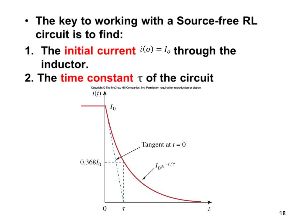
Natural Response The result shows that the voltage response of the RC circuit is an exponential decay of the initial voltage. Since this is the response of the circuit without any external applied voltage or current, the response is called the natural response.

8
Time Constant The speed at which the voltage decays can be characterized by how long it takes the voltage to drop to 1/e of the initial voltage. This is called the time constant and is represented by . By selecting 1/e as the reference voltage: The voltage can thus be expressed as:

9
Time Constant II After five time constants the voltage on the capacitor is less than one percent. After five time constants a capacitor is considered to be either fully discharged or charged A circuit with a small time constant has a fast response and vice versa.

10
RC Discharge With the voltage known, we can find the current:
The power dissipated in the resistor is: The energy absorbed by the resistor is:

11
Source Free RC Circuit Summary
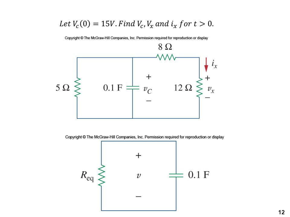
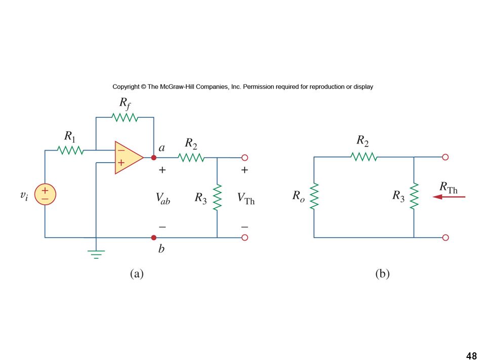
The key to working with this type of situation is: Start with the initial voltage across the capacitor and the time constant. With these two items, the voltage as a function of time can be known. From the voltage, the current can be known by using the resistance and Ohm’s law. The resistance of the circuit is often the Thevenin equivalent resistance.

15
Source Free RL Circuit Now let us consider the series connection of a resistor and inductor. In this case, the value of interest is the current through the inductor. Since the current cannot change instantaneously, we can determine its value as a function of time. Once again, we will start with an initial current passing through the inductor.

16
Source Free RL Circuit We will take the initial current to be:
Applying KVL around the loop: Or:

17
Source Free RL Circuit After integration:
Once again, the natural response is an exponentially decaying current. The time constant in this case is: The same principles as the RC circuit apply here.

23
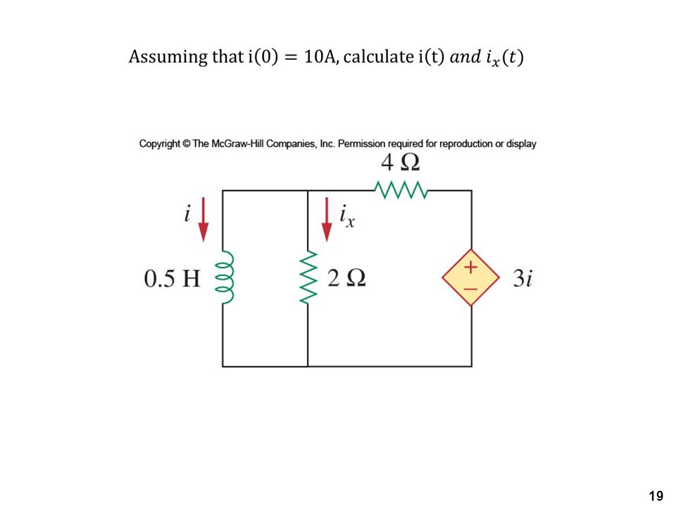
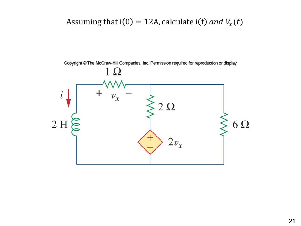
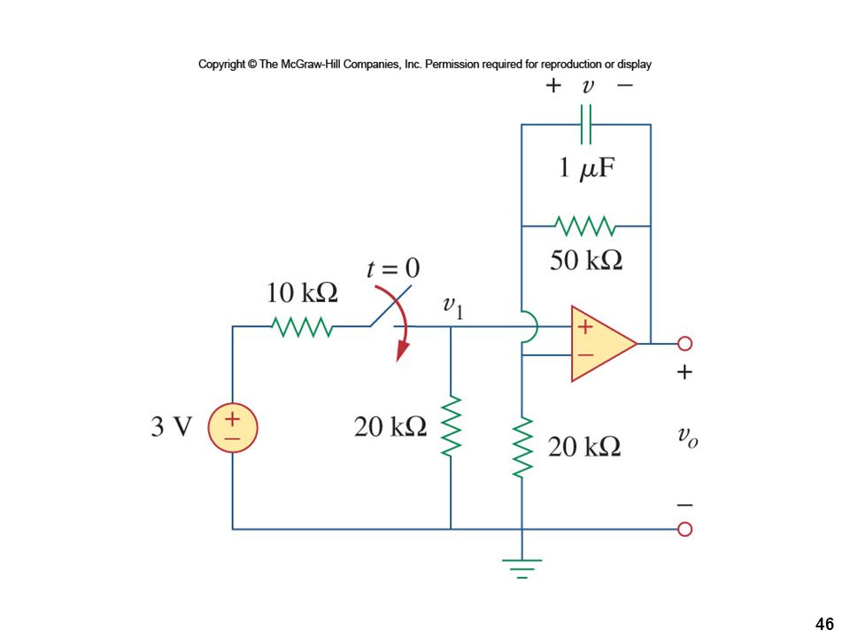
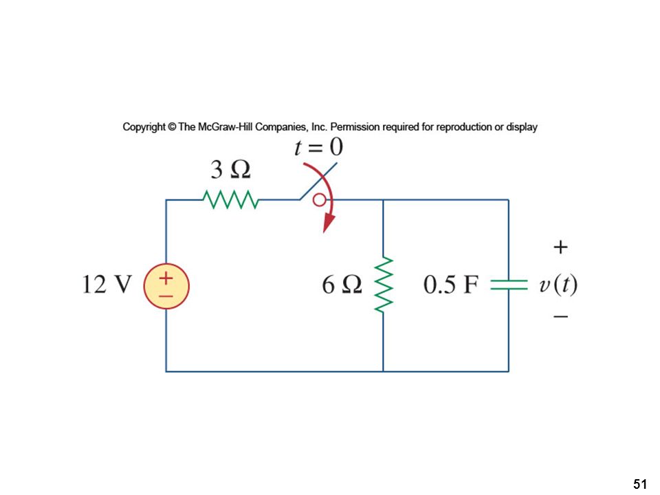
Practice

24
Singularity Functions
Before we consider the response of a circuit to an external voltage, we need to cover some important mathematical functions. Singularity functions serve as good approximations to switching on or off a voltage. The three most common singularity functions are the unit step, unit impulse, and unit ramp.

25
The Unit Step Mathematically, the unit step is expressed as:
The switching time may be shifted to t=t0 by: Note that this results in a delay in the switch. The unit step function is written as u(t)
")
26
Equivalent Circuit The unit step function has an equivalent circuit to represent when it is used to switch on a source. The equivalent circuits for a voltage and current source are shown.

27
The Unit Impulse Function
The derivative of the unit step function is the unit impulse function. This is expressed as: Voltages of this form can occur during switching operations.

28
The Unit Ramp Function Integration of the unit step function results in the unit ramp function:

30
Step Response of RC Circuit

31
Step Response of RC Circuit
We assume an initial voltage of V0 on the capacitor. Applying KCL: For t >0 this becomes: Integrating both sides and introducing initial conditions finally yields:

32
Step Response of RC Circuit
This is known as the complete response, or total response. We can consider the response to be broken into two separate responses: The natural response of the capacitor or inductor due to the energy stored in it. The second part is the forced response

33
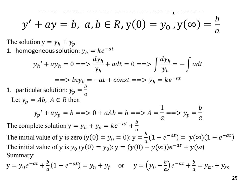
Forced Response The complete response can be written as:
Where the nature response is: And the forced response is: Note that the eventual response of the circuit is to reach Vs after the natural response decays to zero.

34
Another Perspective Another way to look at the response is to break it up into the transient response and the steady state response: Where the transient state is: And the steady state is:

35
Step Response of RL Circuit
Now we can look at the step response of a RL circuit. We will use the transient and steady state response approach. We know that the transient response will be an exponential:

36
Step Response of RL Circuit
After a sufficiently long time, the current will reach he steady state: This yields an overall response of: To determine the value of A we need to keep in mind that the current cannot change instantaneously.

37
Step Response of RL Circuit
Thus we can use the t=0 time to establish A The complete response of the circuit is thus: Without an initial current, the circuit response is shown here.

38
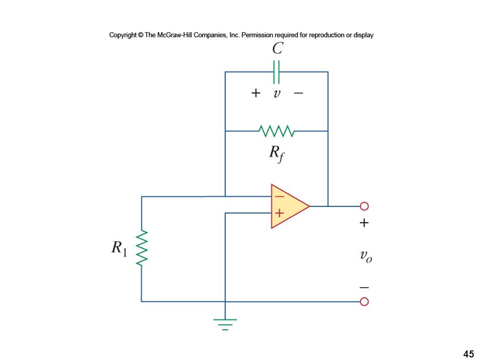
Application: Delay Circuit
The RC circuit can be used to delay the turn on of a connected device. For example, a neon lamp which only triggers when a voltage exceeds a specific value can be delayed using such a circuit.

39
Delay Circuit II When the switch is closed, the capacitor charges.
The voltage will rise at a rate determined by: Once the voltage reaches 70 volts, the lamp triggers. Once on, the lamp has low resistance and discharges the capacitor. This shuts off the capacitor and starts the cycle over again.

40
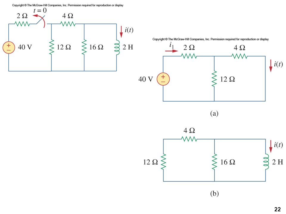
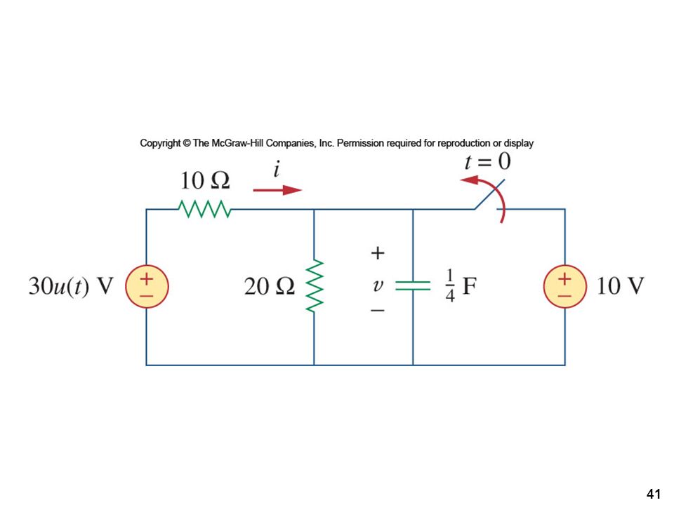
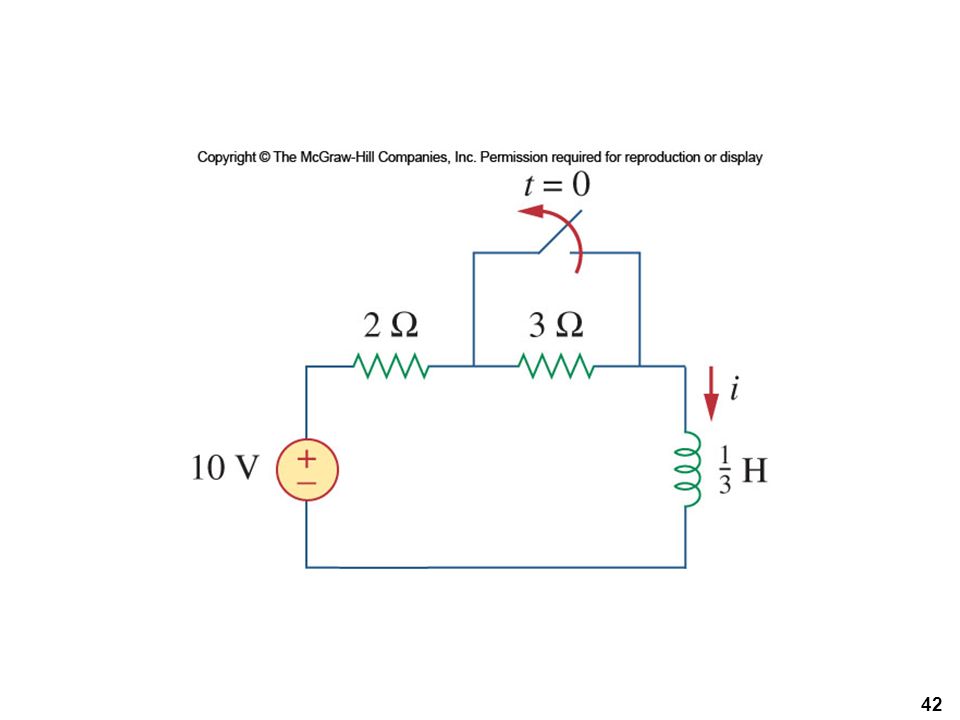
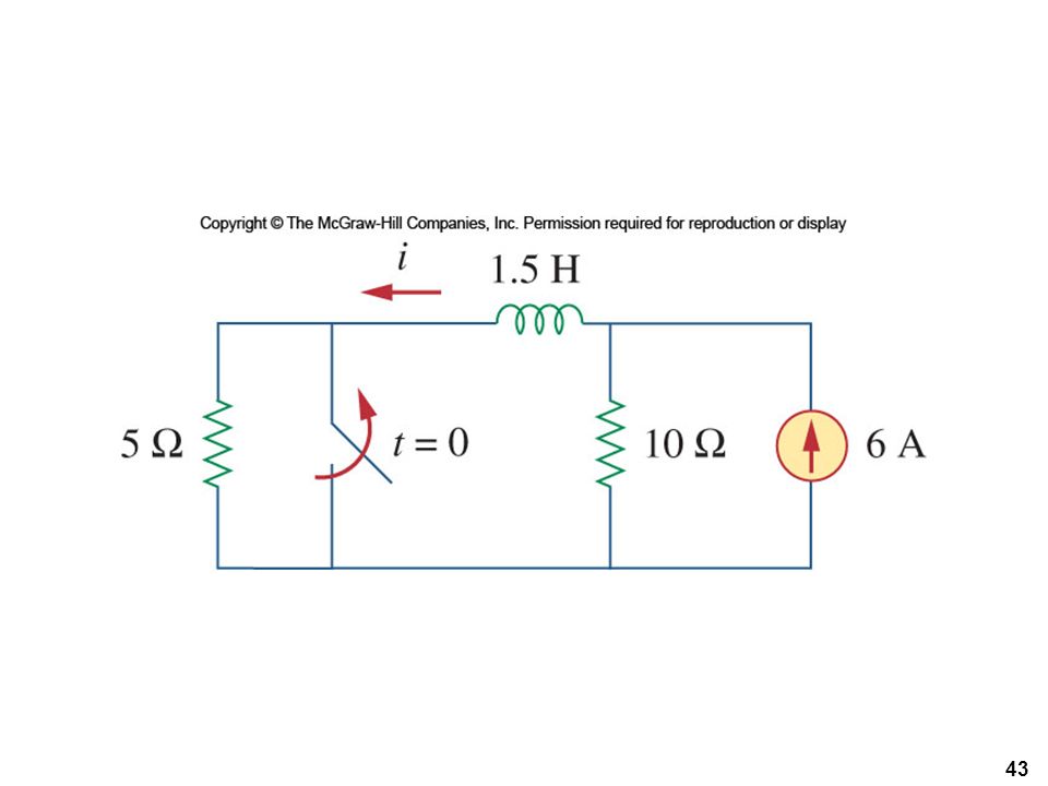
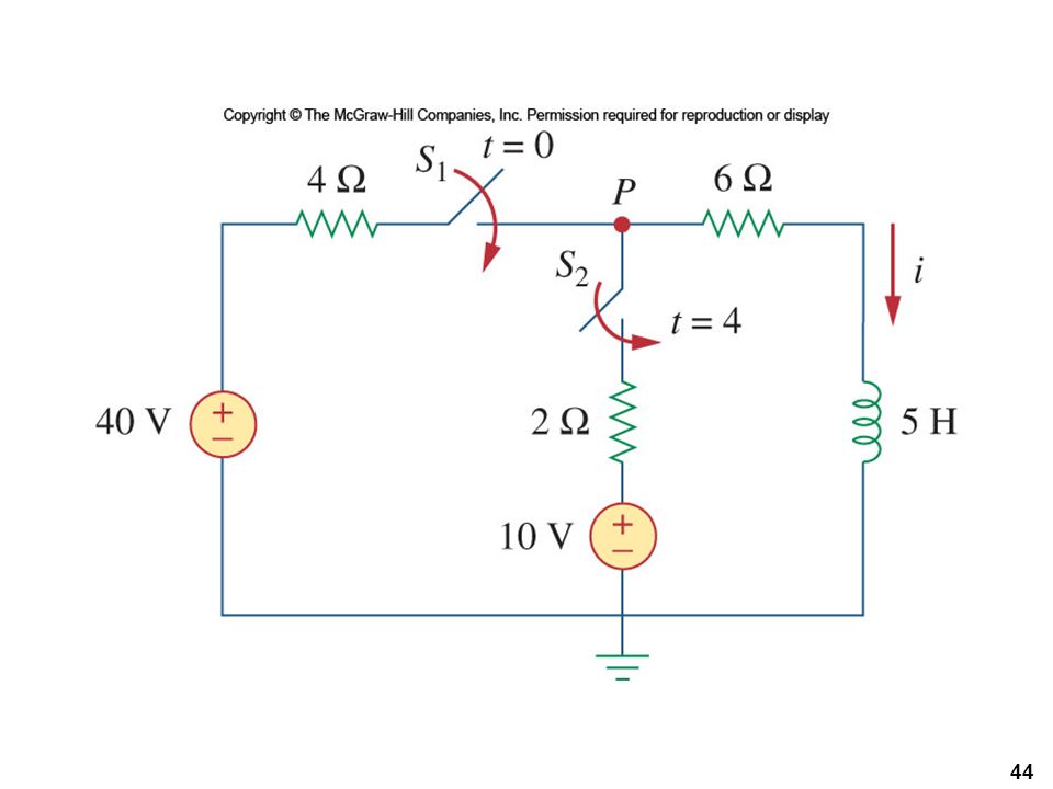
Practice

Similar presentations


>")


 Circuits AP Physics C. RC Circuit – Initial Conditions An RC circuit is one where you have a capacitor and resistor in the same.>")
 Chapter (2) AC- circuits Capacitors and transient current 1.>")
 Circuits>")

