Download presentation
Presentation is loading. Please wait.

1
1. Strengthening and recrystallization of plastically deformed metals
1. Strengthening and recrystallization of plastically deformed metals. 2. Material selection according to the mechanical properties Lecture 6

2
Why study strengthening mechanisms?
We can tailor the mechanical properties of an engineering material by choosing between strength and toughness

3
Plastic Deformation Plastic deformation is permanent, and strength and hardness are measures of a material’s resistance to this deformation. On a microscopic scale, plastic deformation corresponds to the net movement of large numbers of atoms in response to an applied stress. In crystalline solids, plastic deformation most often involves the motion of dislocations The ability of a metal to plastically deform depends on the ability of dislocations to move 2. … During this process, interatomic bonds must be ruptured and then reformed

4
Dislocation Motion Cubic & hexagonal metals - plastic deformation by plastic shear or slip where one plane of atoms slides over adjacent plane by defect motion (dislocations). So we saw that above the yield stress plastic deformation occurs. But how? In a perfect single crystal for this to occur every bond connecting two planes would have to break at once! Large energy requirement Now rather than entire plane of bonds needing to be broken at once, only the bonds along dislocation line are broken at once. If dislocations don't move, deformation doesn't occur!
. So we saw that above the yield stress plastic deformation occurs. But how In a perfect single crystal for this to occur every bond connecting two planes would have to break at once! Large energy requirement. Now rather than entire plane of bonds needing to be broken at once, only the bonds along dislocation line are broken at once. If dislocations don t move, deformation doesn t occur!")
5
Dislocation Motion The process by which plastic deformation is produced by dislocation motion is termed slip Dislocation moves along slip plane in slip direction perpendicular to dislocation line Edge dislocation … the crystallographic plane along which the dislocation line traverses is the slip plane, Ordinarily there is a preferred plane, and in that plane there are specific directions along which dislocation motion occurs. This plane is called the slip plane; it follows that the direction of movement is called the slip direction. This combination of the slip plane and the slip direction is termed the slip system. Burgers vector (b) represents the magnitude and direction of the distortion of dislocation in a crystal lattice Screw dislocation
 represents the magnitude and direction of the distortion of dislocation in a crystal lattice. Screw dislocation.")
6
Strengthening of Metals
Good industrial alloys -> high strengths yet some ductility and toughness Since hardness and strength are related to the ease with which plastic deformation can be made to occur, by reducing the mobility of dislocations, the mechanical strength may be enhanced In contrast, the more unconstrained the dislocation motion, the greater is the facility with which a metal may deform, and the softer and weaker it becomes Restricting or hindering dislocation motion renders a material harder and stronger … ordinarily, ductility is sacrificed when an alloy is strengthened … (both yield and tensile) … that is, greater mechanical forces will be required to initiate plastic deformation . All strengthening techniques rely on this simple principle: …
 … that is, greater mechanical forces will be required to initiate plastic deformation. . All strengthening techniques rely on this simple principle: …")
7
Strengthening Methods
grain size reduction, solid-solution alloying, precipitation hardening/strengthening strain hardening/strengthening

8
Strategies for Strengthening: 1: Reduce Grain Size
• Grain boundaries are barriers to slip. • Barrier "strength" increases with Increasing angle of misorientation. • Smaller grain size: more barriers to slip. • Hall-Petch Equation: Figure -> Adjacent grains normally have different crystallographic orientations and, of course, a common grain boundary. During plastic deformation, slip or dislocation motion must take place across this common boundary—say, from grain A to grain B 3. Small-angle grain boundaries are not effective in interfering with the slip process because of the slight crystallographic misalignment across the boundary. On the other hand, twin boundaries will effectively block slip and increase the strength of the material Before equation -> A fine-grained material (one that has small grains) is harder and stronger than one that is coarse grained, since the former has a greater total grain boundary area to impede dislocation motion Equation -> It should also be mentioned that grain size reduction improves not only strength, but also the toughness of many alloys d is the average grain diameter. σo and ky are constants for a particular material
 is harder and stronger than one that is coarse grained, since the former has a greater total grain boundary area to impede dislocation motion. Equation -> It should also be mentioned that grain size reduction improves not only strength, but also the toughness of many alloys. d is the average grain diameter. σo and ky are constants for a particular material.")
9
Dependence of Yield Strength on Grain Size
Grain size may be regulated by the rate of solidification from the liquid phase, and also by plastic deformation followed by an appropriate heat treatment The influence of grain size on the yield strength of a 70 Cu–30 Zn brass alloy

10
Strategies for Strengthening: 2: Solid Solution Strengthening
• Impurity atoms distort the lattice & generate stress. • Stress can produce a barrier to dislocation motion. • Smaller substitutional impurity A B • Larger substitutional impurity C D Impurity can either be substitutional or interstitial. Alloys are stronger than pure metals because impurity atoms that go into solid solution ordinarily impose lattice strains on the surrounding host atoms. Lattice strain field interactions between dislocations and these impurity atoms result, and, consequently, dislocation movement is restricted.

11
Stress Concentration at Dislocations

12
SSS - Impurity Atoms An impurity atom that is smaller than a host atom for which it substitutes exerts tensile strains on the surrounding crystal lattice A larger substitutional atom imposes compressive strains in its vicinity

13
SSS – Effects of Impurity Atoms
The resistance to slip is greater when impurity atoms are present because the overall lattice strain must increase if a dislocation is moved away from them. The same lattice strain interactions will exist between impurity atoms and dislocations that are in motion during plastic deformation. Thus, a greater applied stress is necessary to first initiate and then continue plastic deformation for solid-solution alloys, as opposed to pure metals 2. … (Figures on previous slide) … 3. … This is evidenced by the enhancement of strength and hardness
 … 3. … This is evidenced by the enhancement of strength and hardness.")
14
SSS – Strength and Ductility
High-purity metals are almost always softer and weaker than alloys composed of the same base metal. Increasing the concentration of the impurity results in an attendant increase in tensile and yield strengths Variation with nickel content of (a) tensile strength, (b) yield strength, and (c) ductility (%EL) for copper–nickel alloys, showing strengthening.
 tensile. strength, (b) yield strength, and (c) ductility (%EL) for copper–nickel alloys, showing strengthening.")
15
Strategies for Strengthening: 3: Precipitation Strengthening
Precipitation strengthening, also called age hardening, is a heat treatment technique used to increase the yield strength of malleable materials. It relies on changes in solid solubility with temperature to produce fine particles of an impurity phase, which impede the movement of dislocations, or defects in a crystal's lattice. Precipitation in solids can produce many different sizes of particles, which have different properties. Alloys must be kept at elevated temperature for hours to allow precipitation to take place. This time delay is called aging … including most structural alloys of aluminum, magnesium, nickel and titanium, and some stainless steels. Precipitation heat treating involves the addition of impurity particles to increase a material's strength … Since dislocations are often the dominant carriers of plasticity, this serves to harden the material. Just as the formation of ice in air can produce clouds, snow, or hail, depending upon the thermal history of a given portion of the atmosphere …

16
Strategies for Strengthening: 3: Precipitation Strengthening
• Hard precipitates are difficult to shear. Ex: Ceramics in metals (SiC in Iron or Aluminum). Side View precipitate Top View Slipped part of slip plane Unslipped part of slip plane S spacing Large shear stress needed to move dislocation toward precipitate and shear it. Dislocation “advances” but precipitates act as Fig. 2. -> Dislocation moving in upward direction (restrained by precipitates) “pinning” sites with spacing S . • Result:
. Side View. precipitate. Top View. Slipped part of slip plane. Unslipped part of slip plane. S. spacing. Large shear stress needed. to move dislocation toward. precipitate and shear it. Dislocation. advances but. precipitates act as. Fig. 2. -> Dislocation moving in upward direction (restrained by precipitates) pinning sites with. spacing. S. . • Result:")
17
Application: Precipitation Strengthening
• Internal wing structure on Boeing 767 • Aluminum is strengthened with precipitates formed by alloying. 1.5mm Common Aluminum alloy precipitate compounds -> Al2Cu; Al3Sc (Sc-Scandium); Al2CuMg
; Al2CuMg.")
18
Strategies for Strengthening: 4: Strain-Hardening
• Room temperature deformation. • Common forming operations change the cross sectional area: -Forging A o d force die blank -Rolling roll A o d -Drawing tensile force A o d die -Extrusion ram billet container force die holder die A o d extrusion %CW -> percentage cold work

19
Dislocations During Cold Work
• Ti alloy after cold working: 0.9 mm • Dislocations entangle with one another during cold work. • Dislocation motion becomes more difficult.

20
Result of Cold Work Dislocation density =
total dislocation length unit volume Dislocation density = Carefully grown single crystal 103 mm-2 Deforming sample increases density mm-2 Heat treatment reduces density mm-2 Again it propagates through til reaches the edge large hardening small hardening s e y0 y1 • Yield stress increases as dislocation density increases:

21
Impact of Cold Work As cold work is increased
• Yield strength (sy) increases. • Tensile strength (TS) increases. • Ductility (%EL or %AR) decreases.
 increases. • Tensile strength (TS) increases. • Ductility (%EL or %AR) decreases.")
22
Cold Work Analysis • What is the tensile strength &
=12.2mm Copper • What is the tensile strength & ductility after cold working? D o =15.2mm % Cold Work 100 300 500 700 Cu 20 40 60 yield strength (MPa) % Cold Work tensile strength (MPa) 200 Cu 400 600 800 20 40 60 ductility (%EL) % Cold Work 20 40 60 Cu s y = 300MPa 300MPa 340MPa TS = 340MPa 7% %EL = 7%
 % Cold Work. tensile strength (MPa) 200. Cu ductility (%EL) % Cold Work Cu. s. y. = 300MPa. 300MPa. 340MPa. TS = 340MPa. 7% %EL. = 7%")
23
s- e Behavior vs. Temperature
• Results for polycrystalline iron: -200C -100C 25C 800 600 400 200 Strain Stress (MPa) 0.1 0.2 0.3 0.4 0.5 • sy and TS decrease with increasing test temperature. • %EL increases with increasing test temperature. • Why? Vacancies help dislocations move past obstacles. 3 . disl. glides past obstacle 2. vacancies replace atoms on the disl. half plane 1. disl. trapped by obstacle obstacle
 • sy and TS decrease with increasing test temperature. • %EL increases with increasing test temperature. • Why Vacancies. help dislocations. move past obstacles disl. glides past obstacle. 2. vacancies. replace. atoms on the. disl. half. plane. 1. disl. trapped. by obstacle. obstacle.")
24
Effect of Heating After %CW
• 1 hour treatment at Tanneal... decreases TS and increases %EL. • Effects of cold work are reversed! tensile strength (MPa) ductility (%EL) tensile strength ductility Recovery Recrystallization Grain Growth 600 300 400 500 60 50 40 30 20 annealing temperature (ºC) 200 100 700 • 3 Annealing stages to discuss...
 ductility (%EL) tensile strength. ductility. Recovery. Recrystallization. Grain Growth annealing temperature (ºC) • 3 Annealing. stages to. discuss...")
25
Recovery tR Results from diffusion
Annihilation reduces dislocation density. • Scenario 1 Results from diffusion extra half-plane of atoms Dislocations annihilate and form a perfect atomic plane. atoms diffuse to regions of tension • Scenario 2 tR 1. dislocation blocked; can’t move to the right Obstacle dislocation 3 . “Climbed” disl. can now move on new slip plane During recovery, some of the stored internal strain energy is relieved by virtue of dislocation motion (in the absence of an externally applied stress), as a result of enhanced atomic diffusion at the elevated temperature. There is some reduction in the number of dislocations, and dislocation configurations are produced having low strain energies. Annihilation -> Ending of dislocations 2 . grey atoms leave by vacancy diffusion allowing disl. to “climb” 4. opposite dislocations meet and annihilate
, as a result of enhanced atomic diffusion at the elevated temperature. There is some reduction in the number of dislocations, and dislocation configurations are produced having low strain energies. Annihilation -> Ending of dislocations grey atoms leave by. vacancy diffusion. allowing disl. to climb 4. opposite dislocations. meet and annihilate.")
26
Recrystallization Even after recovery is complete, the grains are still in a relatively high strain energy state Recrystallization is the formation of a new set of strain-free and equiaxed grains (i.e., having approximately equal dimensions in all directions) that have low dislocation densities and are characteristic of the precold-worked condition. The new grains form as very small nuclei and grow until they completely consume the parent material, processes that involve short-range diffusion 1. … The driving force to produce this new grain structure is the difference in internal energy between the strained and unstrained material.
 that have low dislocation densities and are characteristic of the precold-worked condition. The new grains form as very small nuclei and grow until they completely consume the parent material, processes that involve short-range diffusion. 1. … The driving force to produce this new grain structure is the difference in internal energy between the strained and unstrained material.")
27
Recrystallization -- have a small dislocation density -- are small
• New grains are formed that: -- have a small dislocation density -- are small -- consume cold-worked grains. 33% cold worked brass New crystals nucleate after 3 sec. at 580C. 0.6 mm Photomicrographs showing several stages of the recrystallization and grain growth of brass. (a) Cold-worked (33%CW) grain structure; (b) Initial stage of recrystallization after heating 3 s
 Cold-worked (33%CW) grain structure; (b) Initial stage of recrystallization after heating 3 s.")
28
Further Recrystallization
• All cold-worked grains are consumed. After 4 seconds After 8 0.6 mm (c) Partial replacement of cold-worked grains by recrystallized ones (4 s at 580C). (d) Complete recrystallization (8 s at 580C). All photomicrographs 75X During recrystallization, the mechanical properties that were changed as a result of cold working are restored to their precold-worked values; that is, the metal becomes softer, weaker, yet more ductile Recrystallization is a process the extent of which depends on both time and temperature. The degree (or fraction) of recrystallization increases with time
 Partial replacement of cold-worked grains by recrystallized ones (4 s at 580C). (d) Complete recrystallization (8 s at 580C). All photomicrographs 75X. During recrystallization, the mechanical properties that were changed as a result of cold working are restored to their precold-worked values; that is, the metal becomes softer, weaker, yet more ductile. Recrystallization is a process the extent of which depends on both time and temperature. The degree (or fraction) of recrystallization increases with time.")
29
Recrystallization During recrystallization, the mechanical properties that were changed as a result of cold working are restored to their precold-worked values; that is, the metal becomes softer, weaker, yet more ductile Recrystallization is a process the extent of which depends on both time and temperature. The degree (or fraction) of recrystallization increases with time For pure metals, the recrystallization temperature is normally 0.3Tm where Tm is the absolute melting temperature 3. … for some commercial alloys it may run as high as 0.7Tm Plastic deformation operations are often carried out at temperatures above the recrystallization temperature in a process termed hot working. The material remains relatively soft and ductile during deformation because it does not strain harden, and thus large deformations are possible
 of recrystallization increases with time. For pure metals, the recrystallization temperature is normally 0.3Tm where Tm is the absolute melting temperature. 3. … for some commercial alloys it may run as high as 0.7Tm. Plastic deformation operations are often carried out at temperatures above the recrystallization temperature in a process termed hot working. The material remains relatively soft and ductile during deformation because it does not strain harden, and thus large deformations are possible.")
30
Grain Growth After recrystallization is complete, the strain-free grains will continue to grow if the metal specimen is left at the elevated temperature; this phenomenon is called grain growth Grain growth does not need to be preceded by recovery and recrystallization; it may occur in all polycrystalline materials, metals and ceramics alike

31
Grain Growth 0.6 mm coefficient dependent on material and T.
• At longer times, larger grains consume smaller ones. • Why? Grain boundary area (and therefore energy) is reduced. After 8 s, 580ºC After 15 min, 0.6 mm After 10 min, 700ºC An energy is associated with grain boundaries. As grains increase in size, the total boundary area decreases, yielding an attendant reduction in the total energy; this is the driving force for grain growth (d) Complete recrystallization (8 s at 580C); (e) Grain growth after 15 min at 580C; ( f ) Grain growth after 10 min at 700C • Empirical Relation: elapsed time coefficient dependent on material and T. grain diam. at time t. exponent typical. ~ 2 Ostwald Ripening
 is reduced. After 8 s, 580ºC. After 15 min, 0.6 mm. After 10 min, 700ºC. An energy is associated with grain boundaries. As grains increase in size, the total boundary area decreases, yielding an attendant reduction in the total energy; this is the driving force for grain growth. (d) Complete recrystallization (8 s at 580C); (e) Grain growth after 15 min at 580C; ( f ) Grain growth after 10 min at 700C. • Empirical Relation: elapsed time. coefficient dependent. on material and T. grain diam. at time t. exponent typical. ~ 2. Ostwald Ripening.")
32
TR = recrystallization temperature
TR TR = recrystallization temperature The Annealing temperature (°F) influence of annealing temperature (for an annealing time of 1 h) on the tensile strength and ductility of a brass alloy. Grain size as a function of annealing temperature is indicated.
 influence of annealing temperature (for an annealing time of 1 h) on the tensile strength and ductility of a brass alloy. Grain size as a function of annealing temperature is indicated.")
33
Time and Temperature Dependent Grain Growth
The logarithm of grain diameter versus the logarithm of time for grain growth in brass at several temperatures.

34
Recrystallization Temperature, TR
TR = recrystallization temperature = point of highest rate of property change Tm => TR Tm (K) Due to diffusion annealing time TR = f(t) shorter annealing time => higher TR Pure metals lower TR due to dislocation movements Easier to move in pure metals => lower TR TR is dependent upon Tm
 Due to diffusion annealing time TR = f(t) shorter annealing time => higher TR. Pure metals lower TR due to dislocation movements. Easier to move in pure metals => lower TR. TR is dependent upon Tm.")
35
Coldwork Calculations
A cylindrical rod of brass originally 0.40in (10.2mm) in diameter is to be cold worked by drawing. The circular cross section will be maintained during deformation. A cold-worked tensile strength in excess of 55,000psi (380MPa) and a ductility of at least 15%EL are desired. Furthermore, the final diameter must be 0.30in (7.6mm). Explain how this may be accomplished.
 in diameter is to be cold worked by drawing. The circular cross section will be maintained during deformation. A cold-worked tensile strength in excess of 55,000psi (380MPa) and a ductility of at least 15%EL are desired. Furthermore, the final diameter must be 0.30in (7.6mm). Explain how this may be accomplished.")
36
Coldwork Calculations Solution
If we directly draw to the final diameter what happens? Brass Cold Work D f = 0.30 in D o = 0.40 in

37
Coldwork Calc Solution: Cont.
420 540 6 For %CW = 43.8% y = 420 MPa TS = 540 MPa > 380 MPa %EL = 6 < 15 This doesn’t satisfy criteria…… what can we do?

38
Coldwork Calc Solution: Cont.
380 12 15 27 For TS > 380 MPa > 12 %CW For %EL < 15 < 27 %CW our working range is limited to %CW = 12-27

39
Coldwork Calc Soln: Recrystallization
Cold draw-anneal-cold draw again For objective we need a cold work of %CW We’ll use %CW = 20 Diameter after first cold draw (before 2nd cold draw)? must be calculated as follows: So after the cold draw & anneal D02=0.335m Intermediate diameter =
 must be calculated as follows: So after the cold draw & anneal D02=0.335m. Intermediate diameter =")
40
Coldwork Calculations Solution
Summary: Cold work D01= 0.40 in Df1 = in Anneal to remove all CW effects; D02 = Df1 Cold work D02= in Df 2 =0.30 in Therefore, meets all requirements

41
Material Selection According to the Mechanical Properties

42
Material Selection – The Basics
Getting the optimum balance of performance, quality, and cost requires a careful combination of material and part design The ideal product is one that will just meet all requirements. Anything better will usually incur added cost through higher-grade materials, enhanced processing, or improved properties that may not be necessary. Anything worse will likely cause product failure, dissatisfied customers, and the possibility of unemployment Unfortunately, the availability of so many alternatives has often led to poor materials selection. Money can be wasted in the unnecessary specification of an expensive alloy or one that is difficult to fabricate. At other times, these materials may be absolutely necessary, and selection of a cheaper alloy would mean certain failure

43
Material Selection – The Basics
The interdependence between materials and their processing must also be recognized. New processes frequently accompany new materials, and their implementation can often cut production costs and improve product quality. A change in material may well require a change in the manufacturing process Improper processing of a well-chosen material can definitely result in a defective product. If satisfactory products are to be made, considerable care must be exercised in selecting both the engineering materials and the manufacturing processes used to produce the product

44
Materials and Manufacturing
The objective of manufacturing, therefore, is to devise an optimized system of material and processes to produce the desired product. An engineering material may possess different properties depending upon its structure. Processing of that material can alter the structure, which in turn will alter the properties. Altered properties certainly alter performance.

45
PROCEDURES FOR MATERIAL SELECTION
Every engineered item goes through a sequence of activities that includes: design material selection process selection production evaluation possible redesign or modification

46
Requirements for Material Selection
(1) shape or geometry considerations, (2) property requirements, (3) manufacturing concerns
 shape or geometry considerations, (2) property requirements, (3) manufacturing concerns")
47
1. GEOMETRIC CONSIDERATIONS
What is the relative size of the component? How complex is its shape? What are the surface-finish requirements? Must all surfaces be finished? Could a minor change in part geometry increase the ease of manufacture or improve the performance (fracture resistance, fatigue resistance, etc.) of the part? Producing the right shape is only part of the desired objective. If the part is to perform adequately, it must also possess the necessary mechanical and physical properties, as well as the ability to endure anticipated environments for a specified period of time.
 of the part Producing the right shape is only part of the desired objective. If the part is to perform adequately, it must also possess the necessary mechanical and physical properties, as well as the ability to endure anticipated environments for a specified period of time.")
48
2. Mechanical Properties
How much static strength is required? If the part is accidentally overloaded, is it permissible to have a sudden brittle fracture, or is plastic deformation and distortion a desirable precursor to failure? How much can the material bend, stretch, twist, or compress under load and still function properly? Are any impact loadings anticipated? If so, of what type, magnitude, and velocity?

49
2. Mechanical Properties
Can you envision vibrations or cyclic loadings? If so, of what type, magnitude, and frequency? Is wear resistance desired? Where? How much? How deep? Will all of the above requirements be needed over the entire range of operating temperature? If not, which properties are needed at the lowest extreme? At the highest extreme?

50
Environmental Considerations
What are the lowest, highest, and normal temperatures the product will see? Will temperature changes be cyclic? How fast will temperature changes occur? What is the most severe environment that is anticipated as far as corrosion or deterioration of material properties is concerned? What is the desired service lifetime for the product?

51
3. Manufacturing Concerns
How many of the components are to be produced? At what rate? What is the desired level of quality compared to similar products on the market? Has the design addressed the requirements that will facilitate ease of manufacture? 4. … Any key relationships or restrictions with respect to mating parts? 5. … (machinability, castability, formability, weldability, hardenability)
")
52
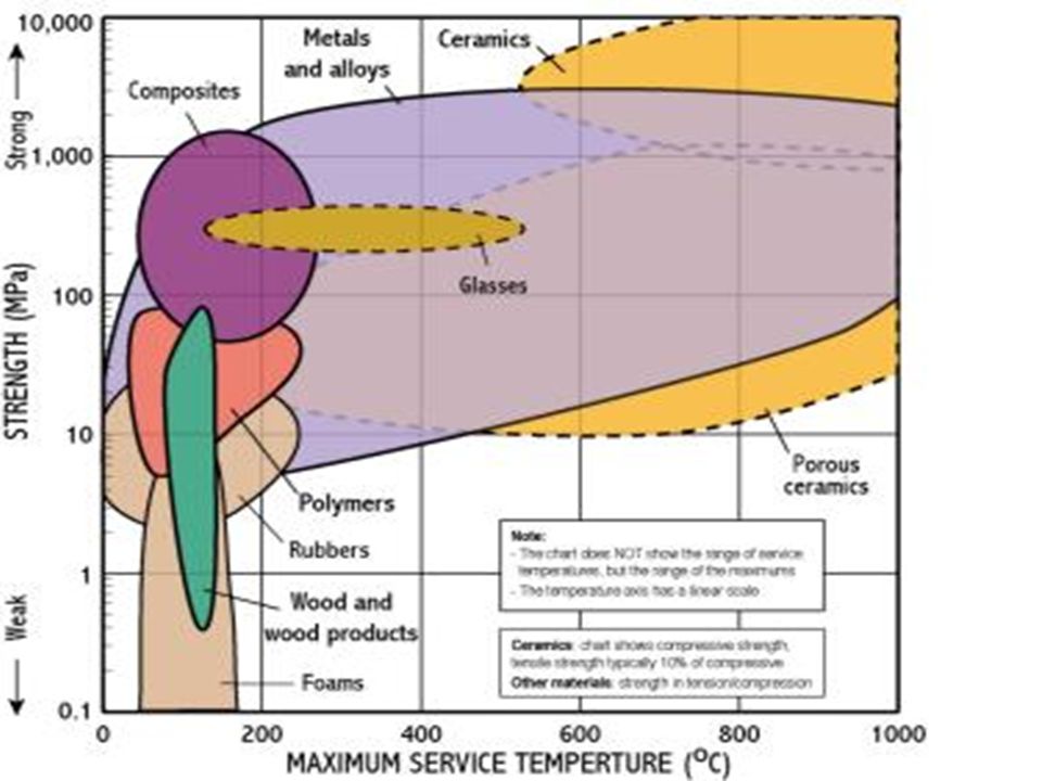
Ashby Material Selection Charts
E MCH 213D

Similar presentations


>")


