Download presentation
Presentation is loading. Please wait.

1
RAD TECH A WEEK 2 RADIOGRAPHIC EQUIPMENT Spring 2009

2
RADIOGRAPHIC EQUIPMENT RTA Week 2 Ch. 8 & 9 - pg (110 & 111)
")
3
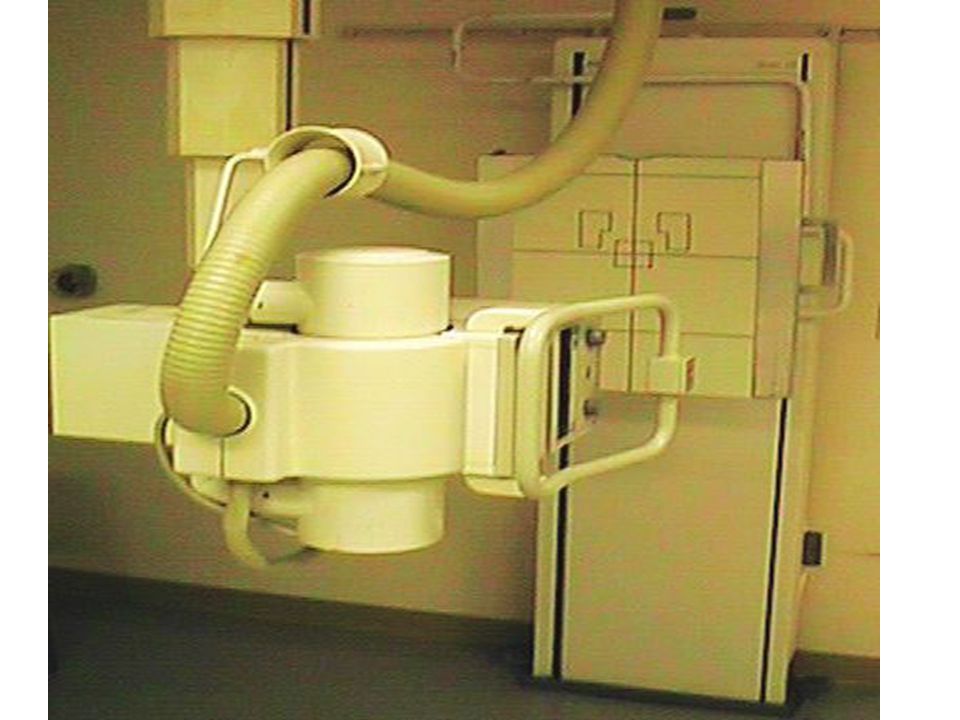
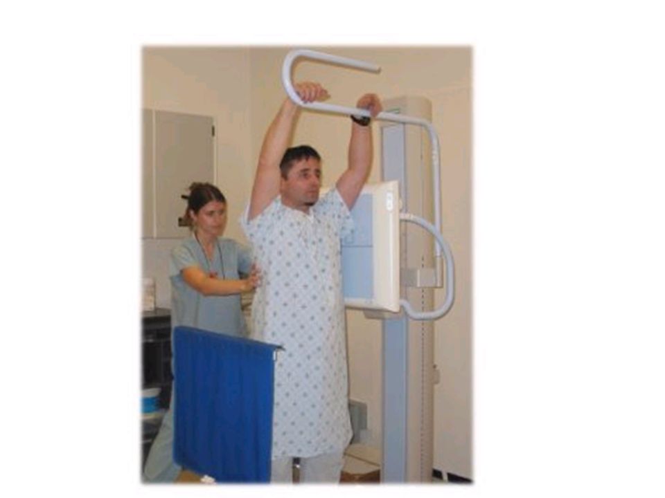
Radiographic Room

4
OBJECTIVES IDENTIFY GENERIC COMPONENTS OF THE RADIOGRAPHIC EQUIPTMENT DESCRIBE VARIOUS PLANES OF X-RAY TUBE AND TABLE MOVEMENT

5
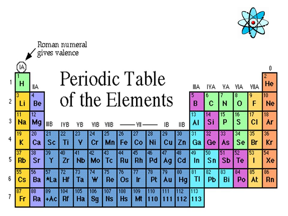
A look inside the body X-rays are a form of electromagnetic energy. X-rays have high enough energy to penetrate the human body leaving different densities on the image below Dependant on the Z# of the material

6
The Electromagnetic Spectrum X-rays have wavelengths much shorter than visible light, but longer than high energy gamma rays MEASURED IN ANGSTROM 0.1 – 0.5 FOR X-RAYS

7
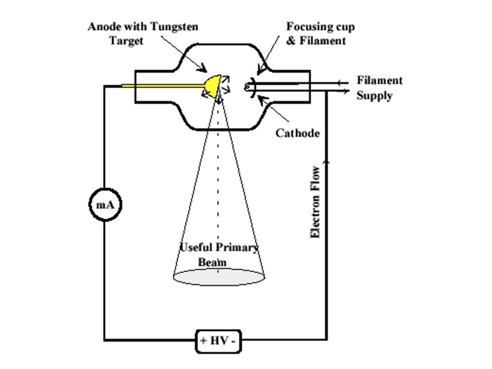
THE X-RAY TUBE The X-Ray tube is the single most important component of the radiographic system. It is the part that produces the X-rays

8
THE X-RAY TUBE GLASS ENCASED IN STURDY STEEL HOUSING PRIMARY COMPONENTS ANODE + & CATHODE --

9
How “X-rays” are created SEE: MAN MADE RADIATION (PG.93) TO PRODUCE X-RAYS YOU NEED: A SOUCE OF ELECTONS A FORCE TO MOVE THEM QUICKLY SOMETHING TO STOP THEM SUDDENLY
 TO PRODUCE X-RAYS YOU NEED: A SOUCE OF ELECTONS A FORCE TO MOVE THEM QUICKLY SOMETHING TO STOP THEM SUDDENLY")
10
PRODUCTION OF X RAYS Requirements: –a source of fast moving electrons –must be a sudden stop of the electrons’ motion –in stopping the electron motion, kinetic energy (KE) is converted to EMS energies Infrared (heat), light & x-ray energies
 is converted to EMS energies Infrared (heat), light & x-ray energies")
11
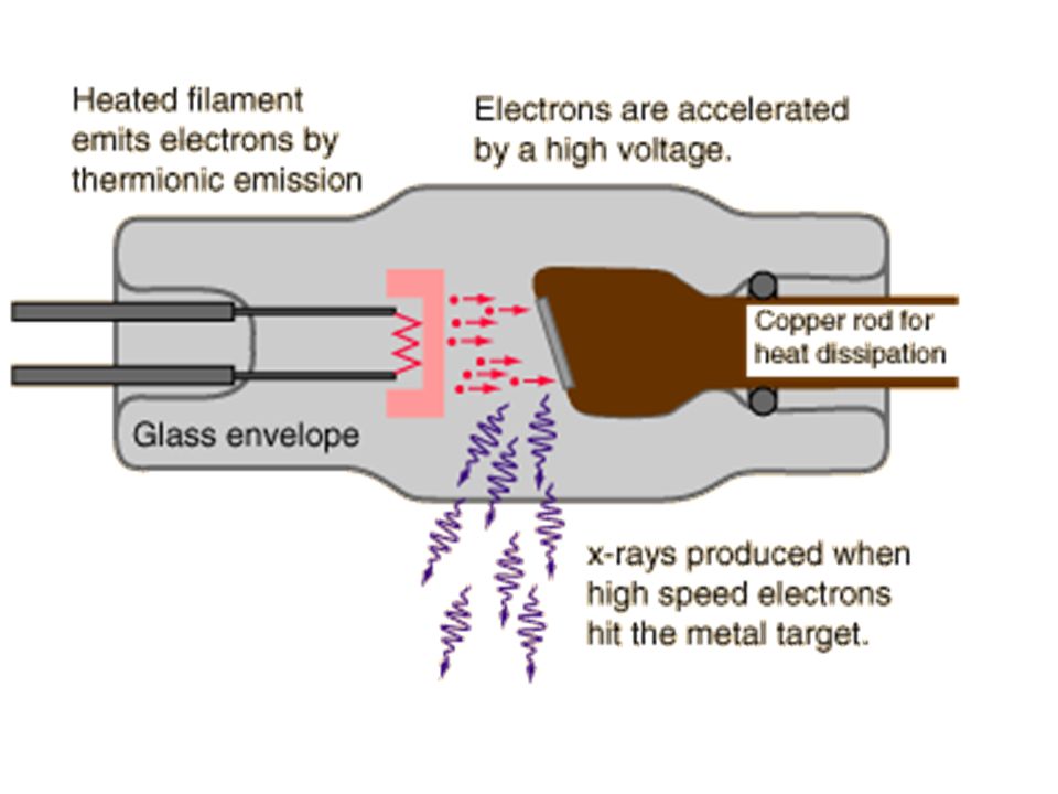
How Are X-rays Made? X-rays are produced when electrons strike a metal target. The electrons are released from the heated filament and accelerated by a high voltage towards the metal target. The X-rays are produced when the electrons collide with the atoms (electrons) of the metal target.
 of the metal target..")
12
How “X-rays” are created Power is sent to x-ray tube via cables mA (milliamperage) is sent to filament on cathode side. Filament heats up – electrons “boil off” Negative charge

13
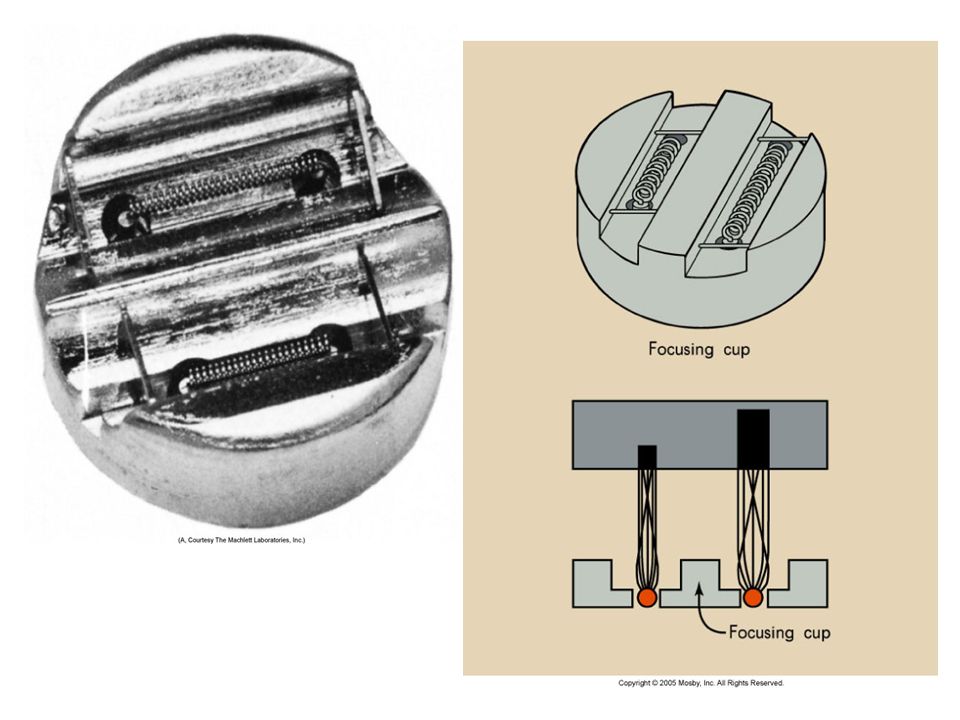
Cathode Filament –Dual-filament Focusing cup

14
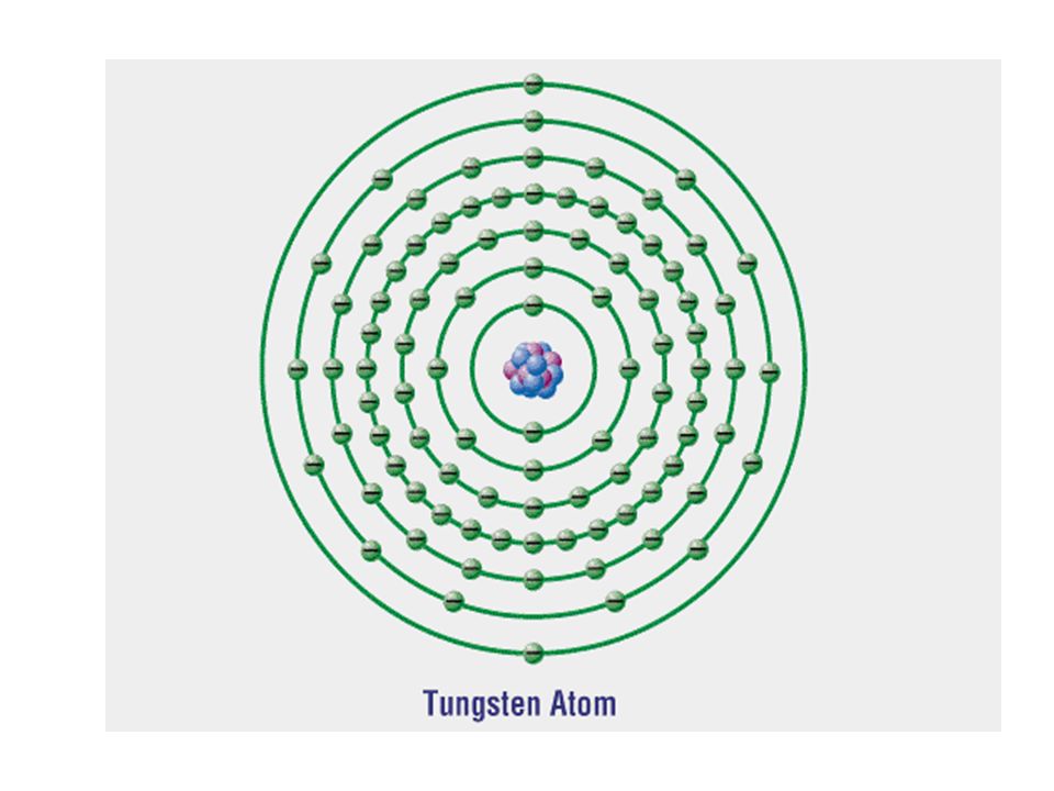
Tungsten Filaments are usually made of tungsten Tungsten provides higher thermionic emission than other metals Tungsten has a very high melting point

17
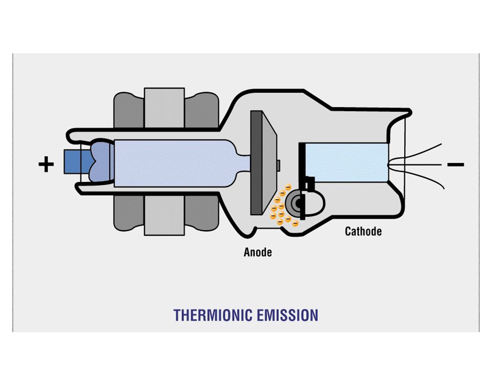
Filament When current (mA) is applied to the coil of wire electron are ejected The outer-shell electrons of the filament atom are “boiled off”. –This is known as thermionic emission

19
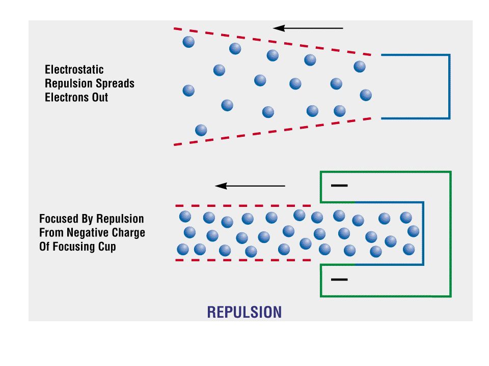
Focusing cup The filament is embedded in a metal cup that has a negative charge Boiled off e- tend to spread out due to electrostatic repulsion. The focusing cup confines the e- cloud to a small area

22
How “X-rays” are created Positive voltage (kVp) is applied to ANODE Negative electrons = attracted across the tube to the positive ANODE. Electrons “slam into” anode – suddenly stopped. X-RAY PHOTONS ARE CREATED

23
Mechanical support for the target

24
Anodes - Target Cu W Common target material is Tungsten Electrons interact with W – photons created Molybdenum or Graphite base Rotating Anodes 2” to 5” disk (focal track) Induction motor Speed 3000 to 10000 rpm
 Induction motor Speed 3000 to rpm")
26
e- X-ray Production electrons move at high speed (kV) collide with target on anode kV of electrons converted to x rays & heat electrons anode target
 collide with target on anode kV of electrons converted to x rays & heat electrons anode target")
27
How “X-rays” are created Electron beam is focused from the cathode to the anode target by the focusing cup Electrons interact with the electrons on the tungsten atoms of target material PHOTONS sent through the window PORT – towards the patient

28
\

29
TUBE HOUSING MADE OF LEAD & STEEL

30
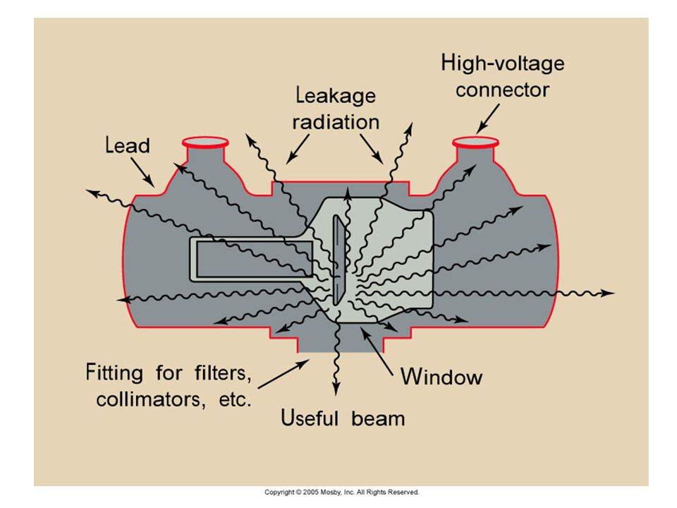
XRAY TUBE HOUSING MADE OF LEAD AND STEEL TO ABOSRB ANY STRAY RADIATION TO PREVENT X-RAY PHOTONS TO LEAK FROM THE TUBE

32
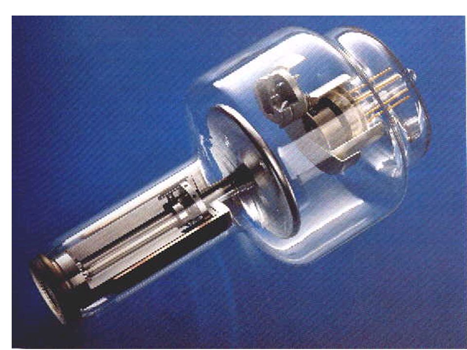
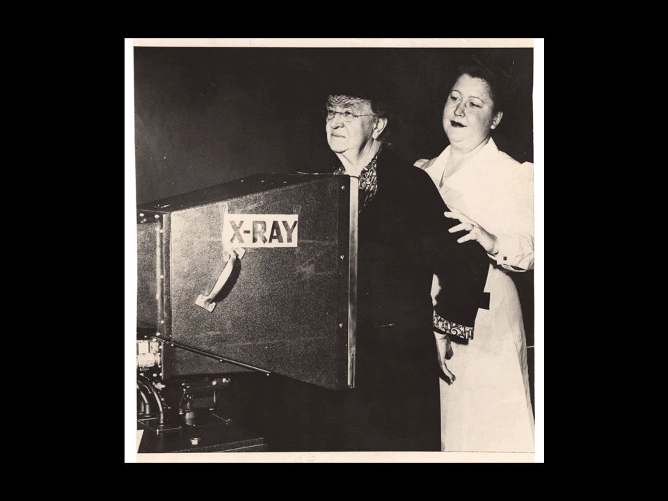
Early X-ray Tube

34
X-RAY TUBE MADE OF PYREX GLASS TO WITHSTAND HIGH HEAT LOAD IS GAS EVACUATED –(so electrons won’t collide with the air molecules in the tube)
")
35
Radiographic Equipment X-ray Tube Construction G F E D C A B

36
A. GLASS HOUSING (ENVELOPE) B. MOLYBDENUM NECK OF ANODE C. STATORS /ELECTROMAGNETS D.TUNGSTEN ANODE (FOCAL SPOT) E. WINDOW OR PORT FOR BEAM EXIT F. FILAMENT (CATHODE) G. FOCUSING CUP
 E. WINDOW OR PORT FOR BEAM EXIT F. FILAMENT (CATHODE) G. FOCUSING CUP.")
38
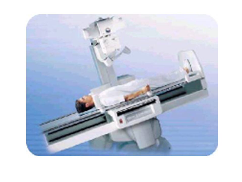
X-RAY TABLE

39
Radiographic tables Are designed to support the patient during a radiographic exam Comfort is not the primary concern Foam pads should be used if the patient will be required to be on the table for longer than 10 minutes

40
Tabletop Must be uniformly radiolucent to easily permit x-ray to pass through. Carbon fiber is used because it is strong and very little x-ray photons are absorbed. Usually tabletops are flat however some are curved

41
Tabletop Most tabletops are floating, some are motor-driven The brakes can be released usually by the technologist hand or foot The brakes are electromagnetic Floating table tops save significant amounts of time and strain on the technologist

42
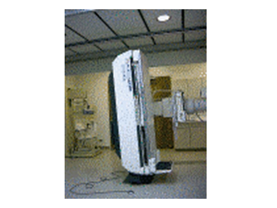
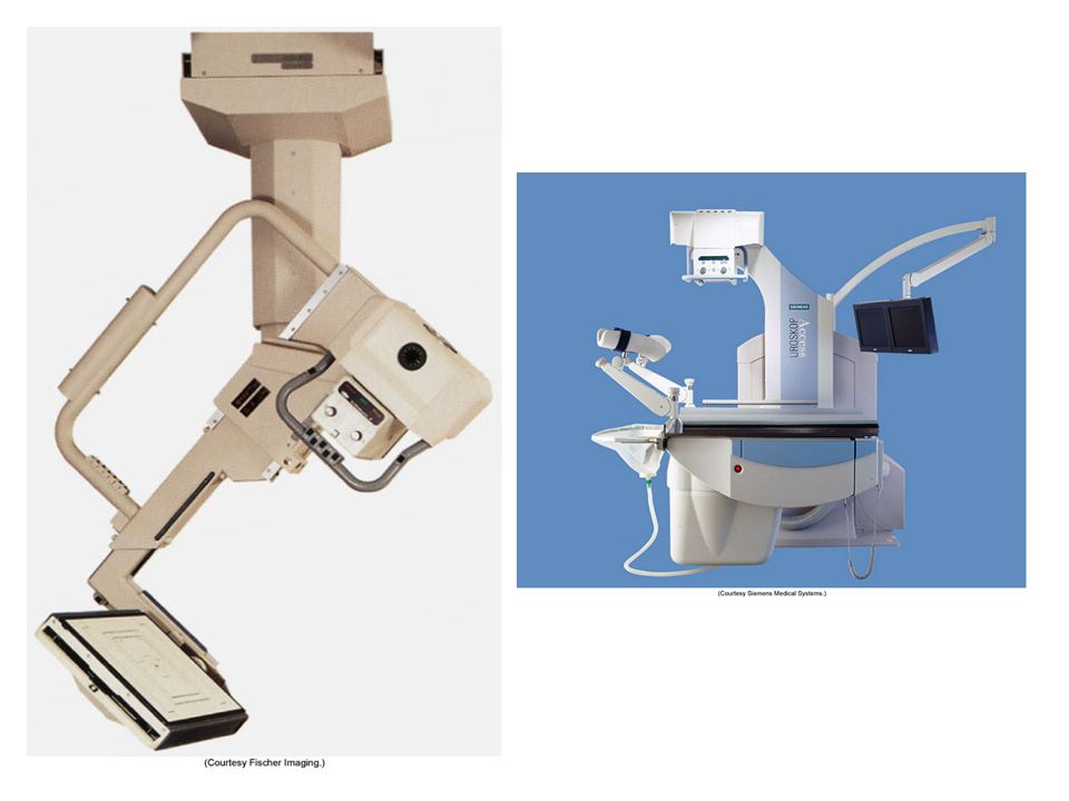
Tables Tilting rooms are designed for both diagnostic and fluoroscopic work –Tilting models usually tilt to 90 degrees in one direction and 15 – 30 degrees in the other direction –Tilting models include ancillary equipment; footboard, shoulder support, handgrips, compression bands

45
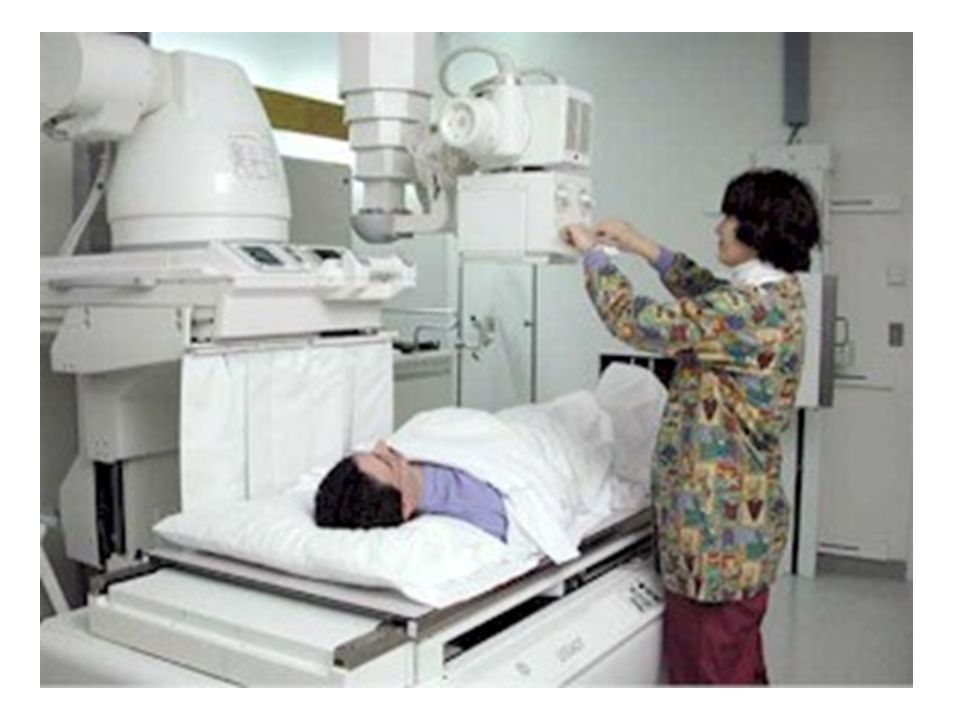
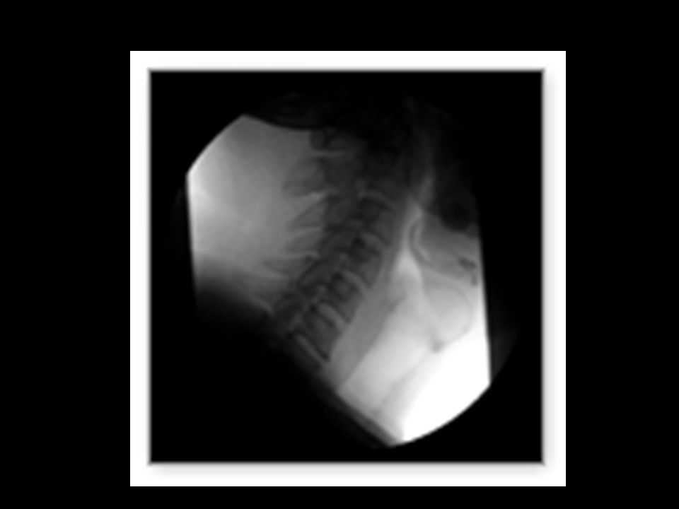
FLUOROSCOPY IMAGES IN MOTION

49
REMOTE ROOM & OLD CONVENTIONAL FLUORO

51
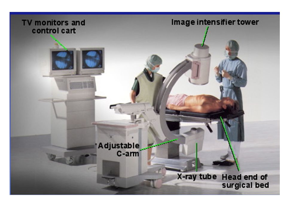
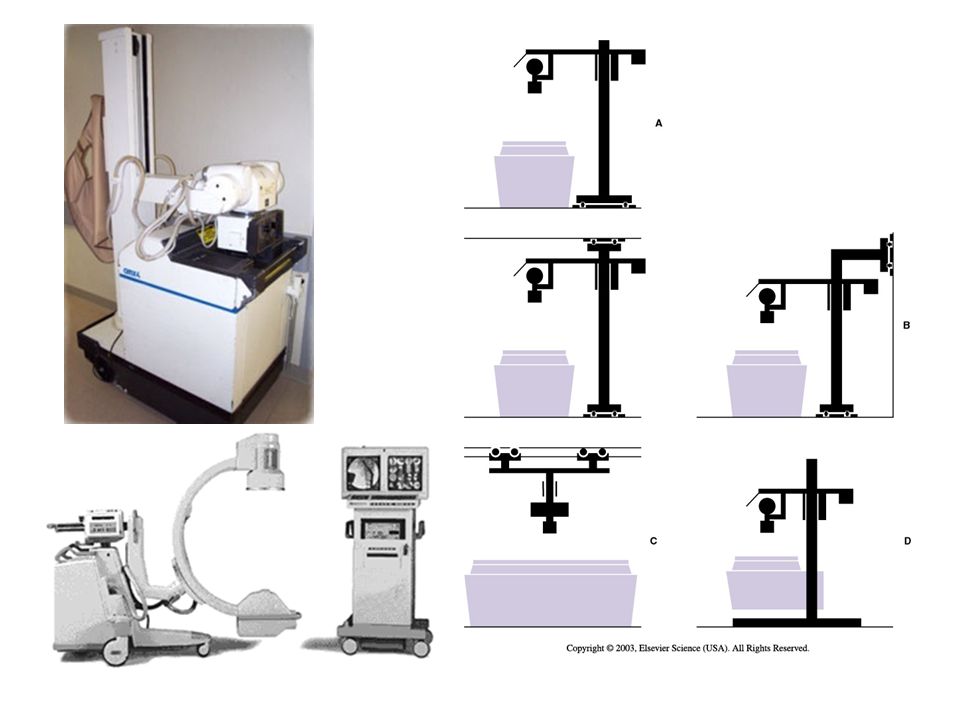
Tube Supports Designed to help technologists with various tube locations for creative imaging. Tube suspension systems are available in 5 versions: –ceiling mounted, floor-to-ceiling, floor, mobile and c-arm.

54
Tube Movement Longitudinal Transverse Vertical Angling or Rolling Rotating Telescoping

55
TABLE OR UPRIGHT BUCKY TRAY

56
The ‘BUCKY’ The bucky is the device in the table or chest board that holds the film cassette. The ‘bucky’ is like a drawer that opens and closes to insert and remove the film cassette.

58
Radiographic grid & bucky tray

59
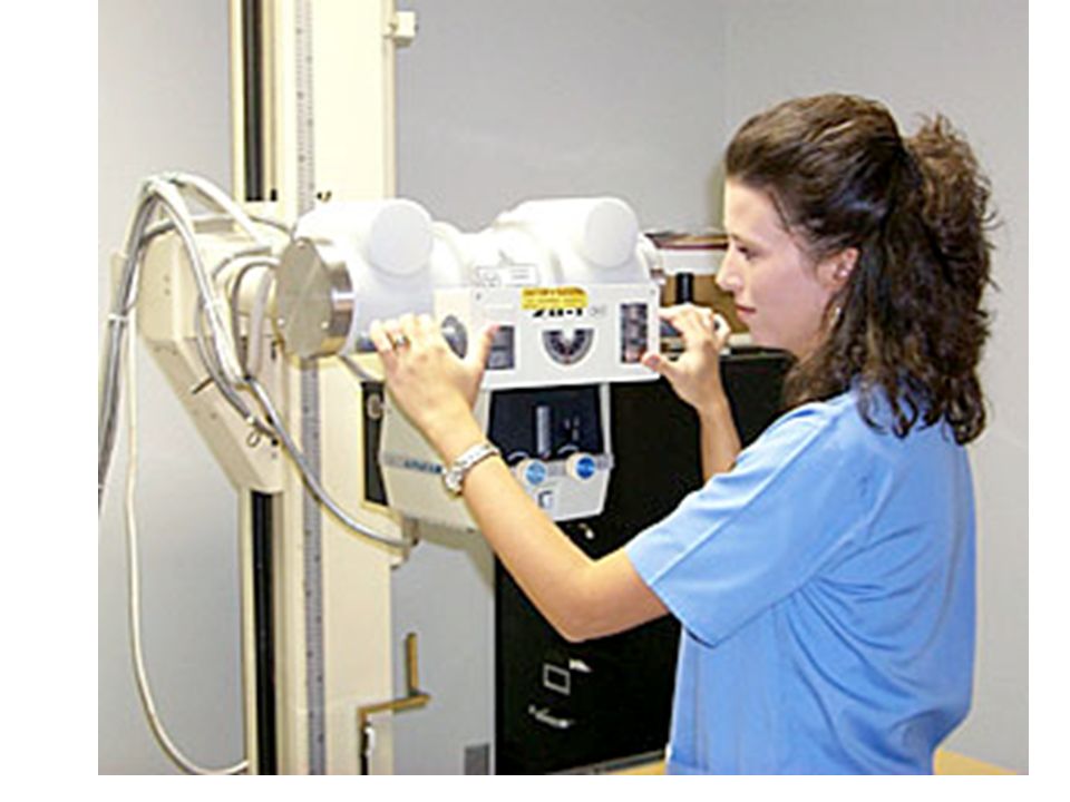
COLLIMATOR ATTACHES DIRECTLY BELOW THE X-RAY TUBE SERVES AS A X- RAY BEAM LIMITING DEVISE CONTROLS THE SIZE AND SHAPE OF X-RAY FIELD

60
Cone collimator

62
ALWAYS KEEP THE COLLIMATED AREA SMALLER THAN THE SIZE OF THE CASSETTE

64
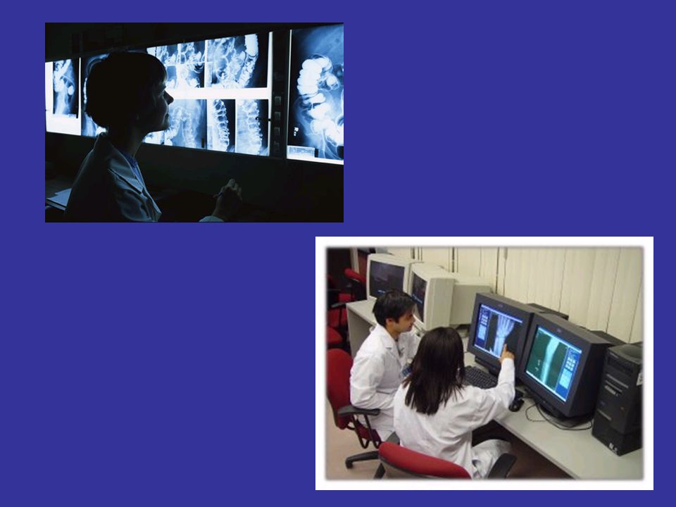
RADIOGRAPH PERMANENT RECORD MADE USING RADIATION –RADIO- RADIATION (usually x rays) –GRAPH PERMANENT RECORD (film)
 –GRAPH PERMANENT RECORD (film)")
66
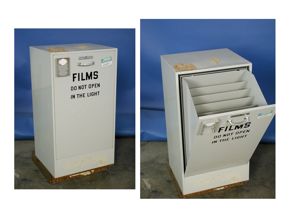
UNEXPOSED FILM PLACED IN A CASSETTE

67
CASSETTE or FILM HOLDER The CASSETTE is used to hold the film during examinations. It consist of front and back intensifying screens, and has a lead (Pb) backing. The cassette is light tight
 backing. The cassette is light tight.")
68
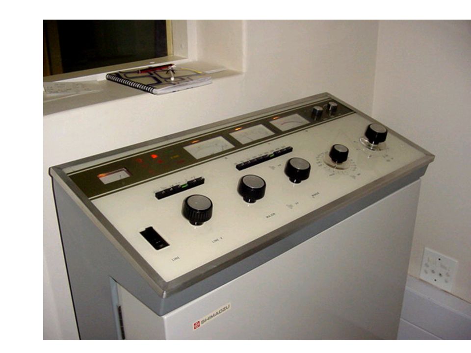
CONTROL CONSOLE GIVES THE TECHNOLOGIST CONTROL OF THE X-RAY MACHINE TECHNIQUE SELECTION Located OUTSIDE of the Radiographic Room

70
The Control Console The control console is device that allows the technologist to set technical factors (mAs & kVp) and to make an exposure. Only a legally licensed individual is authorized to energize the console.

71
“Technique” kVp, mAs (mA x s) What is set at the control panel How the “image” is created on the “film” or Image receptor (digital) kVp controls the “ENERGY” of the beam The Higher kVp – more penetrating Ranges is 50 -110 in Diagnostic x-ray
 What is set at the control panel How the image is created on the film or Image receptor (digital) kVp controls the ENERGY of the beam The Higher kVp – more penetrating Ranges is in Diagnostic x-ray")
72
“Technique” kVp, mAs (mA x s) mA- is the current in combination with the time – determines HOW LONG the beam will stay on Controls the density on the film/image
 mA- is the current in combination with the time – determines HOW LONG the beam will stay on Controls the density on the film/image")
74
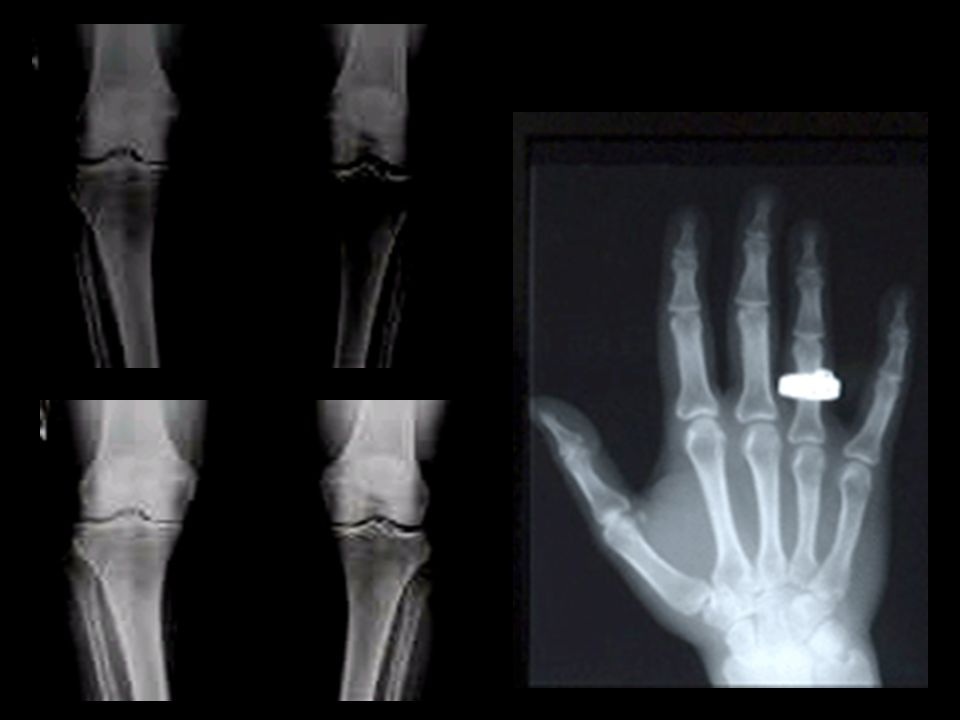
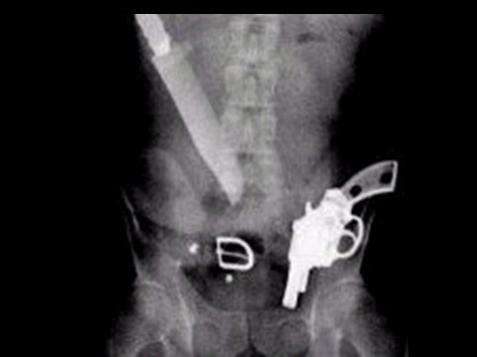
Why you see what you see The films or images have different levels of denisty – different shades of gray X-rays show different features of the body in various shades of gray. The gray is darkest in those areas that do not absorb X-rays well – and allow it to pass through the images are lighter in dense areas (like bones) that absorb more of the X-rays.
 that absorb more of the X-rays..")
76
IMAGES DENSITY = THE AMOUNT OF BLACKENING “DARKNESS” ON THE RADIOGRAPH - mAs controlled CONTRAST – THE DIFFERENCES BETWEEN THE BLACKS TO THE WHITES - kVp controlled

77
+ 30% + 50 % mas

78
kVp Changes

80
What is in the Darkroom?

82
Analog processor

83
Darkroom

84
Safe Light 15 Watts Red filter Must be 3-6 feet from counter top or feed tray of processor Used to be amber or orange filter

85
Computerized Radiography CR processor What a digital processor looks like No darkroom required

86
CHEST X-RAY IS THE MOST COMMONLY PERFORMED PROCEDURE Analog or Digital

88
Other x-ray stuff…. Positioning phantoms Pixie

89
Other x-ray stuff…. Positioning sponges Lead markers Gurney

91
RTA LAB 1 : EQUIPMENT Next week….. TOUR OF THE IONIZING LAB HERE ON CAMPUS. COMPLETE IN CLASS WORKSHEET FOR TERMINOLOGY

Similar presentations