Download presentation
Presentation is loading. Please wait.

1
DATABASE DESIGN LECTURE FOUR

2
Why Design a Database? Goal: To produce an information system that adds value for the user Reduce costs Increase sales/revenue Provide competitive advantage Objective: To understand the system To improve it To communicate with users and IT staff

3
Requirements Collection and Analysis This task results in a concise set of user requirements, which should be detailed and complete. The functional requirements should be specified, as well as the data requirements. Functional requirements consist of user operations that will be applied to the database, including retrievals and updates. Functional requirements can be documented using diagrams such as sequence diagrams, data flow diagrams, scenarios, etc.

4
Designing Systems Designs are a model of existing & proposed systems: They provide a picture or representation of reality They are a simplification Someone should be able to read your design (model) and describe the features of the actual system. You build models by talking with the users Identify processes Identify objects Determine current problems and future needs Collect user documents (views) Break complex systems into pieces and levels
 Break complex systems into pieces and levels.")
5
Conceptual Design Once the requirements are collected and analyzed, the designers go about creating the conceptual schema (model). Conceptual schema: concise description of data requirements of the users, and includes a detailed description of the entity types, relationships and constraints. The concepts do not include implementation details; therefore the end users easily understand them, and they can be used as a communication tool. The conceptual schema is used to ensure all user requirements are met, and they do not conflict.

6
Entity Relationship (ER) Model The most popular high-level conceptual data model is the ER model. It is frequently used for the conceptual design of database applications. The diagrammatic notation associated with the ER model, is referred to as the ER diagram. ER diagrams show the basic data structures and constraints.

7
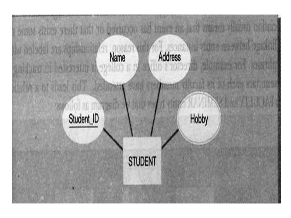
Entity Relationship (ER) cont… The basic object of an ER diagram is the entity. An entity represents a ‘thing’ in the real world. Examples of entities might be a physical entity, such as a student, a house, a product etc, or conceptual entities such as a company, a job position, a course, etc. Entities have attributes, which basically are the properties/characteristics of a particular entity.

8
Entity Relationship (ER) cont… EntityAttributesValues CarColorRed MakeVolkswagen ModelBora Year2000
 cont… EntityAttributesValues CarColorRed MakeVolkswagen ModelBora Year2000")
9
Entity Relationship (ER) cont… There are several types of entities. Including: Simple vs. Composite Single-valued vs. Multi-valued Stored vs. Derived

10
Simple vs. Composite Attributes Composite attributes can be divided into smaller subparts, which represent more basic attributes, which have their own meanings. A common example of a composite attribute is Address. Address can be broken down into a number of subparts, such as Street Address, City, Postal Code. Street Address may be further broken down by Number, Street Name and Apartment/Unit number. Attributes that are not divisible into subparts are called simple or atomic attributes.

11
Composite attributes can be used if the attribute is referred to as the whole, and the atomic attributes are not referred to. For example, if you wish to store the Company Location, unless you will use the atomic information such as Postal Code, or City separately from the other Location information (Street Address etc) then there is no need to subdivide it into its component attributes, and the whole Location can be designated as a simple attribute.
 then there is no need to subdivide it into its component attributes, and the whole Location can be designated as a simple attribute..")
12
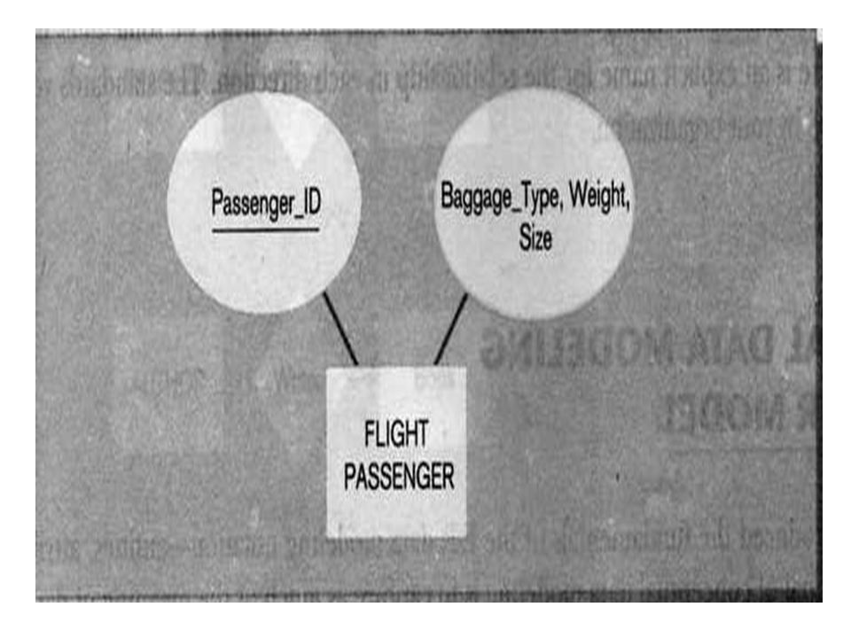
Single-Valued vs. Multi-valued Attributes Most attributes have a single value for each entity, such as a car only has one model, a student has only one ID number, an employee has only one date of birth. These attributes are called single-valued attributes. Sometimes an attribute can have multiple values for a single entity, for example, a doctor may have more than one specialty (or may have only one specialty), a customer may have more than one mobile phone number, or they may not have one at all. These attributes are called multi-valued attributes.
, a customer may have more than one mobile phone number, or they may not have one at all. These attributes are called multi-valued attributes..")
13
Stored vs. Derived Attributes If an attribute can be calculated using the value of another attribute, they are called derived attributes. The attribute that is used to derive the attribute is called a stored attribute. Derived attributes are not stored in the file, but can be derived when needed from the stored attributes.

14
Null Valued Attributes There are cases where an attribute does not have an applicable value for an attribute. For these situations, the value null is created. A person who does not have a mobile phone would have null stored at the value for the Mobile Phone Number attribute.

15
Null Valued Attributes….. Null can also be used in situations where the attribute value is unknown. There are two cases where this can occur, one where it is known that the attribute is valued, but the value is missing, for example eye color. Every person has eye color, but the information may be missing. Another situation is if mobile phone number is null, it is not known if the person does not have a mobile phone or if that information is just missing.

16
Complex Attributes Complex attributes are attributes that are nested in an arbitrary way. For example a person can have more than one residence, and each residence can have more than one phone, therefore it is a complex attribute that can be represented as: {Multi-valued attributes are displayed between braces}

17
Complex Attributes… (Complex Attributes are represented using parentheses) E.g. {AddressPhone({Phone(AreaCode, PhoneNumber)}, Address(StreetAddress(Number, Street, ApartmentNumber), City, code, country))}
}, Address(StreetAddress(Number, Street, ApartmentNumber), City, code, country))}.")
18
Entity Types An entity type defines a collection of entities that have the same attributes. Each entity type in the database is described by its name and attributes. The entity share the same attributes, but each entity has its own value for each attribute.

19
Entity Type Example Entity Type: Student Entity Attributes: StudentID, Name, Surname, Date of Birth, Department

20
Entity Set The collection of all entities of a particular entity type in the database at any point in time is called an entity set. The entity type (Student) and the entity set (Student) can be referred to using the same name.
 and the entity set (Student) can be referred to using the same name..")
21
Entity Set Example: Entity Type: Student Entity Set: [123, John, Smith, 12/01/1981, Computer Technology] [456, Jane, Doe, 05/02/1979, Mathematics] [789, Semra, Aykan, 02/08/1980, Linguistics]
![Entity Set Example: Entity Type: Student Entity Set: [123, John, Smith, 12/01/1981, Computer Technology] [456, Jane, Doe, 05/02/1979, Mathematics] [789, Semra, Aykan, 02/08/1980, Linguistics]](http://images.slideplayer.com/23/6622113/slides/slide_21.jpg "Entity Set Example: Entity Type: Student Entity Set: [123, John, Smith, 12/01/1981, Computer Technology] [456, Jane, Doe, 05/02/1979, Mathematics] [789, Semra, Aykan, 02/08/1980, Linguistics]")
22
KEY An important constraint on entities of an entity type is the uniqueness constraint. A key attribute is an attribute whose values are distinct for each individual entity in the entity set. The values of the key attribute can be used to identify each entity uniquely. Sometimes a key can consist of several attributes together, where the combination of attributes is unique for a given entity. This is called a composite key.

23
Composite keys should be minimal, meaning that all attributes must be included to have the uniqueness property. Specifying that an attribute as a key of an entity type means that the uniqueness property must hold true for every entity set of the entity type. An entity can have more than one key attribute, and some entities may have no key attribute. Those entities with no key attribute are called weak entity types. KEY….

24
Value Sets (Domains) of Attributes Each simple attribute of an entity is associates with a domain of values, or value set, which specifies the set of values that may be assigned to that attribute for each entity. For example, date of birth must be before today’s date, and after 01/01/1900, or the Student Name attribute must be a string of alphabetic characters. Value sets are not specified in ER diagrams.

25
Relationships Each time an attribute of one entity type refers to another entity type, some relationship exists. In ER diagrams, these references should be represented as relationships, rather than attributes. Relationships between entities are represented using a diamond shape.

26
Relationships…. Relationships are usually given a verb name, which specifies the relationship between two entities. If we look at the relationship between Employee and Department, an employee works for a department, therefore the relationship would be represented

27
Relationships…. Wor ks for Employee Depart ment

28
Degree of Relationship Type The degree of a relationship type is the number of participating entity types. Meaning if the relationship is between two entity types (Employee and Department), then the relationship is binary, or has a degree of two. If the relationship is between three participating entities, it has a degree of three, and therefore is a ternary relationship.
, then the relationship is binary, or has a degree of two. If the relationship is between three participating entities, it has a degree of three, and therefore is a ternary relationship..")
29
Degree of Relationship Type For example, if we have three entities, Supplier, Project and Part. Each part is supplied by a unique supplier, and is used for a given project within a company; the relationship “Supplies” is a ternary (degree of three) between Supplier, Project and Part, meaning all three participate in the supplies relationship.
 between Supplier, Project and Part, meaning all three participate in the supplies relationship..")
30
Degree of Relationship Type Supplies SupplierProject Part

31
Recursive Relationships If an employee has a supervisor, we need to include the relationship “Supervises”, however a supervisor is also an employee, therefore the employee entity type participates twice in the relationship, once as an employee and once as a supervisor, therefore we can specify two roles, employee and supervisor.

32
Recursive Relationships Employee Supervises supervisorsupervisee

33
Constraints on Relationship Types Relationship types have certain constraints that limit the possible combination of entities that may participate in relationship. An example of a constraint is that if we have the entities Doctor and Patient, the organization may have a rule that a patient cannot be seen by more than one doctor. This constraint needs to be described in the schema. There are two main types of relationship constraints, cardinality ratio, and participation.

34
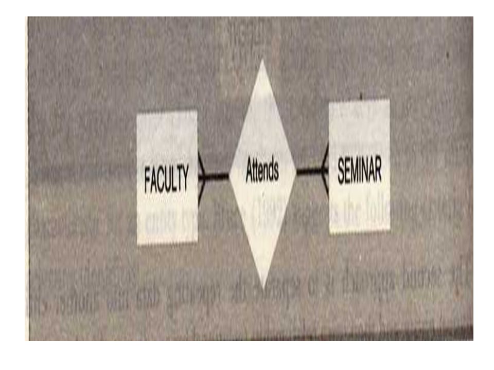
Cardinality for Binary Relationship Binary relationships are relationships between exactly two entities. The cardinality ratio specifies the maximum number of relationship instances that an entity can participate in. The possible cardinality ratios for binary relationship types are: 1:1, 1:N, N:1, M:N. Cardinality ratios are shown on ER diagrams by displaying 1, M and N on the diamonds. The ratio shown closest to an entity, represents the ratio the other entity has to that entity.

35
Participation Constraints and Existence Dependencies The participation constraint specifies whether the existence of an entity depends on its being related to another entity via the relationship type. The constraint specifies the minimum number of relationship instances that each entity can participate in. There are two types of participation constraints:

36
Total Participation If an entity can exist, only if it participates in at least one relationship instance, then that is called total participation, meaning that every entity in one set, must be related to at least one entity in a designated entity set. Also called existence dependency Total participation is represented by a double line, going from the relationship to the dependent entity

37
Total Participation An example would be the Employee and Department relationship. If company policy states that every employee must work for a department, then an employee can exist only if it participates in at lest one relationship instance (i.e. an employee can’t exist without a department).
..")
38
Partial Participation If only a part of the set of entities participate in a relationship, then it is called partial participation. Using the Company example, every employee will not be a manager of a department, so the participation of an employee in the “Manages” relationship is partial. Partial participation is represented by a single line.

39
Example: X is Customer, Y is Product, and Z is a ‘Purchases’ relationship. The figure below indicates the requirement that every customer purchases a product. Partial Participation - entity Y has partial participation in Relationship Z, meaning that only some instances of Y take part in the relationship. Relation ship Z X Y

40
Example: X is Customer, Y is Product, and Z is a ‘Purchases’ relationship. The figure below indicates the requirement that not every product is purchases by a customer. Some products may not be purchased at all.

41
Summary of ER, EER Diagram Notation » Strong Entities Weak Entities Attributes Multi Valued Attributes Composite Attributes Relationships Entity Name Relation ship Name

42
Attributes of Relationship Types Relationships can have attributes similar to entity types. For example, in the relationship Works_On, between the Employee entity and the Department entity we would like to keep track of the number of hours an employee works on a project. Therefore we can include Number of Hours as an attribute of the relationship

43
Attributes of Relationship Types Another example is for the “manages” relationship between employee and department, we can add Start Date as an attribute of the Manages relationship. For some relationships (1:1, or 1:N), the attribute can be placed on one of the participating entity types. For example the “Manages” relationship is 1:1, StartDate can either be migrated to Employee or Department.
, the attribute can be placed on one of the participating entity types. For example the Manages relationship is 1:1, StartDate can either be migrated to Employee or Department..")
44
Constraints - Cardinality 1:N – One Customer buys many products, each product is purchased by only one customer. N:1 - Each customer buys at most one product, each product can be purchased by many customers. Purchases Customer Product 1N Purchases Customer Product N1

45
Constraints – Cardinality…. 1:1 – Each customer purchases at most one product, each product is purchased by only one customer. M:N – Each customer purchases many products, each product is purchased by many customers. Purchases Customer Product 11 Purchases Customer Product MN

46
Weak Entity Types Entity types that do not have key attributes are called weak entity types. Entities that belong to a weak entity type are identified by being related to specific entities from another entity type in combination with one of their attribute values. This entity type is called an identifying or owner entity type.

47
Weak Entity Types…. The relationship that relates the identifying entity type with the weak entity type is called an identifying relationship. A weak entity type always has a total participation constraint with respect to the identifying relationship, because a weak entity cannot exist without its owner. Not all existence dependencies result in a weak entity type; if an entity has a key attribute then it is not a weak entity.

48
Weak Entity Types Has BookCopy

49
For example, lets assume in a library database, we have an entity type Book. For each book, we keep track of the author, ISBN, and title. The library may own several copies of the same book, and for each copy, it keeps track of the copy number (a different copy number for each copy of a given book) and price of each copy.
 and price of each copy..")
50
Weak Entity Types Because the copy number is only unique for each book (meaning Book 123 may have copy 1, copy 2, copy 3, and book 456 may also have copy 1, copy 2 and copy 3) and not for all copies of all books, it cannot be considered unique for each copy. Therefore because the Copy entity does not have a key attribute, it is considered a weak entity type, an is identified by being related to the Book entity. The book entity is the identifying entity, and the relationship is the identifying relationship.

51
Weak Entity Types Because a copy cannot exist without the owner (Book) the Copy entity type has a total participation constraint with respect to the identifying relationship. The partial key of the Copy entity is Copy Number, for each owner entity Book, the Copy Number uniquely identifies the copy.

52
Min-Max Notation Before we saw that to specify structural constraints (cardinality) we used the M:N notation. An alternate notation involves specifying a pair of integers, which are used to specify the minimum and maximum participation of each entity type in the form of (min, max)
.")
53
Min-Max Notation A minimum participation of 0 indicates partial participation (meaning that there may be some entities that do not participate in the relationship) A minimum participation of 1 or more indicates total participation, meaning that each entity must participate in exactly/at least one- relationship type.
 A minimum participation of 1 or more indicates total participation, meaning that each entity must participate in exactly/at least one- relationship type.")
54
The (min, max) notation (1,1) (0,1) (1,N) (1,1)
 notation (1,1) (0,1) (1,N) (1,1)")
55
ER DIAGRAM – Entity Types are: EMPLOYEE, DEPARTMENT, PROJECT, DEPENDENT

56
COMPANY ER Schema Diagram using (min, max) notation
 notation")
57
Designing an ER Diagram Consider the following set of requirements for a University database. Design an ER diagram for this application: The university keeps track of each student's name, student number, social security number, current address and phone number, permanent address and phone number, birthdate, sex, class (freshman, graduate), major department, minor department (if any), degree program (B.A., B.S.,... Ph.D.). Some user applications need to refer to the city, state, and zip code of the student's permanent address and to the student's last name. Both social security number and student number are unique for each student. All students will have at least a major department. Each department is described by a name, department code, office number, office phone, and college. Both the name and code have unique values for each department. Each course has a course name, description, course number, number of credits, level and offering department. The course number is unique for each course. Each section has an instructor, semester, year, course, and section number. The section number distinguishes sections of the same course that are taught during the same semester/year; its value is an integer (1, 2, 3,... up to the number of sections taught during each semester). A grade report must be generated for each student that lists the section, letter grade, and numeric grade (0,1,2,3, or 4) for each student and calculates his or her average GPA.
, major department, minor department (if any), degree program (B.A., B.S.,... Ph.D.). Some user applications need to refer to the city, state, and zip code of the student s permanent address and to the student s last name. Both social security number and student number are unique for each student. All students will have at least a major department. Each department is described by a name, department code, office number, office phone, and college. Both the name and code have unique values for each department. Each course has a course name, description, course number, number of credits, level and offering department. The course number is unique for each course. Each section has an instructor, semester, year, course, and section number. The section number distinguishes sections of the same course that are taught during the same semester/year; its value is an integer (1, 2, 3,... up to the number of sections taught during each semester). A grade report must be generated for each student that lists the section, letter grade, and numeric grade (0,1,2,3, or 4) for each student and calculates his or her average GPA..")
58
University ER Diagram Student Class StudentID SSN Sex Zip Degree City Birth date State Name Address Department DNameDCode OfficeNumber OfficePhone College Course CName CourseDesc CNumber Credits Section InstructorYear Semester SectionNumber GPA Numeric Grade Letter Grade Grade_Report Belong_To Offer Minor In Major In

59
SUMMARY OF ER-DIAGRAM: NOTATION FOR ER SCHEMAS Meaning ENTITY TYPE WEAK ENTITY TYPE RELATIONSHIP TYPE IDENTIFYING RELATIONSHIP TYPE ATTRIBUTE KEY ATTRIBUTE MULTIVALUED ATTRIBUTE COMPOSITE ATTRIBUTE DERIVED ATTRIBUTE TOTAL PARTICIPATION OF E 2 IN R CARDINALITY RATIO 1:N FOR E 1 :E 2 IN R STRUCTURAL CONSTRAINT (min, max) ON PARTICIPATION OF E IN R Symbol E1E1 R E2E2 E1E1 R E2E2 R (min,max) E N
 ON PARTICIPATION OF E IN R Symbol E1E1 R E2E2 E1E1 R E2E2 R (min,max) E N")
62
Multivalued attribute

64
Shipment Entity Type (An Associative Entity)
")
65
Notation for Supertype/Subtype Relationship

66
Example of Supertype/Subtype Hierarchy

67
Level – O Data Flow Diagram for the Web Store

68
Transforming an Entity Type to a Relation

69
Figure Representing a 1:N Relationship

70
Figure Representing M:N Relationship

71
CLASS DIAGRAMS Entity:Something in the real world that we wish to describe or track. Class: Description of an entity, that includes its attributes (properties) and behavior (methods). Object:One instance of a class with specific data. Property:A characteristic or descriptor of a class or entity. Method:A function that is performed by the class. Association:A relationship between two or more classes.
 and behavior (methods). Object:One instance of a class with specific data. Property:A characteristic or descriptor of a class or entity. Method:A function that is performed by the class. Association:A relationship between two or more classes..")
72
Associations General –One-to-one(1:1) –One-to-many(1:M) –Many-to-many(M:N) Relationships represent business rules –Sometimes common- sense –Sometimes unique to an organization Users often know current relationships, rarely future Objects related to objects –An employee can work in only one department –Many departments can work on many different products Objects related to properties –An employee can have only one name –Many employees can have the same last name 1* AnimalBreed ** performs TasksEmp 1* places SaleCust. 1* Purch. Order Supplier sent to

73
Class Diagram Class/Entity(box) Association/Relation ship –Lines –Minimum 0: optional 1: required –Maximum Arrows 1, M Customer Order Item 1 … 1 0 … * 1 … *..
 Association/Relation ship –Lines –Minimum 0: optional 1: required –Maximum Arrows 1, M Customer Order Item 1 … 1 0 … * 1 … *..")
74
Sample Association Rules (Multiplicity) An order must have exactly 1 customer, – 1 … 1Minimum of 1 – 1 … 1Maximum of 1 And at least one item. – 1 … *Minimum of 1 – 1 … *Maximum many An item can show up on no orders or many orders. – 0 … *Optional (0) – 0 … *Maximum many Customer Sale Item 1 … 1 0 … * 1 … *
 – 0 … *Maximum many Customer Sale Item 1 … 1 0 … * 1 … *.")
75
N-ary Associations Associations can connect more than two classes. Associations can become classes. –Events –Many-to-many –Need to keep data Example has two many-to-many relationships. –We know which components go into each product. –We know which employees worked on a product. We need to expand the relationships to show which employees installed which components into each product. –Each assembly entry lists one employee, one component, and one product. –By appearing on many assembly rows, the many-to-many relationships can still exist. Employee Component Product * * **

76
N-ary Association Example Employee Name... Component CompID Type Name Product ProductID Type Name * ** Assembly EmployeeID CompID ProductID Multiplicity is defined as the number of items that could appear if the other N-1 objects are fixed. Almost always “many.” 1 1 1

77
Rolling Thunder: Sales Customer CustomerID Phone FirstName LastName Address ZipCode CityID BalanceDue Customer Transaction CustomerID TransactionDate EmployeeID Amount Description Reference Retail Store StoreID StoreName Phone ContactFirstName ContactLastName Address ZipCode CityID Bicycle::Bicycle BicycleID … CustomerID StoreID … 1…1 0…* 1…1 0…* 0…1

78
Rolling Thunder: Bicycle Bicycle SerialNumber CustomerID ModelType PaintID FrameSize OrderDate StartDate ShipDate ShipEmployee FrameAssembler Painter Construction WaterBottleBrazeO n CustomName LetterStyleID StoreID EmployeeID TopTube ChainStay … 1…1 ModelType Description Paint PaintID ColorName ColorStyle ColorList DateIntroduced DateDiscontinue d LetterStyle LetterStyleID Description BicycleTubeUsed SerialNumber TubeID Quantity BikeParts SerialNumber ComponentID SubstituteID Location Quantity DateInstalled EmployeeID 1…* 0…* 1…1 0…* 1…1

79
Rolling Thunder: Assembly Bicycle::BikeParts SerialNumber ComponentID... 1…1 Component ComponentID ManufacturerID ProductNumber Road Category Length Height Width Description ListPrice EstimatedCost QuantityOnHand ComponentName AssemblyOrder Description GroupComponents GroupID ComponentID Groupo GroupID GroupName BikeType Bicycle:: BicycleTubeUsed SerialNumber TubeID Quantity TubeMaterial TubeID Material Description Diameter … 0…* 1…1 0…* 1…1 0…* 1…1 0…* 1…1

80
Rolling Thunder: Bicycle Bicycle SerialNumber CustomerID ModelType PaintID FrameSize OrderDate StartDate ShipDate ShipEmployee FrameAssembler Painter Construction WaterBottleBrazeO n CustomName LetterStyleID StoreID EmployeeID TopTube ChainStay … 1…1 ModelType Description Paint PaintID ColorName ColorStyle ColorList DateIntroduced DateDiscontinue d LetterStyle LetterStyleID Description BicycleTubeUsed SerialNumber TubeID Quantity BikeParts SerialNumber ComponentID SubstituteID Location Quantity DateInstalled EmployeeID 1…* 0…* 1…1 0…* 1…1

81
Rolling Thunder: Purchasing PurchaseOrder PurchaseID EmployeeID ManufacturerID TotalList ShippingCost Discount OrderDate ReceiveDate AmountDue 1…1 PurchaseItem PurchaseID ComponentID PricePaid Quantity QuantityReceived Manufacturer ManufacturerID ManufacturerName ContactName Phone Address ZipCode CityID BalanceDue ManufacturerTrans ManufacturerID TransactionDate Reference EmployeeID Amount Description Assembly:: Component ComponentID ManufacturerID ProductNumber 0…* 1…1 0…* 1…1 1…* 0…*

82
Rolling Thunder: Location City CityID ZipCode City State AreaCode Population1990 Population1980 Country Latitude Longitude Sales:: Customer CustomerID … CityID Sales:: RetailStore StoreID … CityID Employee:: Employee EmployeeID … CityID Purchasing:: Manufacturer ManufacturerID … CityID 0…* 1…1 0…* StateTaxRate State TaxRate 1…1 0…1

83
Rolling Thunder: Employee Employee EmployeeID TaxpayerID LastName FirstName HomePhone Address ZipCode CityID DateHired DateReleased CurrentManager SalaryGrade Salary Title WorkArea Bicycle:: Bicycle SerialNumber … EmployeeID ShipEmployee FrameAssembler Painter Bicycle:: BikeParts SerialNumber ComponentID … EmployeeID Purchasing:: PurchaseOrder PurchaseID … EmployeeID 1…1 0…* 1…1 0…* manager manages worker 0…* 0…1

84
CustomerID Phone FirstName LastName Address ZipCode CityID BalanceDue Customer CustomerID TransDate EmployeeID Amount Description Reference CustomerTrans StoreID StoreName Phone ContacFirstName ContactLastName Address Zipcode CityID RetailStore State TaxRate StateTaxRate SerialNumber CustomerID ModelType PaintID FrameSize OrderDate StartDate ShipDate ShipEmployee FrameAssembler Painter Construction WaterBottle CustomName LetterStyleID StoreID EmployeeID TopTube ChainStay HeadTubeAngle SeatTueAngle ListPrice SalePrice SalesTax SaleState ShipPrice FramePrice ComponentList Bicycle CityID ZipCode City State AreaCode Population1990 Population1980 Country Latitude Longitude Customer ModelType Description ComponentID ModelType Paint EmployeeID TaxpayerID LastName FirstName HomePhone Address ZipCode CityID DateHired DateReleased CurrentManager SalaryGrade Salary Title WorkArea Employee SerialNumber TubeID Quantity BicycleTube ModelType MSize TopTube ChainStay TotalLength GroundClearance HeadTubeAngle SeatTubeAngle ModelSize LetterStyle Description LetterStyle PurchaseID EmployeeID ManufacturerID TotalList ShippingCost Discount OrderDate ReceiveDate AmountDue PurchaseOrder SerialNumber TubeName TubeID Length BikeTubes SerialNumber ComponentID SubstituteID Location Quantity DateInstalled EmployeeID BikeParts PurchaseID ComponentID PricePaid Quantity QuantityReceived PurchaseItem ManufacturerID ManufacturerName ContactName Phone Address ZipCode CityID BalanceDue Manufacturer CompGroup GroupName BikeType Year EndYear Weight Groupo ComponentID ManufacturerID ProductNumber Road Category Length Height Width Weight Year EndYear Description ListPrice EstimatedCost QuantityOnHand Component ManufacturerID TransactionDate EmployeeID Amount Description Reference ManufacturerTrans TubeID Material Description Diameter Thickness Roundness Weight Stiffness ListPrice Construction TubeMaterial GroupID ComponentID GroupCompon ComponentName AssemblyOrder Description ComponentName PaintID ColorName ColorStyle ColorList DateIntroduced DateDiscontinued Rolling Thunder Combined

Similar presentations


 Model>")


 Modeling>")

 Model.>")
 ER Model.>")

 notation (1,1) (0,1) (1,N) (1,1). SUMMARY OF ER-DIAGRAM NOTATION FOR ER SCHEMAS Meaning ENTITY TYPE WEAK ENTITY TYPE RELATIONSHIP TYPE IDENTIFYING.>")


 Model Dr. Bernard Chen Ph.D. University of Central Arkansas.>")


 456-7890 University Name.>")
 www.desiamore.com/ifm B. Computer Science and BSc IT Year 1.>")
 Model Doç. Dr. Mehmet Göktürk src: Elmasri & Navanthe 6E Pearson Ed Slide Set.>")