Download presentation
Presentation is loading. Please wait.

1
1

2
2 Part II Remote Sensing using Reflected Visible and Infrared Radiation 602-MarCampus ClosedCh 17.1-17.3 04-Mar7 Surface reflectance – Land Surfaces I 05-MarLab 2 Contrast stretching and DN to reflectance conversion in ENVI 709-Mar7 extended, 8 Surface reflectance 11-Mar8 Water BodiesCh 19.1-19.6 12-MarLab 3 Visual Analysis and High Resolution Visual Analysis 816-MarSpring Break 18-Mar 923-Mar9 Detection of EM Radiation by a Vis/IR Radiometer 25-Mar10 Multispectral Remote Sensing Systems ICh 6,21 26-MarLab 4 Reflectance Spectra Compared to RS Images and Veg Index 1030-Mar Multispectral Remote Sensing Systems IICh 6,21 01-Apr11 Multispectral Remote Sensing Data Analyses ICh 12,17.9-17.10 02-AprLab 5 Image Classification 1106-Apr11 Multispectral Remote Sensing Data Analyses II 08-AprExam 2 – will cover material presented in Lectures 7-11 09-AprLab 6 Multi-temporal change detection

3
1. Key questions for designing space borne radiometers 2. Considerations for deploying a space borne radiometer 3. Problems in imaging over wide swaths 4. Summary of system tradeoffs 5. Categories of satellite radiometers 6. High Resolution Remote Sensing 3

4
Radiometer – An instrument that measures radiance in a specified wavelength region Spectroradiometer or spectrometer – An instrument that measures radiance continuously across a region of the EM spectrum or in multiple-bands across a region of the EM spectrum 4

5
What reflectance characteristics are you trying to measure? Spectral resolution How precisely do you have to measure radiance? Radiometric resolution How large are the features of interest? Spatial resolution and swath width How frequently and when do you have to measure the features of interest? Temporal resolution 5

6
Spectral Resolution – the wavelength regions of and bandwidths for a radiometer Radiometric Resolution - the sensitivity of a remote sensing detector to variations in the emitted, reflected or scattered EM energy that is being detected Spatial Resolution - The measure of the smallest distance (linear or angular separation) between objects that can be resolved by the sensor Temporal Resolution – the timing and frequency for collection of data by a satellite system 6
 between objects that can be resolved by the sensor Temporal Resolution – the timing and frequency for collection of data by a satellite system 6")
7
All scanning radiometers have an instantaneous field of view over which the sensor detects EM energy for a specific pixel 7

8
8 IFOV (in degrees, ) Radius of circle within IFOV, r = H tan /2 For very small IFOV, e.g., <<< 0.01º, r = H /2, where is in radians H Sensor r Fig. 5

9
If you are imaging over a very wide swath, then H will increase as you scan away from nadir, meaning the size of the IFOV on the ground will increase 9

10
Temporal resolution has three important components – a. How frequently you have to observe a specific area on the earth’s surface to capture variations over time of the phenomena being observed b. When during the year the phenomena you are monitoring occurs c. The diurnal (e.g., 24 hour) variations in the signature being observed 1. Variations in solar illumination 2. Variations in the occurrence of the phenomena 3. Variations in characteristics of the atmosphere 10
 variations in the signature being observed 1. Variations in solar illumination 2. Variations in the occurrence of the phenomena 3. Variations in characteristics of the atmosphere 10.")
11
How large of an area does the remote sensing system have to capture in order to collect data about the features or processes of interest? Swath widths of satellite remote sensing systems range between 7 and 2,500 kilometers Swath width + the orbital path of the satellite determine temporal resolution 11

12
1. Key questions for designing space borne radiometers 2. Considerations for deploying a space borne radiometer 3. Problems in imaging over wide swaths 4. Summary of system tradeoffs 5. Categories of satellite radiometers 6. High Resolution Remote Sensing 12

13
1. What is the size of the area or patch being detected by the satellite radiometer? 2. How frequently can a satellite view the same piece of ground on the earth’s surface? 3. How large an area is imaged by the sensor? 4. How much data are being recorded by the radiometer and how do we retrieve these data? 5. How do variations in surface and atmospheric conditions affect the data quality? 13

14
1. What is the size of the area or patch being detected by the satellite radiometer? Determined by A. The IFOV of the sensor B. The height of the satellite platform C. The scanning angles of the radiometer 14

15
1. What is the size of the area or patch being detected by the satellite radiometer? 2. How frequently can a satellite view the same piece of ground on the earth’s surface? 3. How large an area is imaged by the sensor? 4. How much data are being recorded by the radiometer and how do we retrieve these data? 5. How do variations in surface and atmospheric conditions affect the data quality? 15

16
1. The orbital time of the satellite 2. The width of the area being imaged by a satellite when it passes over the earth 16

17
17 A satellite in low earth orbit (~800 km) takes about 90 minutes to complete a single passage from equator to equator Fig. 6

18
18 H = 800 km Satellite Swath width = 2460 km Viewing angle of 57° off nadir to image swath Fig. 7

19
19 H = 800 km Satellite Swath width = 172 km Viewing angle of 6.1° off nadir to image swath Fig. 8

20
1. What is the size of the area or patch being detected by the satellite radiometer? 2. How frequently can a satellite view the same piece of ground on the earth’s surface? 3. How large an area is imaged by the sensor? 4. How much data are being recorded by the radiometer and how do we retrieve these data? 5. How do variations in surface and atmospheric conditions affect the data quality? 20

21
1. Ground receiving station within direct view of the satellite (to acquire global coverage requires a large number of stations) 2. On-board data recorders (requires reliable, large volume recorders) 3. Using data relay satellites – e.g., the TDRSS - Tracking and Data Relay Satellite System 21
 2. On-board data recorders (requires reliable, large volume recorders) 3. Using data relay satellites – e.g., the TDRSS - Tracking and Data Relay Satellite System 21.")
22
22 Wide Swath / Low Resolution Narrow Swath/ High Resolution Image Size2460 by 2460 km172 by 172 km Ground area size (resolution or pixel size) 1 by 1 km0.05 by 0.05 km (50 by 50 m) Number of radiometer channels44 Images per orbit 16228.8 Pixels per image per channel 6 million11.8 million Pixels per orbit per channel 96 million2.7 billion Pixels per orbit for all channels 384 million10.8 billion High resolution, wide swath – pixels per orbit for all channels 155 billion Data per day 2.5 trillion Data per month 743 trillion
 1 by 1 km0.05 by 0.05 km (50 by 50 m) Number of radiometer channels44 Images per orbit Pixels per image per channel 6 million11.8 million Pixels per orbit per channel 96 million2.7 billion Pixels per orbit for all channels 384 million10.8 billion High resolution, wide swath – pixels per orbit for all channels 155 billion Data per day 2.5 trillion Data per month 743 trillion")
23
1. What is the size of the area or patch being detected by the satellite radiometer? 2. How frequently can a satellite view the same piece of ground on the earth’s surface? 3. How large an area is imaged by the sensor? 4. How much data are being recorded by the radiometer and how do we retrieve these data? 5. How do variations in surface and atmospheric conditions affect the data quality? 23

24
In most regions with significant vegetation, there is a diurnal variation in atmospheric moisture and cloud cover that is driven by evapo-transpiration by plants In many areas, the resulting cloud formation hinders viewing of the earth’s surfaces over land areas by the early afternoon Because of this, many sensors schedule fly-over times between 10 am and noon 24

25
1. Key questions for designing space borne radiometers 2. Considerations for deploying a space borne radiometer 3. Problems in imaging over wide swaths 4. Summary of system tradeoffs 5. Categories of satellite radiometers 6. High Resolution Remote Sensing 25

26
1. The size of your ground footprint gets bigger as the angle off nadir increases 2. Atmospheric effects increase 3. The bidirectional reflectance at the surface often changes, e.g., the emittance from the surface for the same surface cover type changes 26

28
28 Fig. 10

29
1. The size of your ground footprint gets bigger as the angle off nadir increases 2. Atmospheric effects increase 3. The bidirectional reflectance at the surface often changes, e.g., the emittance from the surface for the same surface cover type changes 29

30
Effects of atmosphere on incoming/outgoing EM energy is proportional to distance traveled through the atmosphere As incidence angle increases, atmospheric effects (scattering, absorption, attenuation) increase Using wide swath width increases the requirements for atmospheric correction of the data 30
 increase Using wide swath width increases the requirements for atmospheric correction of the data 30")
31
31 Further information on this slide can be viewed at http://snrs.unl.edu/agmet/908/brdf_definition.htm

32
32

33
1. Key questions for designing space borne radiometers 2. Considerations for deploying a space borne radiometer 3. Problems in imaging over wide swaths 4. Summary of system tradeoffs 5. Categories of satellite radiometers 6. High Resolution Remote Sensing 33

34
Narrow-Swath, Higher Resolution Wide-Swath, Lower Resolution (-) Coverage only every 15 to 20 days (less if cloud cover exists) (+) Daily coverage of area (+) High resolution imagery (-) Low resolution imagery (-) Higher data volumes requires on- board recording or direct transmission (+) Lower data volumes result in less stringent recording/direct transmission requirements (+) Narrow viewing angle results in lower atmospheric / bi-directional scattering effects, and consistent across-swath resolution (-) Wider viewing angle results in greater atmospheric / bi-directional scattering effects, and variable across-swath resolution
 Coverage only every 15 to 20 days (less if cloud cover exists) (+) Daily coverage of area (+) High resolution imagery (-) Low resolution imagery (-) Higher data volumes requires on- board recording or direct transmission (+) Lower data volumes result in less stringent recording/direct transmission requirements (+) Narrow viewing angle results in lower atmospheric / bi-directional scattering effects, and consistent across-swath resolution (-) Wider viewing angle results in greater atmospheric / bi-directional scattering effects, and variable across-swath resolution")
35
1. Key questions for designing space borne radiometers 2. Considerations for deploying a space borne radiometer 3. Problems in imaging over wide swaths 4. Summary of system tradeoffs 5. Categories of satellite radiometers 6. High Resolution Remote Sensing 35

36
1. Wide swath, low resolution 1000-2600 km swath, 500 to 1100 m 2. Moderate swath, moderate resolution 100 to 200 km swath, 10 to 50 m resolution 3. Narrow swath, fine resolution 5 to 15 km swath, 1 to 4 m resolution 36

37
1. Key questions for designing space borne radiometers 2. Considerations for deploying a space borne radiometer 3. Problems in imaging over wide swaths 4. Summary of system tradeoffs 5. Categories of satellite radiometers 6. High Resolution Remote Sensing 37

38
Description of commercial high resolution remote sensing Ikonos Orbimage Quickbird Geoeye Applications of High resolution data National Security Preparation to respond to events Monitor activities Monitor Transportation Networks Urban Planning Tax assessments

39
39

40
Sensor Overview On September 24, 1999, an Athena II rocket carried the 1600- pound IKONOS satellite into a 684- kilometer (423-mile) polar orbit. IKONOS is the world’s first high- resolution commercial remote sensing satellite with a ground resolution of.82-meters. IKONOS is derived from the Greek word for "image." The IKONOS satellite is the world's first commercial satellite to collect black- and-white images with 1-meter resolution and multispectral imagery with 4-meter resolution. http://www.geoeye.com/corporate/constellation.htm

41
Sensor Characteristics It orbits the Earth every 98 minutes at an altitude of approximately 680 kilometers or 423 miles. IKONOS was launched into a sun-synchronous orbit, passing a given longitude at about the same local time (10:30 A.M.) daily. IKONOS can produce 1-meter imagery of the same geography every 3 days.
 daily. IKONOS can produce 1-meter imagery of the same geography every 3 days..")
42
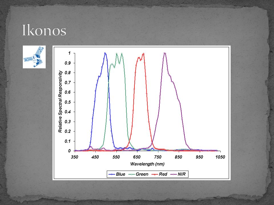
Spectral Range 1-meter black-and-white (panchromatic) 450 - 900 nm. 4-meter multispectral Blue: 450 - 520 nm Green: 510 - 600 nm Red: 630 - 700 nm Near IR: 760 - 850 nm Products Standard products include 1-meter black-and- white, 4-meter multispectral (all bands), 1-meter color (true color, false color, or 4-band), and a 1- meter and 4-meter data bundle. IKONOS image data is available in easy to use 8- bit or full dynamic range 11-bit format.
, 1-meter color (true color, false color, or 4-band), and a 1- meter and 4-meter data bundle. IKONOS image data is available in easy to use 8- bit or full dynamic range 11-bit format..")
43
Launch Date24 September 1999 Vandenberg Air Force Base, California, USA Operational LifeOver 7 years Orbit98.1 degree, sun synchronous Speed on Orbit7.5 kilometers per second Speed Over the Ground6.8 kilometers per second Number of Revolutions Around the Earth 14.7 every 24 hours Orbit Time Around the Earth98 minutes Altitude681 kilometers ResolutionNadir: 0.82 meters panchromatic 3.2 meters multispectral 26° Off-Nadir 1.0 meter panchromatic 4.0 meters multispectral Image Swath11.3 kilometers at nadir 13.8 kilometers at 26° off-nadir Equator Crossing TimeNominally 10:30 a.m. solar time Revisit TimeApproximately 3 days at 40° latitude Dynamic Range11-bits per pixel Image BandsPanchromatic, blue, green, red, near IR

44
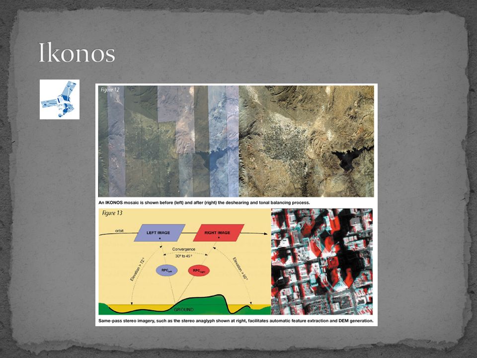
Standard IKONOS Stereo products include: Stereo 1-meter Black-and-White Stereo 1-meter Color Stereo imagery is available for IKONOS 1-meter Reference and Precision products. Imagery pairs are delivered with a Rational Polynomial Coefficient (RPC) camera model file. The RPC file enables photogrammetric processing, creation of digital terrain models and 3- dimensional measurement with popular software packages.
 camera model file. The RPC file enables photogrammetric processing, creation of digital terrain models and 3- dimensional measurement with popular software packages..")
49
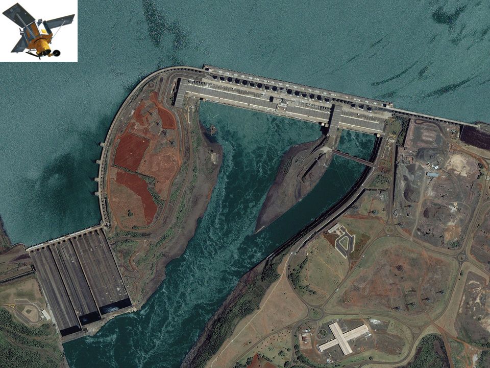
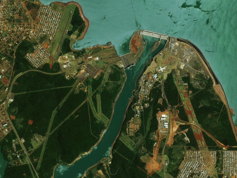
Itaipu Dam

53
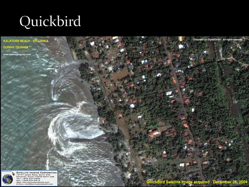
High-resolution data products and services to help organizations: Monitor, plan and prepare for disasters and emergencies Prepare response efforts for natural, terrorist and unintentional events Analyze information and provide relevance Provide for preventative action and timely response resulting in reduced consequences Evaluate critical infrastructures Monitor border and transportation activities Actively support first responders, related military organizations, citizens and non-government organizations Support efficiency and options for recovery

54
On June 26, 2003, a Pegasus XL successfully launched OrbView-3 into a 470-kilometer (292-mile) sun-synchronous orbit. The satellite is capable of providing one-meter resolution panchromatic and four-meter resolution multispectral imagery.

55
The Pegasus's three Orion solid motors were originally developed for the cancelled Midgetman (a small ICBM to be launched from a trailer) by Hercules Aerospace (now Alliant Techsystems). For Pegasus use, wing and tail assemblies and a payload fairing were developed. Most of the Pegasus was designed by a design team led by Dr. Antonio Elias. The wing was designed by Burt Rutan. · Mass: 18,500 kg (Pegasus), 23,130 kg (Pegasus XL) · Length: 16.9 m (Pegasus), 17.6 m (Pegasus XL) · Diameter: 1.27 m · Wing span: 6.7 m Payload: 443 kg (1.18 m diameter, 2.13 m length)
, 23,130 kg (Pegasus XL) · Length: 16.9 m (Pegasus), 17.6 m (Pegasus XL) · Diameter: 1.27 m · Wing span: 6.7 m Payload: 443 kg (1.18 m diameter, 2.13 m length).")
56
Facts at a Glance Spatial Resolution 1 meter Panchromatic 4 meters Multispectral Spectral Range: Panchromatic 450-900 nm Multispectral Blue: 450-520 nm Green: 520-600 nm Red: 625-695 nm Near IR: 760-900 nm Swath Width 8 km Off-Nadir Imaging Up to 50 degrees Dynamic Range 11 bits per pixel Mission Life Expected > 7 years Revisit Time Less than 3 days Orbital Altitude 470 km Modal Crossing 10:30 A.M.

57
IMAGERY APPLICATIONS OrbView-3 is used for a wide variety of commercial and government applications. These applications include environmental impact assessments for engineering companies; infrastructure planning for utilities and telecommunications; urban planning in city and county governments; crop health assessment; exploration for oil, gas and mineral companies; habitat monitoring for environmental agencies; and surveillance and mission planning for national security agencies.

58
http://www.digitalglobe.com/

59
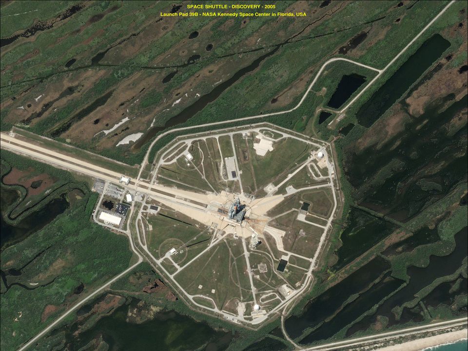
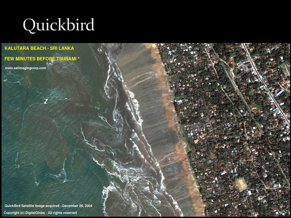
Was Highest resolution sensor available commercially 60-cm (2-ft) panchromatic at nadir 2.4-m (8-ft) multispectral at nadir Stable platform for precise location measurement 3-axis stabilized, star tracker/IRU/reaction wheels, GPS Fastest large area collection 16.5-km width imaging swath 128 Gbits on-board image storage capacity Off-axis unobscured design of QuickBird's telescope Large field-of-view High contrast (MTF) High signal to noise ratio 11 bit dynamic range Quantization11 bits
 panchromatic at nadir 2.4-m (8-ft) multispectral at nadir Stable platform for precise location measurement 3-axis stabilized, star tracker/IRU/reaction wheels, GPS Fastest large area collection 16.5-km width imaging swath 128 Gbits on-board image storage capacity Off-axis unobscured design of QuickBird s telescope Large field-of-view High contrast (MTF) High signal to noise ratio 11 bit dynamic range Quantization11 bits")
60
Depending upon orbital altitude, ground sample distances between 0.5 and 1.5 meters panchromatic and 2 to 8 meters multispectral can be achieved. The pushbroom camera, pointed and oriented by the spacecraft, is capable of imaging a strip of the Earth's surface between 14 and 34 km wide (specifications). The multispectral bands mimic the first four bands of the Landsat system (the visible NIR regions of the electromagnetic spectrum).
. The multispectral bands mimic the first four bands of the Landsat system (the visible NIR regions of the electromagnetic spectrum)..")
61
Launch DateOctober 18, 2001 Launch VehicleBoeing Delta II Launch LocationVandenberg Air Force Base, California, USA Orbit Altitude450 Km Orbit Inclination97.2º, sun-synchronous Speed7.1 Km/second - 25,560 Km/hour Equator Crossing Time10:30 a.m. (descending node) Orbit Time 93.5 minutes Revisit Time1-3.5 days depending on Latitude (30º off- nadir) Swath Width16.5 Km x 16.5 Km at nadir Metric Accuracy23-meter horizontal (CE90%) Digitization11 bits ResolutionPan: 61 cm (nadir) to 72 cm (25º off-nadir) MS: 2.44 m (nadir) to 2.88 m (25º off-nadir) Image BandsPan: 450 - 900 nm Blue: 450 - 520 nm Green: 520 - 600 nm Red: 630 - 690 nm Near IR 760 - 900 nm
 Orbit Time 93.5 minutes Revisit Time1-3.5 days depending on Latitude (30º off- nadir) Swath Width16.5 Km x 16.5 Km at nadir Metric Accuracy23-meter horizontal (CE90%) Digitization11 bits ResolutionPan: 61 cm (nadir) to 72 cm (25º off-nadir) MS: 2.44 m (nadir) to 2.88 m (25º off-nadir) Image BandsPan: nm Blue: nm Green: nm Red: nm Near IR nm.")
67
GeoEye again made history with the Sept. 6, 2008 launch of GeoEye-1—the world's highest resolution commercial earth-imaging satellite. GeoEye-1 is equipped with the most sophisticated technology ever used in a commercial satellite system. It offers unprecedented spatial resolution by simultaneously acquiring 0.41-meter panchromatic and 1.65-meter multispectral imagery. The detail and geospatial accuracy of GeoEye-1 imagery further expands applications for satellite imagery in every commercial and government market sector. A polar orbiting satellite, GeoEye-1 will make 12 to 13 orbits per day flying at an altitude of 684 kilometers or 425 miles with an orbital velocity of about 7.5 km/sec or 45,000 mi/hr.

68
Spatial Range: 0.41 m – 1.64 m Spectral Range: Panchromatic 450-900 nm Spectral Range Multispectral Blue: 450-520 nm Green: 520-600 nm Red: 625-695 nm Near IR: 760-900 nm Swath Width 15.2 km Off-Nadir Imaging Up to 60 degrees Dynamic Range 11 bits per pixel Mission Life Expected > 10 years Revisit Time Less than 3 days Orbital Altitude 684 km Modal Crossing 10:30 A.M.

69
GEOEYE-1 TECHNICAL INFORMATION Launch Vehicle Delta II Satellite Weight 1955 kg / 4310 lbs Satellite Storage and Downlink 1 Terabit recorder; X-band downlink (at 740 mb/sec or 150 mb/sec) Operational Life Fully redundant 7+ year design life; fuel for 15 years Satellite Modes of Operation Store and forward Real-time image and downlink Direct uplink with real-time downlink Orbital Altitude 684 kilometers / 425 miles Orbital Velocity About 7.5 km/sec or 45,000 mi/hr Inclination/Equator Crossing Time 98 degrees / 10:30am Orbit type/period Sun-synchronous / 98 minutes
 Operational Life Fully redundant 7+ year design life; fuel for 15 years Satellite Modes of Operation Store and forward Real-time image and downlink Direct uplink with real-time downlink Orbital Altitude 684 kilometers / 425 miles Orbital Velocity About 7.5 km/sec or 45,000 mi/hr Inclination/Equator Crossing Time 98 degrees / 10:30am Orbit type/period Sun-synchronous / 98 minutes")
70
1 meter 0.41 meter or 1.34 ft

71
71 Part II Remote Sensing using Reflected Visible and Infrared Radiation 602-MarCampus ClosedCh 17.1-17.3 04-Mar7 Surface reflectance – Land Surfaces I 05-MarLab 2 Contrast stretching and DN to reflectance conversion in ENVI 709-Mar7 extended, 8 Surface reflectance 11-Mar8 Water BodiesCh 19.1-19.6 12-MarLab 3 Visual Analysis and High Resolution Visual Analysis 816-MarSpring Break 18-Mar 923-Mar9 Detection of EM Radiation by a Vis/IR Radiometer 25-Mar10 Multispectral Remote Sensing Systems ICh 6,21 26-MarLab 4 Reflectance Spectra Compared to RS Images and Veg Index 1030-Mar Multispectral Remote Sensing Systems IICh 6,21 01-Apr11 Multispectral Remote Sensing Data Analyses ICh 12,17.9-17.10 02-AprLab 5 Image Classification 1106-Apr11 Multispectral Remote Sensing Data Analyses II 08-AprExam 2 – will cover material presented in Lectures 7-11 09-AprLab 6 Multi-temporal change detection

Similar presentations


-Polar Orbiting Environmental Satellite (POES) Orbital characteristics.>")


