Download presentation
Presentation is loading. Please wait.

1
Mechanical and optical properties of colloidal solutions 1.Kinetic properties of the dispersed systems 2.Investigation methods of the dispersed systems according to their kinetic properties. 3. Optical properties 4. Optical investigation methods of the dispersed systems Assistant Kozachok S.S. prepared

2
PROPERTIES OF COLLOIDAL SOLUTIONS The main characteristic properties of colloidal solutions are:

6
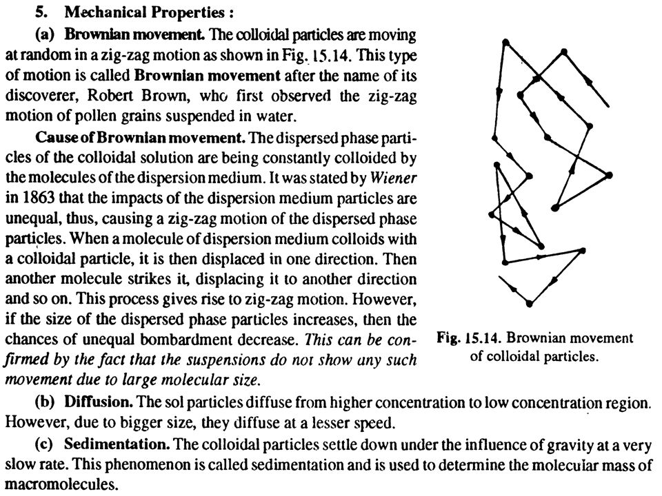
Brownian motion The motion of colloidal particle in dispersed medium Direction of the particle Average Brownian displacement

7
1. Fick's first law of diffusion (analogous with the equation of heat conduction) states that the mass of substance dm diffusing in the x direction in a time dt across an area S is proportional to the concentration gradient dc/dx at the plane in question: (The minus sign denotes that diffusion takes place in the direction of decreasing concentration.)
 states that the mass of substance dm diffusing in the x direction in a time dt across an area S is proportional to the concentration gradient dc/dx at the plane in question: (The minus sign denotes that diffusion takes place in the direction of decreasing concentration.).")
8
The proportionality factor D is called the diffusion coefficient. If – dc/dx = 1, S = 1 and dt = 1 D = dm, diffusion coefficient equals to the mass of substance diffusing in a time dt across an area S at the concentration gradient equals to 1. [D] = m 2 /s Einstein equation for spherical particles of the dispersed systems D = kT/6πηr diffusion coefficient is inversely proportsiynyry to particle radius

9
2. The rate of change of concentration at any given point is given by an exactly equivalent expression, Fick's second law:

10
Osmotic pressure of colloid solutions: 1. Osmotic pressure is very low: 2. Osmotic pressure is inversely proportional to the cube of radius of particles and is directly proportional to raise to the cube (third) power of its dispersion in the same dispersed medium:
 power of its dispersion in the same dispersed medium:.")
11
Hepp-Skatchard’s osmometr membrane solvent manometer Capillary with toluol Colloidal solution where 2.53·10 5 – constant at 25ºС π = [cm of water shaft]
![Hepp-Skatchard’s osmometr membrane solvent manometer Capillary with toluol Colloidal solution where 2.53·10 5 – constant at 25ºС π = [cm of water shaft]](http://images.slideplayer.com/23/6609629/slides/slide_11.jpg "Hepp-Skatchard’s osmometr membrane solvent manometer Capillary with toluol Colloidal solution where 2.53·10 5 – constant at 25ºС π = [cm of water shaft]")
12
Sedimentation equilibrium Sedimentation rate (Stock’s equation):
:")
13
Sedimentation analysis It consists of the obtaining sedimentation curve, that shows the dependence of the sediment mass m of the dispersed phases, which is settled down till certain time t. For monodispersed systems (with the same particles size) this dependence is line: m = Qυt/H where Q – general mass of the dispersed phases; H – initial height of column of the dispersed system. But all real dispersed systems are polydispersed and that’s why the sedimentation rate for different fraction is different: large particles settle down faster, smaller – slowly. Therefore sedimentation curve is bent to the axis of ordinates.
 this dependence is line: m = Qυt/H where Q – general mass of the dispersed phases; H – initial height of column of the dispersed system. But all real dispersed systems are polydispersed and that’s why the sedimentation rate for different fraction is different: large particles settle down faster, smaller – slowly. Therefore sedimentation curve is bent to the axis of ordinates..")
14
Tangent of the slope in specific point adjacents to the sedimentation determines the sedimentation velocity for the corresponding particles. Knowing the sedimentation rate of the corresponding particles of separated fractions can be determined the particle’s size (radius)
.")
15
Sedimentation curves mono- and poly-disperced systems Content of separated fraction

16
Q r Distribution curve of the particles of the dispersed phase according to the size

17
Sedimentometers: а) Phygorovski’ b) Vagner’ h, where m – mass settled down fraction, Q– general mass of powders
 Phygorovski’ b) Vagner’ h, where m – mass settled down fraction, Q– general mass of powders")
18
The scheme, which explains the color of the atmosphere Observation point Earth Sky blue Sun Sunset (Sunrise ) red Rayleigh equation:
 red Rayleigh equation:")
19
The intensity of the transmitted light beam is defined according to Rayleigh equation: where I 0 is the intensity of the incident light beam, I t is the intensity of the transmitted light beam, n 1 and n 0 – the refractive indices of the particles and the dispersion medium. λ - wavelength

20
Optical properties Optical microscopy Colloidal particles are often too small to permit direct microscopic observation. The resolving power of an optical microscope (i.e. The smallest distance by which two objects may be separated and yet remain distinguishable from each other) is limited mainly by the wavelength λ of the light used for illumination. The numerical aperture of an optical microscope is generally less than unity. With oil-immersion objectives numerical apertures up to about 1.5 are attainable, so that, for light of wavelength 600 nm, this would permit a resolution limit of about 200 nm (0.2 μ.m). Since the human eye can readily distinguish objects some 0.2 mm (200 μm) apart, there is little advantage in using an optical microscope, however well constructed, which magnifies more than about 1000 times. Further magnification increases the size but not the definition of the image.
 is limited mainly by the wavelength λ of the light used for illumination. The numerical aperture of an optical microscope is generally less than unity. With oil-immersion objectives numerical apertures up to about 1.5 are attainable, so that, for light of wavelength 600 nm, this would permit a resolution limit of about 200 nm (0.2 μ.m). Since the human eye can readily distinguish objects some 0.2 mm (200 μm) apart, there is little advantage in using an optical microscope, however well constructed, which magnifies more than about 1000 times. Further magnification increases the size but not the definition of the image..")
21
Particle sizes as measured by optical microscopy are likely to be in serious error for diameters less than c. 200 nm. Two techniques for overcoming the limitations of optical microscopy are of particular value in the study of colloidal systems. They are electron microscopy and dark-field microscopy – the ultramicroscope

22
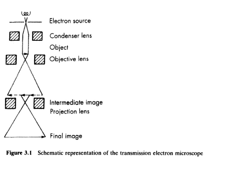
The transmission electron microscope To increase the resolving power of a microscope so that matter of colloidal (and smaller) dimensions may be observed directly, the wavelength of the radiation used must be reduced considerably below that of visible light. Electron beams can be produced with wavelengths of the order of 0.01 nm and focused by electric or magnetic fields, which act as the equivalent of lenses. The resolution of an electron microscope is limited not so much by wavelength as by the technical difficulties of stabilising high-tension supplies and correcting lens aberrations. The useful range of the transmission electron microscope for particle size measurement is c. 1 nm-5 μm diameter.

23
The use of the electron microscope for studying colloidal systems is limited by the fact that electrons can only travel unhindered in high vacuum, so that any system having a significant vapour pressure must be thoroughly dried before it can be observed. A small amount of the material under investigation is deposited on an electron-transparent plastic or carbon film (10-20 nm thick) supported on a fine copper mesh grid. The sample scatters electrons out of the field of view, and the final image can be made visible on a fluorescent screen.
 supported on a fine copper mesh grid. The sample scatters electrons out of the field of view, and the final image can be made visible on a fluorescent screen..")
25
Dark-field microscopy-the ultramicroscope Dark-field illumination is a particularly useful technique for detecting the presence of, counting and investigating the motion of suspended colloidal particles. It is obtained by arranging the illumination system of an ordinary microscope so that light does not enter the objective unless scattered by the sample under investigation. Lyophobic particles as small as 5-10 nm can be made indirectly visible in this way. The two principal techniques of dark-field illumination are the slit and the cardioid methods. 1) In the slit ultramicroscope of Siedentopf and Zsigmondy (1903) the sample is illuminated from the side by an intense narrow beam of light from a carbon-arc source
 In the slit ultramicroscope of Siedentopf and Zsigmondy (1903) the sample is illuminated from the side by an intense narrow beam of light from a carbon-arc source.")
27
Scheme ultramicroscope Lens Diaphragm Light source

28
2) The cardioid condenser (a standard microscope accessory) is an optical device for producing a hollow cone of illuminating light; the sample is located at the apex of the cone, where the light intensity is high (Figure 3.4).
 The cardioid condenser (a standard microscope accessory) is an optical device for producing a hollow cone of illuminating light; the sample is located at the apex of the cone, where the light intensity is high (Figure 3.4).")
29
Dark-field microscopy is, nevertheless, an extremely useful technique for studying colloidal dispersions and obtaining information concerning: 1. Brownian motion. 2. Sedimentation equilibrium. 3. Electrophoretic mobility. 4. The progress of particle aggregation. 5. Number-average particle size (from counting experiments and a knowledge of the concentration of dispersed phase). 6. Polydispersity (the larger particles scatter more light and therefore appear to be brighter). 7. Asymmetry (asymmetric particles give a flashing effect, owing to different scattering intensities for different orientations).
. 6. Polydispersity (the larger particles scatter more light and therefore appear to be brighter). 7. Asymmetry (asymmetric particles give a flashing effect, owing to different scattering intensities for different orientations)..")
30
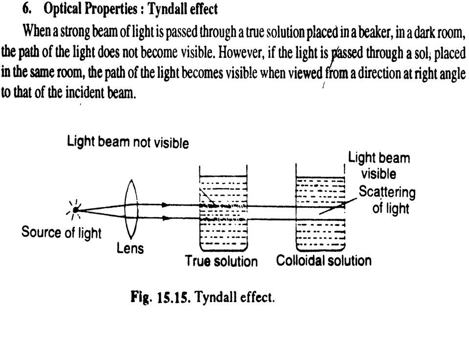
Light scattering When a beam of light is directed at a colloidal solution or dispersion, some of the light may be absorbed (colour is produced when light of certain wavelengths is selectively absorbed), some is scattered and the remainder is transmitted undisturbed through the sample. The Tyndall effect-turbidity All materials are capable of scattering light (Tyndall effect) to some extent. The noticeable turbidity associated with many colloidal dispersions is a consequence of intense light scattering. A beam of sunlight is often visible from the side because of light scattered by dust particles. Solutions of certain macromolecular materials may appear to be clear, but in fact they are slightly turbid because of weak light scattering. Only a perfectly homogeneous system would not scatter light; therefore, even pure liquids and dust-free gases are very slightly turbid.
 to some extent. The noticeable turbidity associated with many colloidal dispersions is a consequence of intense light scattering. A beam of sunlight is often visible from the side because of light scattered by dust particles. Solutions of certain macromolecular materials may appear to be clear, but in fact they are slightly turbid because of weak light scattering. Only a perfectly homogeneous system would not scatter light; therefore, even pure liquids and dust-free gases are very slightly turbid..")
31
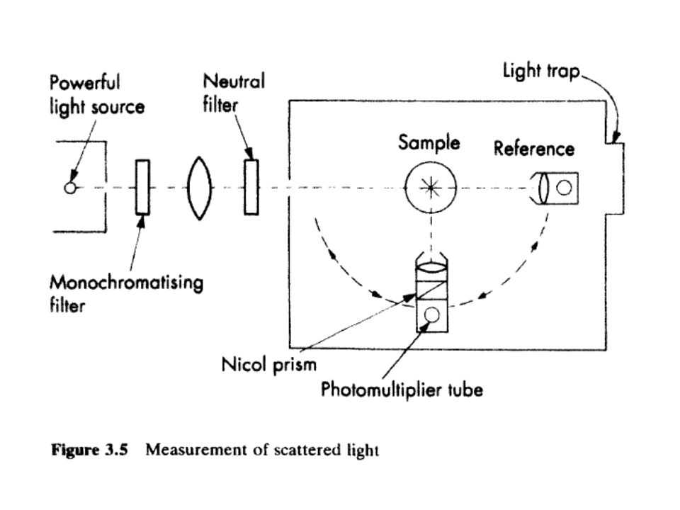
The turbidity of a material is defined by the expression where I 0 is the intensity of the incident light beam, I t is the intensity of the transmitted light beam, l is the length of the sample and τ is the turbidity. This expression is used in Turbidimetry. It is based on the measuring of the intensity of the transmitted light beam. Measurement of scattered light As we shall see, the intensity, polarisation and angular distribution of the light scattered from a colloidal system depend on the size and shape of the scattering particles, the interactions between them, and the difference between the refractive indices of the particles and the dispersion medium.

32
Light-scattering measurements are, therefore, of great value for estimating particle size, shape and interactions, and have found wide application in the study of colloidal dispersions, association colloids, and solutions of natural and synthetic macromolecules. The intensity of the light scattered by colloidal solutions or dispersions of low turbidity is measured directly. A detecting photocell is mounted on a rotating arm to permit measurement of the light scattered at several angles, and fitted with a polaroid for observing the polarisation of the scattered light (see Figure 3.5).
..")
34
Doty nephelometr Flasks containing colloidal solution Source of light Plate Limb photometer

35
Nephelometry is based on the measuring of the the intensity of the scattered light beam by the dispersed system. I t,1/ I t,2 = c 1 /c 2 ; I t,1 /I t,2 = V 1 /V 2 ; I t = k νV 2 I 0 = kCVI 0 where, k – constant, C = νV – volume concentration of the dispersed phase

Similar presentations


 Index of refraction v medium = c/n –the bending of light – refraction –total internal.>")

. What.>")


