Download presentation
Presentation is loading. Please wait.

1
Resistive-Inductive (RL) Circuits
AC Circuits I

2
Series RL Circuits Series circuits: A comparison (Magnitude)
IT = IR1 = IR2 IT = IL1=IL2 IT = IL=IR VT =VR1+VR2 VT = j(VL1 + VL2) |VT| = sqrt(VR2 + VL2) RT = R1+R2 XT = XL1 + XL2 |ZT| = sqrt(R2 + XL2)
 |VT| = sqrt(VR2 + VL2) RT = R1+R2. XT = XL1 + XL2. |ZT| = sqrt(R2 + XL2)")
3
Series RL Circuits Series Voltages

4
Series RL Circuits Series Voltages (Continued)
Since VL leads VR by 90°, the values of the component voltages are usually represented using phasors Phasor – a vector used to represent a value that constantly changes phase. Usually denoted in a polar form

5
Series RL circuits Series Impedance Polar form Polar form
Rectangular form Rectangular form

6
Example The component voltages shown below were measured using an ac voltmeter (HINT: rms values!!!). Calculate the source voltage for the circuit.

7
Example Calculate the total impedance for the circuit shown (remember Z = R +jXL , where XL=2πfL )
")
8
Phase Reference In a series RL circuit the current I and voltage across the resistor VR are considered to have 0o phase. Sometimes however (especially in the lab) the source voltage Vs is assumed to have 0o phase.
 the source voltage Vs is assumed to have 0o phase.")
9
Example Calculate the circuit impedance, and current in the circuit shown below I and Vs can be represented as either: (I lags Vs or Vs leads I)
 .")
10
Example Determine the voltage, current and impedance values for the circuit shown below

11
Voltage Dividers RL Voltage Dividers
In a series RL circuit where I(VR )is used as the 0o phase reference, Vs and ZT always have the same phase angle!!! where Zn = magnitude of R or XL Vn = voltage across the component
is used as the 0o phase reference, Vs and ZT always have the same phase angle!!! where. Zn = magnitude of R or XL. Vn = voltage across the component.")
12
Example Determine the voltages VL and VR in the circuit below

13
Example Calculate ZT, VL1 VL2 and VR for the circuit shown below.

14
Series RL Circuit Frequency Response
Frequency Response – used to describe any changes that occur in a circuit as a result of a change in operating frequency An increase in frequency causes XL to increase An increase in XL causes ZT and to increase An increase in ZT causes IT to decrease An increase in XL causes VL to increase An increase in VL causes VR to decrease

15
Power Power is also a complex quantity in AC circuits

16
Apparent, True and Reactive Power
Value Definition Resistive power (PR) The power dissipated by the resistance in an RL circuit. Also known as true power. Reactive power (PX) The value found using P = I2XL. Also known as imaginary power. The energy stored by the inductor in its electromagnetic field. PX is measured in volt-amperes-reactive (VARs) to distinguish it from true power. Apparent power (PAPP) The combination of resistive (true) power and reactive (imaginary) power. Measured in volt-amperes (VAs).
 The power dissipated by the resistance in an RL circuit. Also known as true power. Reactive power (PX) The value found using P = I2XL. Also known as imaginary power. The energy stored by the inductor in its electromagnetic field. PX is measured in volt-amperes-reactive (VARs) to distinguish it from true power. Apparent power (PAPP) The combination of resistive (true) power and reactive (imaginary) power. Measured in volt-amperes (VAs).")
17
Power Factor (PF) The ratio of resistive power to apparent power
 The ratio of resistive power to apparent power")
18
Example Calculate PR, PX and PAPP for the following circuit - (see slide 13)
")
19
Parallel RL Circuits Note that VS, IR and VR are all in phase
IL is 90o out of phase with (lags) VS, IR and VR. VS = VR1 = VR2 VS = VL1 = VL2 VT = VL= VR IT =IR1+IR2 IT = j(IL1 + IL2) |IT|= sqrt(IR2 + IL2) RT = 1/[ (1/R1 )+(1/R2)] XT = 1/[(1/XL1 ) + (1/XL2 )] XT = 1/[(1/R ) + (1/jXL )]
 VS, IR and VR. VS = VR1 = VR2. VS = VL1 = VL2. VT = VL= VR. IT =IR1+IR2. IT = j(IL1 + IL2) |IT|= sqrt(IR2 + IL2) RT = 1/[ (1/R1 )+(1/R2)] XT = 1/[(1/XL1 ) + (1/XL2 )] XT = 1/[(1/R ) + (1/jXL )]")
20
Parallel RL Circuits Branch Currents IL lags IR , VR and VS by 90º

21
Parallel RL Circuits Parallel Circuit Impedance
Impedance phase angle is positive since current phase angle is negative Angles of ZT and IT have the same magnitude but opposite signs Calculating Parallel-Circuit Impedance (polar form)
")
22
Parallel RL Circuits Calculating Parallel-Circuit Impedance
rectangular form approach:

23
Parallel RL Circuits Parallel-Circuit Frequency Response
The increase in frequency causes XL to increase The increase in XL causes: IL to decrease IT to increase ZT to increase The decrease in IL causes IT to decrease

24
Example 1 Calculate the total current for circuit (a) in both rectangular and polar forms Calculate total impedance of circuit (a) Repeat for circuit (b)
")
25
Example 2 (Rectangular)
Calculate the total impedance for circuit (a) in both rectangular and polar forms Calculate total current of circuit (a) Repeat for circuit (b)
 in both rectangular and polar forms. Calculate total current of circuit (a) Repeat for circuit (b)")
26
Example 2 (Polar) Calculate the total impedance for circuit (a) in both rectangular and polar forms Calculate total current of circuit (a) Repeat for circuit (b)
 Repeat for circuit (b)")
28
Series –Parallel RL Circuits
First collapse the parallel RL portion into a single impedance ZP If this single impedance is in polar form, convert it to rectangular form Add any resistances/ reactances in series with ZP to get ZT. Remember you cannot add complex numbers in their polar form. Always assume that IT is the zero Phase reference!! And that VS and ZT have the same phase i.e. Same assumption as for series RL circuit

29
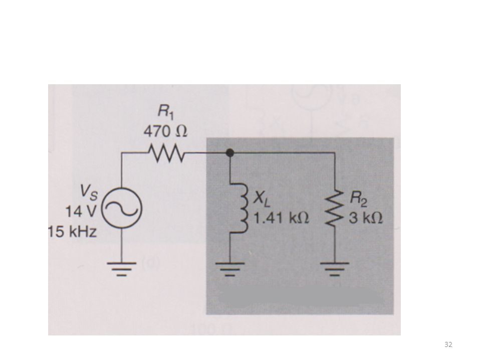
Example Calculate the Equivalent Impedance, the total current and the current in each branch of the parallel RL circuit shown below Now convert to rect and back to polar

30
Example Cont’d Knowing that
Remember in a series circuit, IT is the phase reference and VS and ZT always have the same phase!!!

31
Example Cont’d Alternatively using a current divider equation
Does IT = IL + IR2?

33
Remember!! For Series RL Circuits For Parallel RL Circuits
IT and VR are the 0o phase reference VS and ZT have the same phase For Parallel RL Circuits VS is the 0o phase reference IT and ZT have the same phase magnitude but opposite signs For Series-Parallel RL Circuits Use same rules as Series RL Circuits

Similar presentations