Download presentation
Presentation is loading. Please wait.

1
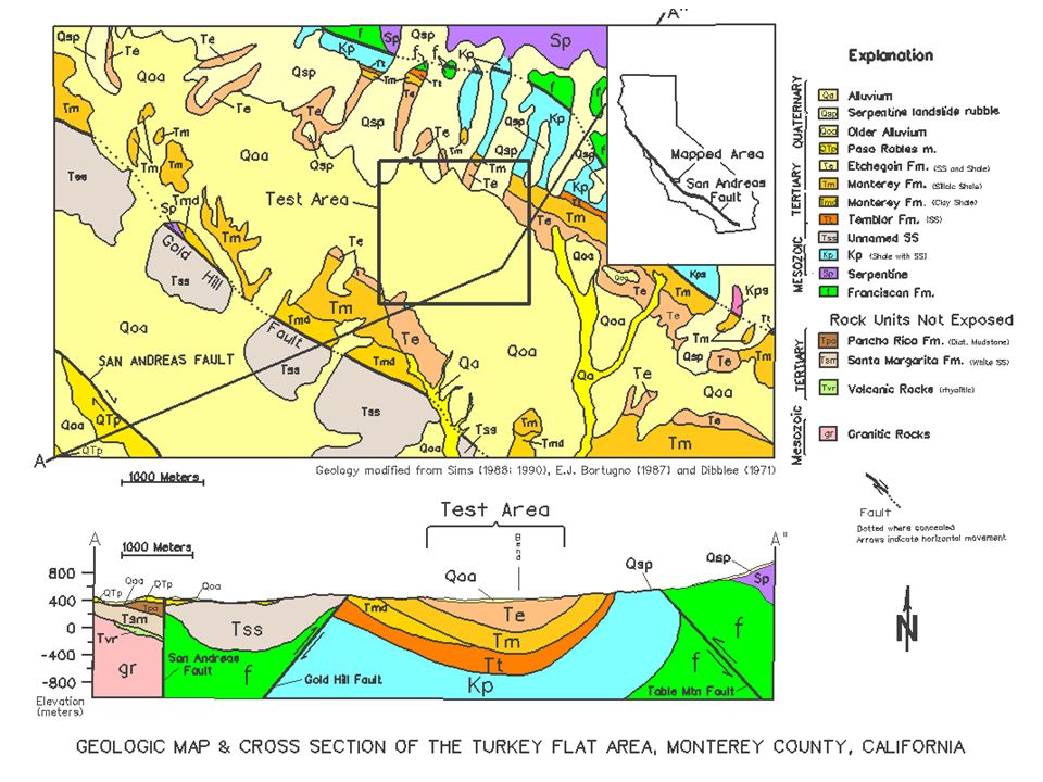
Charles R. Real: California Geological Survey Anthony F. Shakal: California Geological Survey Brian E. Tucker: Geohazards International TURKEY FLAT, U.S.A. SITE EFFECTS TEST AREA: ANATOMY OF A BLIND GROUND-MOTION PREDICTION TEST

2
Need to Validate Ground Motion Prediction Models Theory Data Observation Supposition Hypothesis Measurement Toward Knowledge Experimentation Model Validation Specific Case

3
Background 1985 IASPEI/IAEE Resolution to: –Promote establishment of test sites around world to validate methods of predicting “effects of surface geology on seismic motion” –Form Joint Working Group to provide guidance for establishing test sites 1986 CGS/CSMIP established test site at Turkey Flat near Parkfield, CA

4
Overview Rationale Site Selection/ Characterization Blind Tests Lessons Learned

5
Primary Goals of Turkey Flat Test Help evaluate state-of-practice in site response analysis Create observational database to facilitate site-response research

6
Objectives Validate current ground-motion models for shallow stiff-soil site Understand relative contributions to uncertainty: aleatory/epistemic….ground- motion model and site model Investigate potential non-linear behavior

7
Approach Conduct high-quality field and laboratory tests to characterize the geotechnical properties of the site Collect high-quality measurements of ground response in sediment basin and bordering rock Conduct test that emulates a typical engineering site response application

8
Design Rationale Emulate a common engineering application: –A typical construction site –A forward modeling approach (“blind” test) Simple site / abundant information –Geologically simple –Surface rock records Must have industry participation –Anonymity/confidentiality
 Simple site / abundant information –Geologically simple –Surface rock records Must have industry participation –Anonymity/confidentiality")
9
-Dynamic Soil Properties -Velocity Structure -Site Response = -computational model -Medium model Uncertainty A A – surface rock to basement rock to surface B B – basement rock through soil to surface

10
Understand Uncertainty Statistics: Multiple teams –Site characterization –Site response prediction Isolate two principal modeling steps: –Part A – uncertainty in predicting basement response and how it affects estimated surface response –Part B – uncertainty in predicting soil response given actual basement response Isolate variability due to computational & medium models –Compare results from “preferred” soil models against a control model (“standard”)
")
11
MULTIPLE INVESTIGATION TEAMS SITE CHARACTERIZATION Field Surveys/Borehole logging Laboratory Testing SITE SELECTION SSR Survey Profile Seismic Refraction WEAK-MOTION BLIND TEST 10 Countries 28 Teams PART 1 29 “standard” model predictions 6 “preferred” model predictions PART 2 20 “standard” model predictions 6 “preferred” model predictions ARRAY INSTALLATION Weak-motion (velocity sensors) Strong-motion (accelerometers) 15 Years TURKEY FLAT SITE EFFECTS TEST AREA STRONG-MOTION BLIND TEST 4 Countries 15 Teams PART 1 25 “Standard” model predictions 20 “preferred” model predictions PART 2 25 “standard” model predictions 22 “preferred” model predictions MULTIPLE INVESTIGATION TEAMS
 Strong-motion (accelerometers) 15 Years TURKEY FLAT SITE EFFECTS TEST AREA STRONG-MOTION BLIND TEST 4 Countries 15 Teams PART 1 25 Standard model predictions 20 preferred model predictions PART 2 25 standard model predictions 22 preferred model predictions MULTIPLE INVESTIGATION TEAMS")
12
Experiment Timeline ActivityWhen 1. Site selection & characterization1986 2. Accelerograph Installation1987 3. Weak-motion data collection1988-89 4. Weak-motion prediction test1990 5. Strong-motion data collection? 6. Strong-motion prediction test?

13
Site Selection Criteria A geologically simple site Common site for construction A measurable site effect Strong-motion expected soon

14
1985 Parkfield Earthquake Prediction Experiment (M~6 by 1993)
")
15
Parkfield San Francisco Parkfield Turkey Flat ~2 km D ½W = 1:40

17
View North View South

18
Verification of Site Effect Spectral Ratio Dashed: baseline site Solid: 10m offset Dotted: 20m offset

19
Field Tests

20
Lab Tests

21
Seismic Reflection & Refraction Surveys

22
Cross-sections Through Test Area R1, D1 V1, D2, D3 V2 R2 B B’ A A’ C C’ Next slide shows profiles

24
Experiment Timeline ActivityWhen 1. Geotechnical site characterization1986 2. Accelerograph Installation1987 3. Weak-motion data collection1988-89 4. Weak-motion prediction test1990 5. Strong-motion data collection? 6. Strong-motion prediction test? Accelerographs Installed Weak-motion Data Collection

25
Weak-Motion Test

26
30km M2.0

27
Weak-Motion Test Event

28
Weak Motion Test CountryStandardPreferred Canada 1 1 China 2 Czechoslovakia 2 France 3 1 Germany 1 Italy 1 1 Japan 7 2 Mexico 1 New Zealand 1 USA 6 1 Totals 25 6

29
Weak-Motion Response Spectrum Weak-Motion Response Spectrum Predictions v.s. Observations Solid: Test event Dashed: Prediction Quartiles (Cramer & Real, 1990)
.")
30
Weak-Motion Spectral Ratio Weak-Motion Spectral Ratio Predictions v.s. Observations Solid: Test event Dashed: Prediction quartiles Dot-dash: weak- motion events mean Dotted: 1 of mean (Cramer & Real, 1990)
.")
31
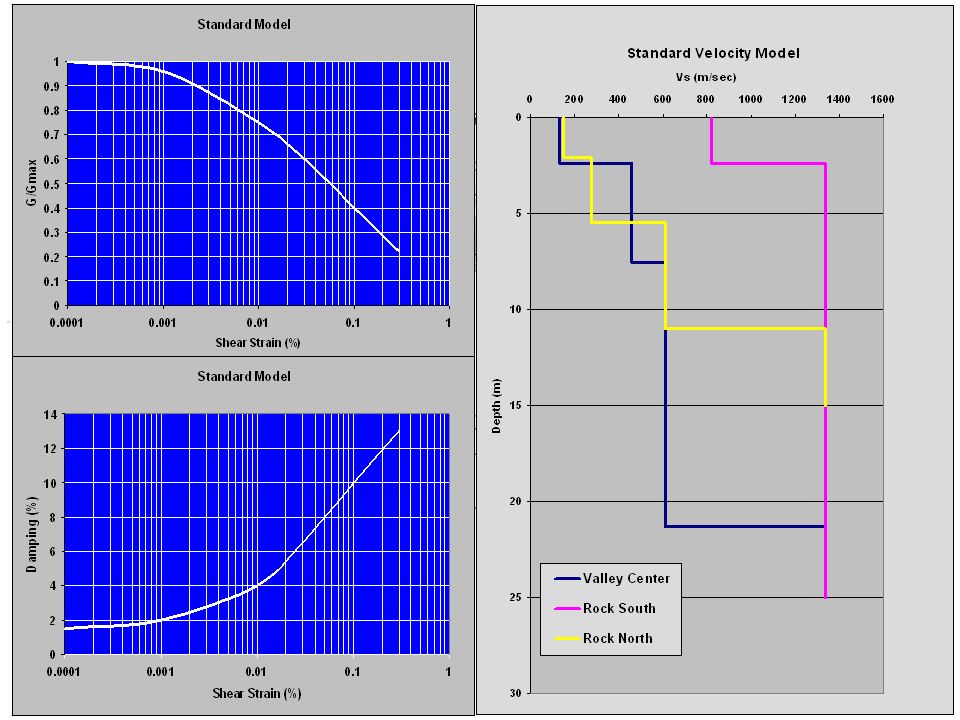
Variability of Velocity Structure Solid: standard model Dashed: Mean Dotted: 2 intervals Dash-dot: 2 of means Bold: median used in simulations (Field & Jacob, 1993)
")
32
Results of Sensitivity Study Results of Sensitivity Study Monte-Carlo Simulations Solid: simulation median Dashed: simulation inter-quartile range Dotted: 90% simulation range Dot-dash: standard model response Bold: median of parameters (Field & Jacob, 1993)
")
33
Insights From Weak-Motion Test Predictions tended to group…generally a success…. Observations fall within range of expected uncertainties from modeling the site data Tendency to over-estimate amplitude… damping too low, velocity of surface layer Participants tended to underestimate uncertainty

34
Strong-Motion Test Timeline ActivityWhen 1. Geotechnical site characterization1986 2. Accelerograph Installation1987 3. Weak-motion data collection1988-89 4. Weak-motion prediction test1990 5. M6.0 Parkfield Earthquake9/28/2004 6. Strong-motion prediction test2005

35
M6.0

36
Test Site

37
Strong Motion Test Event

38
Strong-Motion Test

39
Changes in Blind Test Require predictions based on “preferred” soil model Still have predictions based on “standard” soil model Request more time histories Have two levels of participation: –Volunteer –Funded

40
Required Strong-Motion Predictions Fourier Amplitude Spectral Ratios: –1) X i /R1 given R1 (where X i means D1, D2, D3, V1,V2, R2) –2) V1/D3, D2/D3 given D3 D3 D2 D1 R1 V1 V2 R2 Two-step process: R1 predictions then D3 predictions
 X i /R1 given R1 (where X i means D1, D2, D3, V1,V2, R2) –2) V1/D3, D2/D3 given D3 D3 D2 D1 R1 V1 V2 R2 Two-step process: R1 predictions then D3 predictions")
41
Required Strong-Motion Predictions Acceleration Time Histories: –(1) V1, D2, D3 given R1 –(2) V1, D2 given D3 D3 D2 D1 R1 V1 V2 R2
 V1, D2, D3 given R1 –(2) V1, D2 given D3 D3 D2 D1 R1 V1 V2 R2")
42
Required Strong-Motion Predictions Psuedovelocity Response Spectra (5% damped) & peak values displ, vel, accel: –1) X i given R1 (where X i means D1, D2, D3, V1,V2, R2) –2) V1, D2 given D3 D3 D2 D1 R1 V1 V2 R2
 & peak values displ, vel, accel: –1) X i given R1 (where X i means D1, D2, D3, V1,V2, R2) –2) V1, D2 given D3 D3 D2 D1 R1 V1 V2 R2")
43
Strong-Motion Prediction Teams Italy1 Japan4 Republic of Czechoslovakia1 United States9 TotalParticipants 15

44
82 Sector Part 1 Part 2 Total PreferredStandardPreferredStandard Industry 545418 Academia 1511171154 Government 505010 Strong-Motion Prediction Sets Industry 18

45
1-D Methods Method/Code No. Sets Category No. Predictions 1 Part 1Part 2 SHAKE042Equivalent Linear04 SHAKE96B4Equivalent Linear124 SHAKE918Equivalent Linear2411 SHAKE724Equivalent Linear1210 TremorKA2Equivalent Linear62 TremorN22Equivalent Linear62 DeepSoil12Equivalent Linear/Nonlinear2412 FDM4Equivalent Linear126 DMOD-26Nonlinear Finite Element410 RASCAL4Equivalent Linear124 TESS4Nonlinear Finite Difference74 PEXT2Linear Full Wave Propagation66 Freq/Wavenmbr1Equivalent Linear60 DYNEQ4Equivalent Linear94 Subtotal(59)Subtotal(140)(79)
Subtotal(140)(79).")
46
2-D/3-D Methods Method/Code No. Sets Category No. Predictions Part 1Part 2 2-D NOAHW2Nonlinear Finite Difference62 BESOIL2Equivalent Linear62 SuperFLUSH2 Equivalent-Linear Finite Element 62 Subtotal(6)Subtotal(18)(6) 3-D FLAC5Nonlinear Finite Difference46 OpenSees4Nonlinear Finite Element54 SUMDES4Nonlinear Finite Element44 Subtotal(13)Subtotal(13)(14) Empirical SSR2Empirical65 Subtotal(2)Subtotal(6)(5) Total 1,2 &3-D80 2 Total177104 2 Two additional prediction sets from averaging several codes
Subtotal(18)(6) 3-D FLAC5Nonlinear Finite Difference46 OpenSees4Nonlinear Finite Element54 SUMDES4Nonlinear Finite Element44 Subtotal(13)Subtotal(13)(14) Empirical SSR2Empirical65 Subtotal(2)Subtotal(6)(5) Total 1,2 &3-D80 2 Total Two additional prediction sets from averaging several codes.")
47
Workshop Timeline WhereWhen 1. Vancouver, B.C.1987 2. Tokyo, Japan1992 3. San Francisco, CA September 21, 2006

48
Turkey Flat Workshop (September 21, 2006) Release observations at workshop Overview of observations/predictions –Predictions identified by team number only Expert panels: –Equivalent-linear methods –Nonlinear methods –Site Characterization
 Release observations at workshop Overview of observations/predictions –Predictions identified by team number only Expert panels: –Equivalent-linear methods –Nonlinear methods –Site Characterization")
49
Lessons Learned More redundancy in site characterization Increase participation Require “standard” & “preferred” models Flexible submission formats

50
Potential Issues Considering proximity of Turkey Flat array to source rupture could observed motions be affected by finite source effects? Circa 1990 State-of-practice in site characterization?

51
Turkey Flat Working Group www.quake.ca.gov/turkeyflat.htm Individuals Carl Stepp C.Y. Chang Neville Donovan James Gates I.M. Idriss Fumio Kaneko Marshall Lew Saturo Ohya Maurice Power Bruce Redpath Wolfgang Roth J.P. Singh John Vrymoed William Joyner Bill Iwan Kazuyoshi Kudo P.Y. Bard Jon Stewart Brian Chiou Chris Cramer Abbas Abghari Ben Tsai Steve Kramer Ahmad Elgamal Youssef Hashash Geoff Martin Yousef Borgzonia Companies Dames and Moore Harding Lawson and Associates Kajima Corporation Lawrence Livermore National Laboratory LeRoy Crandall and Associates OYO Corporation Pitcher Drilling Qest Consultants Woodward-Clyde Consultants Land Owners – Donald and Nila McCornack

Similar presentations


 USING COMPONENT ATTENUATION MODELLING TECHNIQUE By DR. SAROSH.H. LODI.>")


>")