Download presentation
Presentation is loading. Please wait.

1
Lecture 17: Storage and I/O EEN 312: Processors: Hardware, Software, and Interfacing Department of Electrical and Computer Engineering Spring 2014, Dr. Rozier (UM)
.")
2
I/O AND BUSES

3
Bus Types Processor-Memory buses – Short, high speed – Design is matched to memory organization I/O buses – Longer, allowing multiple connections – Specified by standards for interoperability – Connect to processor-memory bus through a bridge

4
Bus Signals and Synchronization Data lines – Carry address and data – Multiplexed or separate Control lines – Indicate data type, synchronize transactions Synchronous – Uses a bus clock Asynchronous – Uses request/acknowledge control lines for handshaking

5
I/O Bus Examples FirewireUSB 2.0PCI ExpressSerial ATASerial Attached SCSI Intended useExternal Internal External Devices per channel 63127114 Data width422/lane44 Peak bandwidth 50MB/s or 100MB/s 0.2MB/s, 1.5MB/s, or 60MB/s 250MB/s/lane 1×, 2×, 4×, 8×, 16×, 32× 300MB/s Hot pluggable Yes DependsYes Max length4.5m5m0.5m1m8m StandardIEEE 1394USB Implementers Forum PCI-SIGSATA-IOINCITS TC T10

6
Typical x86 PC I/O System

7
I/O Management I/O is mediated by the OS – Multiple programs share I/O resources Need protection and scheduling – I/O causes asynchronous interrupts Same mechanism as exceptions – I/O programming is fiddly OS provides abstractions to programs

8
I/O Commands I/O devices are managed by I/O controller hardware – Transfers data to/from device – Synchronizes operations with software Command registers – Cause device to do something Status registers – Indicate what the device is doing and occurrence of errors Data registers – Write: transfer data to a device – Read: transfer data from a device

9
I/O Register Mapping Memory mapped I/O – Registers are addressed in same space as memory – Address decoder distinguishes between them – OS uses address translation mechanism to make them only accessible to kernel I/O instructions – Separate instructions to access I/O registers – Can only be executed in kernel mode – Example: x86

10
Polling Periodically check I/O status register – If device ready, do operation – If error, take action Common in small or low-performance real- time embedded systems – Predictable timing – Low hardware cost In other systems, wastes CPU time

11
Interrupts When a device is ready or error occurs – Controller interrupts CPU Interrupt is like an exception – But not synchronized to instruction execution – Can invoke handler between instructions – Cause information often identifies the interrupting device Priority interrupts – Devices needing more urgent attention get higher priority – Can interrupt handler for a lower priority interrupt

12
Interrupts vs. Polling Which is better? Why? Break into groups

13
I/O Data Transfer Polling and interrupt-driven I/O – CPU transfers data between memory and I/O data registers – Time consuming for high-speed devices Direct memory access (DMA) – OS provides starting address in memory – I/O controller transfers to/from memory autonomously – Controller interrupts on completion or error
 – OS provides starting address in memory – I/O controller transfers to/from memory autonomously – Controller interrupts on completion or error")
14
DMA/Cache Interaction If DMA writes to a memory block that is cached – Cached copy becomes stale If write-back cache has dirty block, and DMA reads memory block – Reads stale data Need to ensure cache coherence – Flush blocks from cache if they will be used for DMA – Or use non-cacheable memory locations for I/O

15
DMA/VM Interaction OS uses virtual addresses for memory – DMA blocks may not be contiguous in physical memory Should DMA use virtual addresses? – Would require controller to do translation If DMA uses physical addresses – May need to break transfers into page-sized chunks – Or chain multiple transfers – Or allocate contiguous physical pages for DMA

16
PERFORMANCE

17
Measuring I/O Performance I/O performance depends on – Hardware: CPU, memory, controllers, buses – Software: operating system, database management system, application – Workload: request rates and patterns I/O system design can trade-off between response time and throughput – Measurements of throughput often done with constrained response-time

18
Transaction Processing Benchmarks Transactions – Small data accesses to a DBMS – Interested in I/O rate, not data rate Measure throughput – Subject to response time limits and failure handling – ACID (Atomicity, Consistency, Isolation, Durability) – Overall cost per transaction Transaction Processing Council (TPC) benchmarks (www.tcp.org) – TPC-APP: B2B application server and web services – TCP-C: on-line order entry environment – TCP-E: on-line transaction processing for brokerage firm – TPC-H: decision support — business oriented ad-hoc queries
 – Overall cost per transaction Transaction Processing Council (TPC) benchmarks ( – TPC-APP: B2B application server and web services – TCP-C: on-line order entry environment – TCP-E: on-line transaction processing for brokerage firm – TPC-H: decision support — business oriented ad-hoc queries")
19
File System & Web Benchmarks SPEC System File System (SFS) – Synthetic workload for NFS server, based on monitoring real systems – Results Throughput (operations/sec) Response time (average ms/operation) SPEC Web Server benchmark – Measures simultaneous user sessions, subject to required throughput/session – Three workloads: Banking, Ecommerce, and Support
 – Synthetic workload for NFS server, based on monitoring real systems – Results Throughput (operations/sec) Response time (average ms/operation) SPEC Web Server benchmark – Measures simultaneous user sessions, subject to required throughput/session – Three workloads: Banking, Ecommerce, and Support")
20
Amdahl’s Law What was it again? Getting back to Chapter 1…

21
I/O vs. CPU Performance Amdahl’s Law – Don’t neglect I/O performance as parallelism increases compute performance Example – Benchmark takes 90s CPU time, 10s I/O time – Double the number of CPUs/2 years I/O unchanged YearCPU timeI/O timeElapsed time% I/O time now90s10s100s10% +245s10s55s18% +423s10s33s31% +611s10s21s47%

22
RELIABILITY

23
RAID Redundant Array of Inexpensive (Independent) Disks – Use multiple smaller disks (c.f. one large disk) – Parallelism improves performance – Plus extra disk(s) for redundant data storage Provides fault tolerant storage system – Especially if failed disks can be “hot swapped”
 – Parallelism improves performance – Plus extra disk(s) for redundant data storage Provides fault tolerant storage system – Especially if failed disks can be hot swapped .")
24
RAID 0 – No redundancy (“AID”?) – Doesn’t help with reliability, but does improve performance. How does it improve performance?

25
RAID 1 – Mirroring – Improves performance and reliability! – High overhead cost! How much?

26
RAID 2 Striped at bit level – Uses Hamming codes for reliability – To complex in practice – Not used often

27
Hamming Codes A way to detect errors

28
Hamming Codes Take the data and G Compute the product modulo 2 Data Result

29
Hamming Codes A way to detect errors

30
Hamming Codes A way to detect errors

31
Hamming Codes d0 = 0 d1 = 1 d2 = 1 d3 = 1 What are p1, p2, and p3?

32
RAID 3 An easier way to do correction Byte level striping Parity is XOR parity Disks spin in lock-step for easy striping Not used in practice due to lock-step req.

33
RAID 4 Block interleaved parity Parity computed as XOR of blocks

34
RAID 4 Given the following 4-bit blocks, what is the parity? 1011 1111 0001

35
RAID 4 How to rebuild? 1011 XXXX 0001 P: 0101

36
RAID 5

37
Why is this better than RAID 4?

38
RAID 6 Adds additional Q redundancy. Requires additional syndrome computation

39
Galois Field Algebra Galois Field – also called a “finite field” – Contains a finite number of elements called it’s size.

40
Galois Field Algebra Introduce some new Galois field GF(m) For each block of data, we chose a corresponding element of the Galois field New syndrome is independent.
 For each block of data, we chose a corresponding element of the Galois field New syndrome is independent.")
41
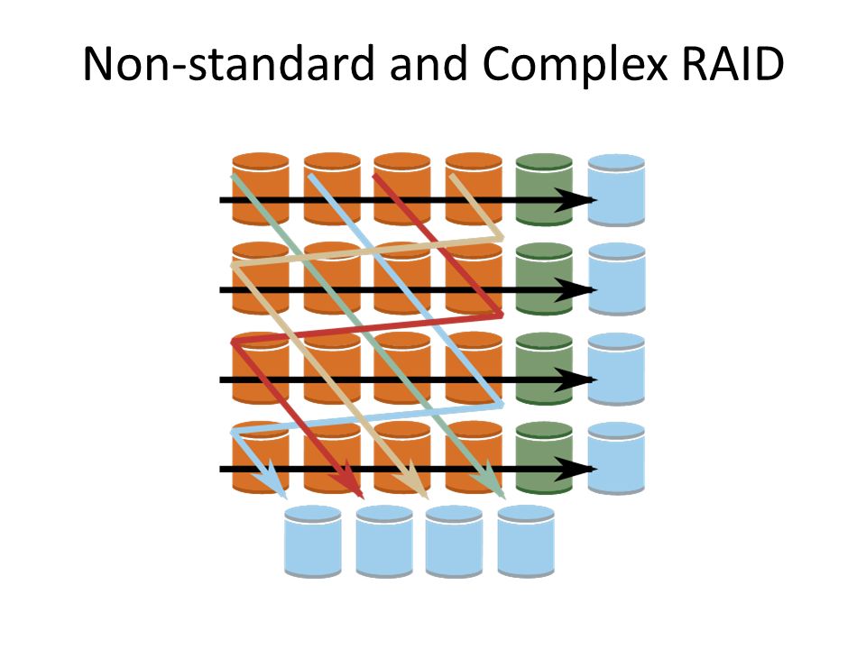
Non-standard and Complex RAID

43
RAID Summary RAID can improve performance and availability – High availability requires hot swapping Assumes independent disk failures – Too bad if the building burns down! See “Hard Disk Performance, Quality and Reliability ” – http://www.pcguide.com/ref/hdd/perf/index.htm

44
I/O System Design Satisfying latency requirements – For time-critical operations – If system is unloaded Add up latency of components Maximizing throughput – Find “weakest link” (lowest-bandwidth component) – Configure to operate at its maximum bandwidth – Balance remaining components in the system If system is loaded, simple analysis is insufficient – Need to use queuing models or simulation
 – Configure to operate at its maximum bandwidth – Balance remaining components in the system If system is loaded, simple analysis is insufficient – Need to use queuing models or simulation")
45
Next week How processors are manufactured Course synthesis

Similar presentations

 and –Availability.>")
 Disks –Use multiple smaller disks (c.f. one large disk)>")

Explain the limitations of flash memory. 2)Define wear leveling. 3)Define the term IO Transaction 4)Define the terms synchronous.>")


 Performance: — access latency — throughput — connection.>")


 Disks Use multiple smaller disks (c.f.>")


