Download presentation
Presentation is loading. Please wait.

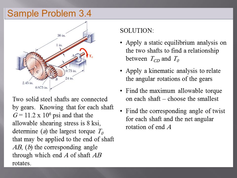
3
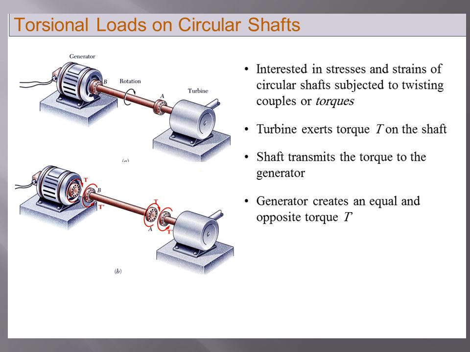
Suitability of a structure or machine may depend on the deformations in the structure as well as the stresses induced under loading. Statics analyses alone are not sufficient. Considering structures as deformable allows determination of member forces and reactions which are statically indeterminate. Determination of the stress distribution within a member also requires consideration of deformations in the member. Chapter 2 is concerned with deformation of a structural member under axial loading. Later chapters will deal with torsional and pure bending loads.

8
Below the yield stress Strength is affected by alloying, heat treating, and manufacturing process but stiffness (Modulus of Elasticity) is not.
 is not.")
9
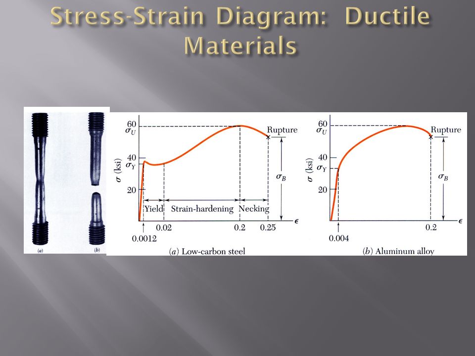
If the strain disappears when the stress is removed, the material is said to behave elastically. When the strain does not return to zero after the stress is removed, the material is said to behave plastically. The largest stress for which this occurs is called the elastic limit.

10
Fatigue properties are shown on S-N diagrams. When the stress is reduced below the endurance limit, fatigue failures do not occur for any number of cycles. A member may fail due to fatigue at stress levels significantly below the ultimate strength if subjected to many loading cycles.

11
From Hooke’s Law: From the definition of strain: Equating and solving for the deformation, With variations in loading, cross-section or material properties,

12
Determine the deformation of the steel rod shown under the given loads. SOLUTION: Divide the rod into components at the load application points. Apply a free-body analysis on each component to determine the internal force Evaluate the total of the component deflections.

13
SOLUTION: Divide the rod into three components: Apply free-body analysis to each component to determine internal forces, Evaluate total deflection,

14
The rigid bar BDE is supported by two links AB and CD. Link AB is made of aluminum ( E = 70 GPa) and has a cross-sectional area of 500 mm 2. Link CD is made of steel ( E = 200 GPa) and has a cross-sectional area of (600 mm 2 ). For the 30-kN force shown, determine the deflection a) of B, b) of D, and c) of E. SOLUTION: Apply a free-body analysis to the bar BDE to find the forces exerted by links AB and DC. Evaluate the deformation of links AB and DC or the displacements of B and D. Work out the geometry to find the deflection at E given the deflections at B and D.
 and has a cross-sectional area of 500 mm 2. Link CD is made of steel ( E = 200 GPa) and has a cross-sectional area of (600 mm 2 ). For the 30-kN force shown, determine the deflection a) of B, b) of D, and c) of E. SOLUTION: Apply a free-body analysis to the bar BDE to find the forces exerted by links AB and DC. Evaluate the deformation of links AB and DC or the displacements of B and D. Work out the geometry to find the deflection at E given the deflections at B and D..")
15
Displacement of B : Displacement of D : Free body: Bar BDE SOLUTION: Sample Problem 2.1

16
Displacement of D: Sample Problem 2.1

17
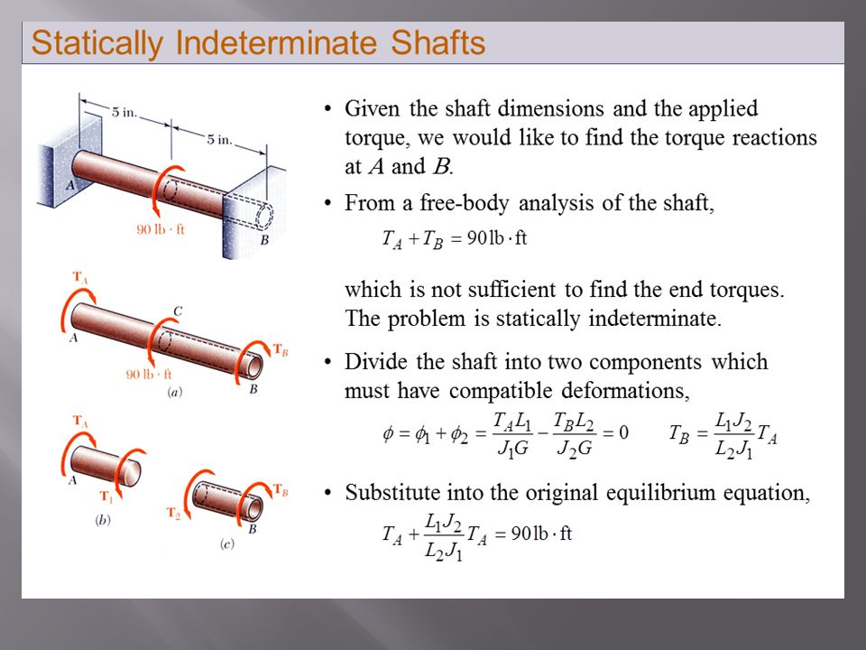
Structures for which internal forces and reactions cannot be determined from statics alone are said to be statically indeterminate. Deformations due to actual loads and redundant reactions are determined separately and then added or superposed. Redundant reactions are replaced with unknown loads which along with the other loads must produce compatible deformations. A structure will be statically indeterminate whenever it is held by more supports than are required to maintain its equilibrium.

18
Determine the reactions at A and B for the steel bar and loading shown, assuming a close fit at both supports before the loads are applied. Solve for the reaction at A due to applied loads and the reaction found at B. Require that the displacements due to the loads and due to the redundant reaction be compatible, i.e., require that their sum be zero. Solve for the displacement at B due to the redundant reaction at B. SOLUTION: Consider the reaction at B as redundant, release the bar from that support, and solve for the displacement at B due to the applied loads.

19
SOLUTION: Solve for the displacement at B due to the applied loads with the redundant constraint released, Solve for the displacement at B due to the redundant constraint, Example 2.04

20
Require that the displacements due to the loads and due to the redundant reaction be compatible, Find the reaction at A due to the loads and the reaction at B Example 2.04

21
A temperature change results in a change in length or thermal strain. There is no stress associated with the thermal strain unless the elongation is restrained by the supports. Treat the additional support as redundant and apply the principle of superposition. The thermal deformation and the deformation from the redundant support must be compatible.

22
For a slender bar subjected to axial loading: The elongation in the x-direction is accompanied by a contraction in the other directions. Assuming that the material is isotropic (no directional dependence), Poisson’s ratio is defined as
, Poisson’s ratio is defined as.")
23
For an element subjected to multi-axial loading, the normal strain components resulting from the stress components may be determined from the principle of superposition. This requires: 1)strain is linearly related to stress 2)deformations are small With these restrictions:
strain is linearly related to stress 2)deformations are small With these restrictions:.")
24
Relative to the unstressed state, the change in volume is For element subjected to uniform hydrostatic pressure, Subjected to uniform pressure, dilatation must be negative, therefore

25
A cubic element subjected to a shear stress will deform into a rhomboid. The corresponding shear strain is quantified in terms of the change in angle between the sides, A plot of shear stress vs. shear strain is similar the previous plots of normal stress vs. normal strain except that the strength values are approximately half. For small strains, where G is the modulus of rigidity or shear modulus.

26
A rectangular block of material with modulus of rigidity G = 90 ksi is bonded to two rigid horizontal plates. The lower plate is fixed, while the upper plate is subjected to a horizontal force P. Knowing that the upper plate moves through 0.04 in. under the action of the force, determine a) the average shearing strain in the material, and b) the force P exerted on the plate. SOLUTION: Determine the average angular deformation or shearing strain of the block. Use the definition of shearing stress to find the force P. Apply Hooke’s law for shearing stress and strain to find the corresponding shearing stress.
 the average shearing strain in the material, and b) the force P exerted on the plate. SOLUTION: Determine the average angular deformation or shearing strain of the block. Use the definition of shearing stress to find the force P. Apply Hooke’s law for shearing stress and strain to find the corresponding shearing stress..")
27
Determine the average angular deformation or shearing strain of the block. Apply Hooke’s law for shearing stress and strain to find the corresponding shearing stress. Use the definition of shearing stress to find the force P.

28
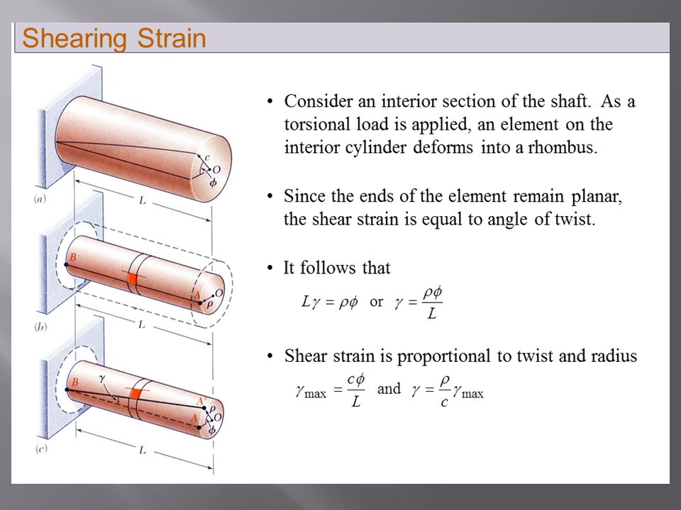
An axially loaded slender bar will elongate in the axial direction and contract in the transverse directions. Components of normal and shear strain are related, If the cubic element is oriented as in the bottom figure, it will deform into a rhombus. Axial load also results in a shear strain. An initially cubic element oriented as in top figure will deform into a rectangular parallelepiped. The axial load produces a normal strain.

29
A circle of diameter d = 9 in. is scribed on an unstressed aluminum plate of thickness t = 3/4 in. Forces acting in the plane of the plate later cause normal stresses x = 12 ksi and z = 20 ksi. For E = 10x10 6 psi and = 1/3, determine the change in: a)the length of diameter AB, b)the length of diameter CD, c)the thickness of the plate, and d)the volume of the plate.
the length of diameter AB, b)the length of diameter CD, c)the thickness of the plate, and d)the volume of the plate..")
30
SOLUTION: Apply the generalized Hooke’s Law to find the three components of normal strain. Evaluate the deformation components. Find the change in volume

31
Fiber-reinforced composite materials are formed from lamina of fibers of graphite, glass, or polymers embedded in a resin matrix. Normal stresses and strains are related by Hooke’s Law but with directionally dependent moduli of elasticity, Transverse contractions are related by directionally dependent values of Poisson’s ratio, e.g., Materials with directionally dependent mechanical properties are anisotropic.

32
Loads transmitted through rigid plates result in uniform distribution of stress and strain. Saint-Venant’s Principle: Stress distribution may be assumed independent of the mode of load application except in the immediate vicinity of load application points. Stress and strain distributions become uniform at a relatively short distance from the load application points. Concentrated loads result in large stresses in the vicinity of the load application point.

33
When a single structural element is loaded uniformly beyond its yield stress and then unloaded, it is permanently deformed but all stresses disappear. This is not the general result. Residual stresses also result from the uneven heating or cooling of structures or structural elements Residual stresses will remain in a structure after loading and unloading if -only part of the structure undergoes plastic deformation -different parts of the structure undergo different plastic deformations

34
A cylindrical rod is placed inside a tube of the same length. The ends of the rod and tube are attached to a rigid support on one side and a rigid plate on the other. The load on the rod-tube assembly is increased from zero to 5.7 kips and decreased back to zero. a)draw a load-deflection diagram for the rod-tube assembly b)determine the maximum elongation c)determine the permanent set d)calculate the residual stresses in the rod and tube.
draw a load-deflection diagram for the rod-tube assembly b)determine the maximum elongation c)determine the permanent set d)calculate the residual stresses in the rod and tube..")
Similar presentations


>")


