Download presentation
Presentation is loading. Please wait.

1
Software Engineering Data flow diagrams

2
Using Data Flow Diagrams

3
Theory Data is your main player Your must have the right tool box
Data will start at a source Data will end at a sink Data will change at a process Data will be stored or retrieved at a data store Your must have the right tool box GRAMMER is your camera Balance is the rule of thump Abstract diagram Rules and restrictions

5
Advantages of DFD Freedom from involving with technical implementation too early Provide information inter-relatedness of systems and sub-systems Can be used as a tool for communicating with users (but, users must have some knowledge about the DFD) Analysis of a proposed system to determine all important data and process have been defined
 Analysis of a proposed system to determine all important data and process have been defined.")
6
Four Basic Symbols Used in DFD
Entity is considered as EXTERNAL to the system e.g., a department, a person, or a business should be named with a “noun” can be used more than once in order to avoid crossing Data Flow shows movement of data each arrow represents only one data flow

7
Four Basic Symbols Used in DFD
Process represents a process should use verb-adjective-noun format for naming all processes e.g., “Add Inventory Record” must record also have unique number which represent each process and indicate its level Data may represent database or filing cabinet should be named with a “noun” Note: temporary data stores, scratch paper, or temporary computer files are not included

8
Process for Developing DFD
Make a list of business activities and use it to determine: External entities Data Flows Processes Data Stores Draw a Context diagram which shows only a single process (represent the entire system), and external entities Draw a Diagram-0 (Level-0 diagram) shows general processes shows data stores Draw child diagrams (Level-1 diagram) for each of the process in Diagram-0
, and external entities. Draw a Diagram-0 (Level-0 diagram) shows general processes. shows data stores. Draw child diagrams (Level-1 diagram) for each of the process in Diagram-0.")
9
Process for Developing DFD
Check for errors and all labels to ensure that they are meaningful (ref. Fig 9.4, 9.5, and 9.6) Develop physical data flow diagram from the logical data flow Distinguish between manual & automated processes Describe actual files & reports by name Add controls to indicate when error occur Partition the physical data flow diagram by grouping parts of the diagram from implementation purpose
 Develop physical data flow diagram from the logical data flow. Distinguish between manual & automated processes. Describe actual files & reports by name. Add controls to indicate when error occur. Partition the physical data flow diagram by grouping parts of the diagram from implementation purpose.")
10
Logical vs Physical DFD
Logical diagrams: show how the business operates, not how the system will be implemented describe each event and data required Physical diagrams: show how the system will be implemented e.g., details about hardware, software, files and people involved (Figure 9.10)
")
11
Characteristics of Physical DFD
Determine manual or automated processes Provide more details than logical DFD Sequence processes that have to be done in a particular order Identify temporary file(s) required Use actual names of files and printouts
 required. Use actual names of files and printouts.")
12
Partitioning DFD Analyzing each process to determine whether it should be a manual or automated process Reasons for partitioning Different user groups: Different group of users may work on different set of data which require different interface Efficiency: Several batch processes may be combined into one program to save time required Security: Some process (program) is only for a certain group
 is only for a certain group.")
29
System contexts The boundaries of the system must be established to determine what must be implemented These are documented using a description of the system context. This should include a description of the other systems which are in the environment Social and organizational factors may influence the positioning of the system boundary

30
Auto-teller system context

35
Online Order processing problem statement
Each on-line order is processed for release to the manufacturing floor. Release is generally dependent upon approval of the designated form of payment. Credit card orders move faster while orders paid by other methods generally take longer. Once payment is confirmed, the order will be released for production. The order is then sent to the company distributor of UIGC corporation, items . Once received by the distribution facility, the order will be prepared and released for shipping. Delivery prep is normally completed within one day of the date production is complete. However, larger orders and orders requiring special handling and refrigerating may take longer. Each order is shipped and will be in route to its ship-to destination as of the "Ship Date" that is indicated. Delivery time varies based on the shipping option chosen at the time of order entry. Each order will generally reach its intended destination within business days of the "Ship Date" noted

36
1- Smartly Identify different grammatical types in sentences
Each on-line order is processed for release to the manufacturing floor. Release is generally dependent upon approval of the designated form of payment. Credit card orders move faster while orders paid by other methods generally take longer. Once payment is confirmed, the order will be released for production. The order is then sent to the company distributor of UIGC corporation items . Once received by the distribution facility, the order will be prepared and released for shipping. Delivery prep is normally completed within one day of the date production is complete. However, larger orders and orders requiring special handling and refrigerating may take longer. Each order is shipped and will be in route to its ship-to destination as of the "Ship Date" that is indicated. Delivery time varies based on the shipping option chosen at the time of order entry. Each order will generally reach its intended destination within business days of the "Shipping”.

37
Build the analytical table:
Sentence # Nouns Analysis Verbs 1 Online order Sub-class Sub –system Data flow Process Release Manufacture Process,Ass. Process,Ass 2 Payment Super-Class ERM Entity Approve Designate 3 Credit card Order Confirm Produce 4 Company distributor UIGC External entity Send 5 Distribution facility Receive Prepare Ship 6 Deliver complete 7 Large order Require Refrigerate Handle Pro, Ass. Process,Ass. 8 Ship-date Destination Attribute Class Route Indicate 9 Choose Enter data 10 Intended destination Reach

40
*

41
More Examples on Data Flow Diagrams

42
Data Flow Diagram (DFD)
It is designed to show how a system is divided into smaller portions, and to highlight the flow of data between those parts.

43
Context-Level Data Flow Diagram Showing Project Scope for Purchasing Fulfillment System

44
Comparison of DeMarco & Yourdan and Gane & Sarson DFD Symbol Sets

45
Differences between Sources/Sinks and Processes
(a) Improperly Drawn DFD
 Improperly Drawn DFD.")
46
Differences between Sources/Sinks and Processes
(b) Proper Use of a Process
 Proper Use of a Process.")
47
Context Diagram of Hoosier Burger’s Food Ordering System

48
Level-0 DFD of Hoosier Burger’s Food Ordering System

49
Level-1 Diagram Showing Decomposition of Process 1
Level-1 Diagram Showing Decomposition of Process 1.0 from the Level-0 Diagram

50
Level-1 Diagram Showing the Decomposition of Process 4
Level-1 Diagram Showing the Decomposition of Process 4.0 from the Level-0 Diagram

51
Level-2 Diagram Showing the Decomposition of Process 4
Level-2 Diagram Showing the Decomposition of Process 4.3 from the Level-1 Diagram for Process 4.0

52
Hoosier Burger’s Current Physical Inventory Control
(a) Context Diagram
 Context Diagram.")
53
Hoosier Burger’s Current Physical Inventory Control System
(b) Level-0 Data Flow Diagram
 Level-0 Data Flow Diagram.")
54
Level-0 Data Flow Diagram for Hoosier Burger’s Current Logical Inventory Control System

55
Level-0 Flow Diagram for Hoosier Burger’s New Logical Inventory Control System

56
Hoosier Burger’s Hiring Procedures

57
Repository Entry for a Data Flow Diagram

58
IBM Credit Corporation’s Primary Work Process before BPR

59
IBM Credit Corporation’s Primary Work Process after BPR

60
Current Logical DFD for Hoosier Burger’s Inventory Control System

61
Practice Activity Problem&Solution

62
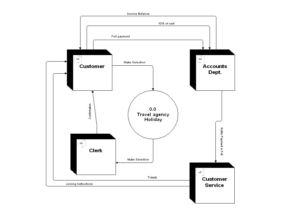
Travel Agency A travel agency arranges holidays for customers. Bookings are made directly by customers. When a customer makes an approach, the reservations clerk selects appropriate flight details and hotel details from lists which are regularly updated. The details are entered onto a Provisional Booking file. The customer must confirm this booking within three days by sending a deposit of 10% of the costs. On receipt of the deposit, Reservations transfer the details from the Provisional Bookings file to the Full Bookings file. Four weeks before the flight is due, Accounts send an invoice to the customer for the remaining costs. Accounts notify Customer services when the full payment is received, and Customer Services then send tickets and joining instructions to the customer.

63
Look for nouns and verbs in a data mining approach
1- Identify nouns and verbs generally 2- Allocate significant nouns and verbs by Extracting those who play one of data flaw diagrams 4 roles 3-Eliminate: Redundant , Irrelevant components plus internal entities 4- Explore domain and add more significant components 5- Assign significant components to notations 6- Connect notations 7- Review and modify ( Do until satisfied)
")
64
Travel Agency A travel agency arranges holidays for customers. Bookings are made directly by customers. When a customer makes an approach, the reservations clerk selects appropriate flight details and hotel details from lists which are regularly updated. The details are entered onto a Provisional Booking file. The customer must confirm this booking within three days by sending a deposit of 10% of the costs. On receipt of the deposit, Reservations transfer the details from the Provisional Bookings file to the Full Bookings file. Four weeks before the flight is due, Accounts send an invoice to the customer for the remaining costs. Accounts notify Customer services when the full payment is received, and Customer Services then send tickets and joining instructions to the customer.

65
Line Number Grammatical analysis (Noun, Verb) Allocation
2 Customers External Entity 3 Reservation Clerk ,Select ,Flight details , hotel details , lists Internal Entity,Process,flaw,flaw, Data store 4 Updated Data store (Internal) 5 Entered Provisional booking file Process 6 Confirm ,Send ,Deposit Process,Process, output flaw 7 Reservations, transfer, provisional bookings file Internal entity,process,data store 8 Full booking file 9 Accounts , send, Invoice Internal entity, process, data flaw 10 Notify 11 Customer services, full payment ,received Internal entity, data flaw , process I2 Send, Tickets, Instructions Process,flaw,flaw
 5. Entered. Provisional booking file. Process. 6. Confirm ,Send ,Deposit. Process,Process, output flaw. 7. Reservations, transfer, provisional bookings file. Internal entity,process,data store. 8. Full booking file. 9. Accounts , send, Invoice. Internal entity, process, data flaw. 10. Notify. 11. Customer services, full payment ,received. Internal entity, data flaw , process. I2. Send, Tickets, Instructions. Process,flaw,flaw.")
66
Hotel list +Flight list Provisional Booking file
External entities Customer Processes Enter Confirm Send1 ,Send2 ,Send3 Received Notify Data stores Lists : Hotel list +Flight list Provisional Booking file Full booking file Data flaws Flight details Hotel details Deposit Invoice Ticket Instructions

67
Re-Wording processes to maintain uniqueness By bottom-up thinking ,
we can group four processes into two and leave The rest as they are : Send 1 + Enter = Make initial booking Confirm= Confirm Booking Send 2 = Bill customer Receive + notify = Receive payments Send 3 = Send Tickets We will end up with five processes in leve1 DFD

70
Some Students’ Approaches

71
DFD for Travel Agency Main Service
Flight Details Hotel Details TBF 1.2 Enter Details 1.1 Make Selection 1.5 Send Invoice Accounts Customer Reservation Clerk 1.3 Sends Deposit/Confirms Reservation 1.3 Sends Deposit / Confirms Reservation 1.7 Send Tickets & Joining Instructions 1.6 Notify Payment 1.4 Transfer Details Customer Service FBF

72
DFD for Travel Agency Main Service
Flight / Hotel Details Temp Booking Files 1.2 Enter Details 1.1 Make Selection 1.5 Send Invoice Accounts Customer Reservation Clerk 1.3 Confirms Reservation 1.7 Send Tickets & Joining Instructions 1.6 Notify Payment 1.4 Transfer Details Customer Service Final Booking Files

75
Elements and Definitions
STRUCTURE CHARTS Elements and Definitions

77
Software System Design
translates SRS into a ===> software system architecture: system’s static structure system’s possible dynamic behaviour data structures user interface design

78
Structured Analysis and Design
prepare and analyse a Data Flow Diagram - DFD derive from the DFD a Structure Chart

79
Structure Chart supports the system and module design phase
diagramming technique with annotations hierarchy of modules control (invocation) is explicitly modelled data flows follow control hierarchy decomposition is shown in the control hierarchy software / computer oriented derived from the DFD and further refined
 is explicitly modelled. data flows follow control hierarchy. decomposition is shown in the control hierarchy. software / computer oriented. derived from the DFD and further refined.")
80
System Structure - Control Hierarchy

81
Complete SC Design Structure Chart Diagram Data Dictionary (e.g. BNF)
Module Specifications (e.g. PDL) ===> consistent with DFD!
 ===> consistent with DFD!")
82
Structure Charts - Module
process / subroutine / task unit of execution accepts parameters as inputs produces parameters as outputs parameters: data or control can be invoked and can invoke label: verb linked to module specification label

83
TRANSFORM ANALYSIS Heuristics and Rules

84
center of transformation
DFD with Transform Flow Characteristics input-driven center of transformation output-driven

85
Structured Analysis and Design Information Flow Analysis
1 - specify the flow of information in your system => DFD 2 - identify typical structural patterns in the DFD => analysed & annotated DFD 3 - use a proven heuristic to map DFD into SC => first SC 4 - refine and check your Structure Chart => final SC

86
Transform Analysis - Step 1
the DFD should exist as a result of systems requirements engineering and systems analysis check completeness of the DFD, data dictionary, and process dictionary refine the DFD (decompose, etc.) if that is necessary
 if that is necessary.")
87
printer user invoice prepare invoice print invoice invoice_prt registration reg+ reg-profile read & check reg. prices registration db conf_msg reg_info reg+ write conf. error_msg accept reg. conf. user

88
registration reg+ read registration reg_i check registration reg+ error_reason error-handler registration error_msg

89
Transform Analysis - Step 2
Step 2a: check the list of properties for transform flow characteristics be aware that this is a guideline only Step 2b: find and mark the center of transformation in the DFD

90
Transform Analysis - Step 2b
locate the center of transformation follow input-driven flows into the center until the data is in an internal format, correct and complete ===> mark position trace back output-driven flows to the center until the data is complete and ready for presentation, but not yet in external format ===> mark position connect all markings: center of transformation

91
center of transformation
printer user invoice prepare invoice print invoice registration invoice_prt reg+ reg-profile read & check reg. prices registration db conf_msg reg_info reg+ write conf. error_msg accept reg. conf. user

92
registration reg+ read registration reg_i check registration reg+ error_reason error-handler registration error_msg

93
Transform Analysis - Step 3 IPO mapping heuristic
ct1 i2 ct2 o3 sys I-ctrl P-crtl O-ctrl i1 i2 ct1 ct2 o1 o2 o3

94
The IPO Mapping & Design Heuristic
establish a top level main controller (system) always introduce: Input-driven flow controller transform flow controller (Processing) Output-driven flow controller translate DFD processes into SC modules and hang them from the correct controller allocate subprocesses => submodules
 always introduce: Input-driven flow controller. transform flow controller (Processing) Output-driven flow controller. translate DFD processes into SC modules and hang them from the correct controller. allocate subprocesses => submodules.")
95
reg. sys. comp reg. prod. output read & check read reg. error hdlg.
prep. inv. print inv. write conf. check reg. acc. reg. crt db prt crt

96
Transform Analysis - Step 4
add data (and control) flows further decompose (factor) were necessary user interface handling modules error-handling modules add initialisation & termination modules check quality of design: cohesion coupling reconfirm mapping with DFD
 flows. further decompose (factor) were necessary. user interface handling modules. error-handling modules. add initialisation & termination modules. check quality of design: cohesion. coupling. reconfirm mapping with DFD.")
97
TRANSFORM ANALYSIS An Example

98
The DFD used in this example is the “Patient Information System” from section 2c. The resulting Structure Chart is described on the following pages.

99
patient information system get patient info compute patient info
AD PI PI AD AQ Q+ Q+ U+ AQ UR U+ UR get patient info compute patient info produce query/update outputs 1 2 3

100
get patient info check & accum. PDR read & check Query read & check
1 PI U+ Q+ check & accum. PDR read & check Query read & check Update 1.1 1.2 1.3

101
check & accum. PDR read PDR check PDR error-hdlg for PDR accum. PDR
1.1 PI PDRI PDR_OK? PDRI PDRI PDRI PDREI PDREI read PDR check PDR error-hdlg for PDR accum. PDR 1.1.1 1.1.2 1.1.3 1.1.4 PDR- PDR CRT

102
read & check Update read Update check Update error-handling for Update
1.3 UI UI UI U_OK? UEI UEI read Update check Update error-handling for Update 1.3.1 1.3.2 1.3.3 Update- Update CRT

103
produce query/update outputs answer Query give Alarm give Feedback CRT
3 AD UR AQ answer Query give Alarm give Feedback 3.1 3.2 3.3 AO FQ FU CRT

104
Figure 18-2 An Illustration of the Hierarchy of a Structure Chart

105
Special Symbols Used in Structure Charts

106
How to Read a Structure Chart

107
A Central Transform in a Data Flow Diagram

108
The Data Flow Diagram from with the Central Transform Circled

109
Describing Process Specifications and Structured Decisions

110
What we’ve covered in lectures :
Software engineering basics and frameworks SDLC and its different approaches Requirements analysis (Problem statement- Vord method –requirements specification- Requirements documentation) Structured techniques (DFD , context diagram) What we’ve covered in reading and chunks: Coupling and cohesion ,more structured techniques and basics of structured analysis and design
 Structured techniques. (DFD , context diagram) What we’ve covered in reading and chunks: Coupling and cohesion ,more structured techniques. and basics of structured analysis and design.")
111
What we still need to cover in lectures and readings:
Data dictionary , decision tables and decision trees Plus ERM modeling Structured charts and transformation analysis Coupling and cohesion ( class review) Object oriented analysis User interface design Project management Architectural design
 Object oriented analysis. User interface design. Project management. Architectural design.")
112
Purpose of Process Descriptions
Communication between designer and programmer. Ensures a concise, unambiguous statement of requirement. Becomes part of overall system documentation.

113
Choosing a Structured Decision Technique
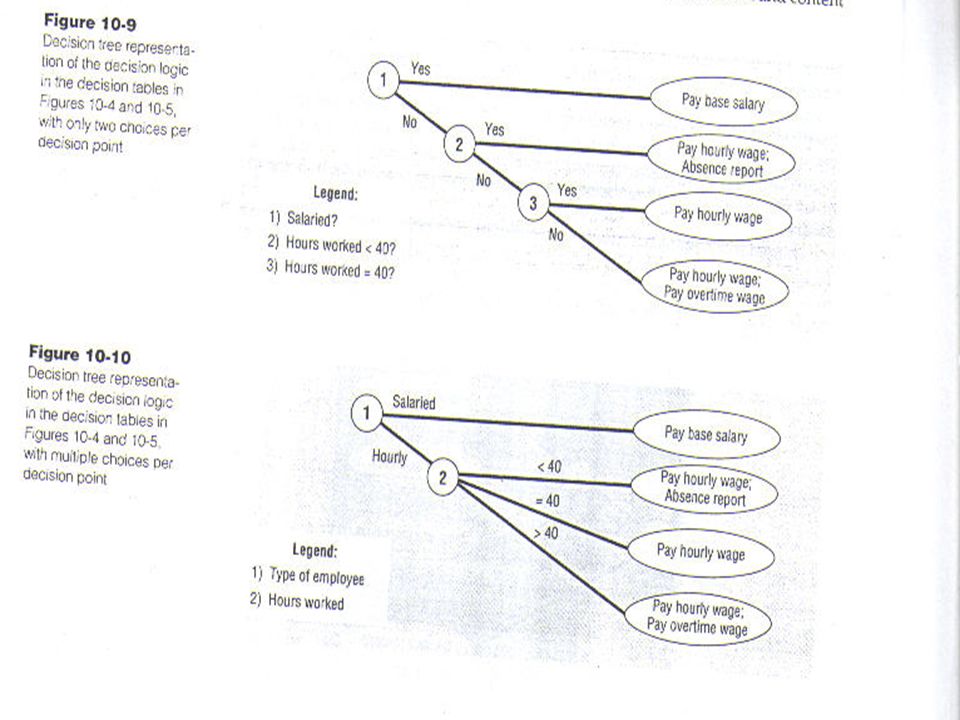
Use Structured English if many repetitive actions. Use Decision Tables if complex combinations of conditions, actions and rules. Use Decision Trees when the sequence of conditions and actions is important.

114
Structured English Constructs
sequence, selection, repetition/iteration Sequence: actions which take place one after the other. Find a teapot Put in the tea Pour in boiling water

115
Structured English Constructs
Selection: IF-THEN-ELSE construct IF condition A THEN action B ELSE action C ENDIF

116
Structured English Constructs
IF you like tea THEN drink tea ELSE drink coffee ENDIF

117
Structured English Constructs
Repetition: a block of statements that are repeated until some condition is met. DOWHILE there are customers greet the customer hand over the goods take the money run ENDDO

118
Structured English The following scenario is described by a clerk, who carries out the task of pricing the orders: I get the stack of orders to price. I go through the orders one by one until I have priced them all. I price each item on the order in turn by consulting the sales catalogue. Sometimes I cannot find the item because it is a new product and I then have to look at the supplement. If I have no luck there, I put a question mark on the form. Then I put the priced order in the out tray. When all the orders have been priced, I take the stack from the out tray and place it in the credit control section’s in tray. Write Structured English for the pricing process described above.

119
Structured English Get stack of orders
DOWHILE there are orders in the stack get the top order DOWHILE there are un priced items on the order get next un priced item IF item is in the catalogue THEN write item price on the order ELSE IF item price is in the supplement

120
THEN write item price on the order
ELSE write ? on the order ENDIF ENDDO put order in the out tray get the stack from the out tray put the stack in the credit control section’s in tray

124
Advantages Allows us to construct complex descriptions of business policy. Concise, precise and readable. Can be written quickly. Can be co-ordinated to the DD and DFD to check consistency.

125
Decision Trees Distinguish between conditions and actions.
Identify all conditions and actions and the ORDER. Identifies the decision paths at each node. Each node represents a question. Answers are TRUE or FALSE. Build tree from left to right.

130
Decision Tables A method of laying out conditions and actions in a table format. A concise way of representing the logic of a process. Shows actions to be taken under differing combinations of conditions.

131
Condition Alternatives
Decision Tables A decision table is a table composed of rows and columns, separated into four separate quadrants. Conditions Condition Alternatives Actions Action Entries The upper left quadrant contains the conditions. The upper right quadrant contains the condition rules ofr alternatives. The lower left quadrant contains the actions to be taken and the lower right quadrant contains the action rules.

132
Decision Tables Easily understandable.
Unmatched for clarity and precision. Use if: selection of applicable action is dependent on a number of conditions.

133
Problems With Use May be hard to know where to begin with a decision table formulation. Users unfamiliar with them. Call it “a table that describes a particular situation.”

134
Developing Decision Tables
Determine the conditions affecting the decision. (rows in top half of table) Determine number of possible actions. (rows in bottom half of table)
 Determine number of possible actions. (rows in bottom half of table)")
135
Developing Decision Tables
A rule describes the action to be carried out for a specific combination of values of the conditions. At least one action must be specified for each rule.

136
Developing Decision Tables
If we have an application with 3 conditions, we will need ? distinct rules 2x2x2 = 8 rules

137
Developing Decision Tables
Create “empty” decision table. List all conditions and actions on left hand side. Number combinations of conditions along top of the table. List all the combinations of conditions, one for each vertical column in the table. For each column, identify the action to be taken.

138
Developing Decision Tables
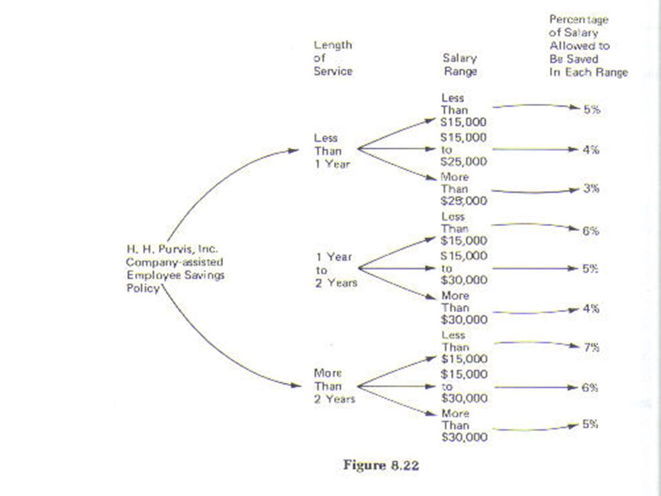
You are the Green-Keeper at a golf club. If the grass is too long, cut it. If there are weeds, apply weed-killer. Otherwise, sit in a chair and enjoy the sun. Grass too long Y Y N N Weeds Y N Y N Cut grass X X - - Apply weed killer X - X - Sit down X

139
Each condition has 2 values.
Therefore no. of rules is 4.

140
Rationalizing Decision Tables
Can reduce DTs by combining columns. Combine rules where the condition does not affect the action.

141
Decision Tables Must discuss each rule with the user.
Common the user has not thought about certain combinations of conditions. Advantage of decision tables is that you can concentrate on one rule at a time.

145
The possible actions that a cashier could take are agreed as:
An Example A store wishes to program a decision on non-cash receipts for goods into their intelligent tills. The conditions to check are agreed as: 1. Transaction under £50 2. Pays by cheque with cheque card (guarantee £50) 3. Pays by credit card The possible actions that a cashier could take are agreed as: 1. Ring up sale 2. Check credit card from local database 3. Call a supervisor 4. Automatic check of credit card company database
 3. Pays by credit card. The possible actions that a cashier could take are agreed as: 1. Ring up sale 2. Check credit card from local database 3. Call a supervisor 4. Automatic check of credit card company database.")
146
Check from local database
The condition rules are yes or no, therefore the number of possible condition rules are 2 alternatives for condition 1 x 2 alternatives for condition 2 x 2 alternatives for condition 3 or 2 3 = 8 Under £50 Y Y N Pays by cheque Pays by credit card Ring up sale Check from local database Call Supervisor Check credit card database

147
We can see that some of the condition rules are invalid, the customer cannot pay by cheque AND pay by credit card or not pay by either method. We have decided that these combinations are mutually exclusive. This decision table can be reduced to 4 condition rules. Under £50 Y N Pays by cheque Pays by credit card Ring up sale Check from local database Call Supervisor Check credit card database

148
Indicate the actions. Under £50 Y N Pays by cheque Pays by credit card Ring up sale X Check from local database Call Supervisor Check credit card database

149
What if the customer has not shopped their before
What if the customer has not shopped their before? Missing some as obvious as this means reconstructing the table!

150
The conditions are now:
1. Transaction under £50 2. Pays by cheque with cheque card (guarantee £50) 3. Pays by credit card 4. Unknown customer The actions remain the same but the number of condition rules increases by a multiple of 2.
 3. Pays by credit card 4. Unknown customer. The actions remain the same but the number of condition rules increases by a multiple of 2.")
151
Under £50 Y Y N Pays by cheque Pays by credit card N Unknown customer Ring up sale Check from local database Call Supervisor Check credit card database

154
The DATA DICTIONARY (for DFDs)
Concepts and Examples

155
Data Dictionary part of the specifications for a complete
Dataflow Analysis (DFD) ER model OOAD model SADT etc.
 ER model. OOAD model. SADT. etc.")
156
Data Dictionary for a DFD
specifies data elements in a DFD: data flows simple data stores must be consistent with DFD specification compatible with diagram must be complete with regard to the DFD consists of data item specifications

157
Data Item Specification
name (and aliases) informal description purpose range of values related data items connections to processes (flow information) formal data structure specification
 informal description. purpose. range of values. related data items. connections to processes (flow information) formal data structure specification.")
158
Patient Data Record name: patient data record (PDR) description:
A PDR is produced by the Patient Monitoring System and includes information on the current status of a specific patient in the intensive care unit, e.g. blood pressure, temperature, etc. A PDR is produced every five minutes.

159
Patient Data Record purpose: range of values:
Used to feed the Patient DB with up-to-date information on each patient. PDRs are accumulated, i.e. the average value of all received readings during a full hour is stored. range of values: see specifications of PDR sub-elements

160
Patient Data Record related data items: derived items: is-part-of:
PDR - Patient Input is-part-of: N/A (PDR has no super-ordinate element)
")
161
Patient Data Record related data items:
is-decomposed-into (sub-ordinate elem.): patient-id patient-name (first and last) heart-rate temperature blood-pressure (optional)
: patient-id. patient-name (first and last) heart-rate. temperature. blood-pressure (optional)")
162
Patient Data Record related data items:
is-decomposed-into (continued): status (critical or non-critical) delta values for heart-rate, temperature, blood-pressure as calculated during the last hour comparing to the full hour value (minimum 1, maximum 12)
: status (critical or non-critical) delta values for. heart-rate, temperature, blood-pressure. as calculated during the last hour. comparing to the full hour value. (minimum 1, maximum 12)")
163
Patient Data Record connections to processes: comes from: goes to:
Patient Monitoring System (external source) goes to: check & accum. PDR (system internal process)
 goes to: check & accum. PDR. (system internal process)")
164
Formal Data Structure Definition?
BNF - Backus-Naur-Form: formal language context free grammar based on substitution rules widely used to specify syntax of programming languages

165
BNF rules used to specify substitution/refinement/structuring:
data-item ==> data-structure person ==> name + address name ==> first_name + last_name

166
BNF + sequence [...|...|...] exclusive alternatives
meta-symbols used to describe structure: + sequence [...|...|...] exclusive alternatives { ... } iteration (>=1 repetitions) ( ... ) option
![BNF + sequence [...|...|...] exclusive alternatives](http://slideplayer.com/slide/6351203/22/images/166/BNF+%2B+sequence+%5B...%7C...%7C...%5D+exclusive+alternatives.jpg "meta-symbols used to describe structure: + sequence. [...|...|...] exclusive alternatives. { ... } iteration (>=1 repetitions) ( ... ) option.")
167
Patient Data Record - BNF
formal structure specification: PDR ==> p_id + p_name + c_val + status + {d_val} p_name ==> first_name + last_name c_val ==> heart_rate + temp + ( blood_pressure ) status ==> [ “critical” | “non-critical” ] d_val ==> d_heart + d_temp + ( d_blood )
 status ==> [ critical | non-critical ] d_val ==> d_heart + d_temp + ( d_blood )")
171
Design Quality in software systems

172
Coupling The strength of a connection between two routines
High quality routines exhibit loose coupling Indicates how strongly a routine is related to other routines Good coupling between routines is loose enough that one routine can easily be called by other routines

173
Coupling Criteria Visibility Flexibility
the prominence of the connection between two routines parameter passing, documented global data sharing, undocumented global data sharing Flexibility how easily the connection between routines can be changed

174
Cohesion A measure of how well a component 'fits together'
A component should implement a single logical entity or function Cohesion is a desirable design component attribute as when a change has to be made, it is localized in a single cohesive component Various levels of cohesion have been identified

176
Requirements Definition and Specification
Techniques for defining and specifying software system requirements

177
Objectives To illustrate a forms-based method of writing requirements definition To describe ways of writing precise specifications To explain the importance of non-functional requirements To describe different types of non-functional requirement and how these can be specified

178
Topics covered Requirements definition Requirements specification
Non-functional requirements

179
Definition and specification
Requirements definition Customer-oriented descriptions of the system’s functions and constraints on its operation Requirements specification Precise and detailed descriptions of the system’s functionality and constraints. Intended to communicate what is required to system developers and serve as the basis of a contract for the system development

180
Requirements definition
Should specify external behaviour of the system so the requirements should not be defined using a computational model Includes functional and non-functional requirements Functional requirements are statements of the services that the system should provide Non-functional requirements are constraints on the services and functions offered by the system

181
Writing requirements definitions
Natural language, supplemented by diagrams and tables is the normal way of writing requirements definitions This is universally understandable but three types of problem can arise Lack of clarity. Precision is difficult without making the document difficult to read Requirements confusion. Functional and non-functional requirements tend to be mixed-up Requirements amalgamation. Several different requirements may be expressed together

182
Functional requirements
1. The website system should provide a comprehensive well-structured content representing the multinational company. 2. The marketing department should be able to use the website system as a powerful tool to support is marketing goals world-wide and improve customer service. 3. All types of visitors should be able to have a rapid access to the site and its contents and services . 4. The system should be quite informative , interactive , and impressive . 5. Website security is a critical issue for both owners and customers . 6. The system should be able generate self-evaluation of its performance . 7. The website system must be easily controlled and navigated for both visitor and operator . Functional requirements

183
Non-functional requirements
The non-functional requirements of the project are as follows : 1- User considerations : The system must be simple enough for those that are relatively inexperienced to be able to access and use , yet still fulfill our project goals . 2- Reasonable response time : The system should respond to the user in reasonable response time when reply to order request or being communicated by . 3 - Complete Popular Browsers support : The system should support successful viewing on both Netscape navigator and Microsoft Explorer Browsers . 4 - Database compatibility : The system should be compatible with the Access 2000 database ending and Access 2000 file format . Non-functional requirements

184
5 - Authoring tool support :
Any authoring tool used to edit the HTML code or the web site design must be compatible with MS-Front page (2000) considerations . 6 - System platform : The platform will have to store the operating system (Windows 98) along with Frontpage 2000 and MS - Office 7 - Hardware Requirements : The system should run on the following minimum hardware requirements : - PENTIUM 75 MHZ PROCESSOR . - 16 MB RAM ( 32 RAM IS RECOMMENDED ) . - FREE HD SPACE NOT LESS THAT 100 MB . - A MODEM SPEED NOT LESS THAN 33.6 KBPS (56.6 KBPS RECOMMENDED ) .
 considerations System platform : The platform will have to store the operating system (Windows 98) along with Frontpage 2000 and MS - Office Hardware Requirements : The system should run on the following minimum hardware requirements : - PENTIUM 75 MHZ PROCESSOR MB RAM ( 32 RAM IS RECOMMENDED ) . - FREE HD SPACE NOT LESS THAT 100 MB . - A MODEM SPEED NOT LESS THAN 33.6 KBPS (56.6 KBPS RECOMMENDED ) .")
185
Requirements specifications
1.1 The system contents must include the mother company , intranet departments , and sister companies . 1.2 The system should focus on company present and future ambitions with a fair coverage of the company history . 1.3 The website should include all types of presentation media such as text , graphics , charts , images , multimedia clips , and links to give full coverage about company people and activities . 1.4 The site contents should be updated daily to cover new activities , new products and important news . 2.1 The M.D ( marketing department ) should be able to sell company products on-line . 2.2 The system should enable M.D to inform present customers of products updates. Requirements specifications
 should be able to sell company products. on-line The system should enable M.D to inform present customers of products updates. Requirements specifications.")
186
ERM

188
Implementing Effective Systems
If you do not understand organizational data and cannot represent the data requirements of an application unambiguously in logical terms, you cannot implement a system that will effectively serve the needs of management or users.

189
Data Modeling Shows the definition, structure, and relationships within data. Process modeling only shows how, where & when data is used.

190
Conceptual data model Conceptual Data Model
Is a detailed data model that captures the overall structure of organizational data, Is independent of DBMS. Shows as many rules about the meaning and interrelationships among data as possible Is what the organization does and rules that govern how the work is done primary deliverable Entity Relationship Diagram

192
Entity Relationship Diagram IS:
a logical representation of: entities, attributes, and relationships. Let’s examine each of these...

193
Entity Entity (object/noun)
person, place, object, event, or concept of interest

194
An Instance of this entity
Entities An entity is a person, place or object, event, or concept of interest An instance is a single occurrence of an entity Entity An Instance of this entity

195
A word about entities... An ERD entity is not the same as a source or sink in a Data Flow Diagram. There will usually be multiple instances. Data entities have to be described by attributes.

196
Attributes Let’s look as some attributes which identify entity instances. They may or may not be unique. They may be “composite” attributes. Unique Attribute Composite Non-unique Attribute Non-unique Attribute

197
Hoffer’s take on Keys Entities must have an identifier. Candidate Key
an attribute(s) that uniquely identifies each instance of an entity. (e.g. SSN and Name) Out of the multiple candidate, only one is selected to be “the” Identifier the candidate key selected as the identifier for an entity. (e.g. SSN)
 that uniquely identifies each instance of an entity. (e.g. SSN and Name) Out of the multiple candidate, only one is selected to be the Identifier. the candidate key selected as the identifier for an entity. (e.g. SSN)")
198
For purposes of our discussion...
Entities must have a primary key. Primary Key a key that uniquely identifies each instance of an entity (ex: SSN) Secondary Key a key that cannot uniquely identify each instance of an entity but can be used to select a group of records that belong to a set (ex: Aggies that come from Texas) Starting to sound a little bit like Info428?
 Secondary Key. a key that cannot uniquely identify each instance of an entity but can be used to select a group of records that belong to a set (ex: Aggies that come from Texas) Starting to sound a little bit like Info428")
199
More on the subject of keys
Concatenated Key: When it is not possible to identify each instance of a relationship uniquely by choosing one of the attributes in the entity, a key can be constructed by choosing two or more attributes and combining them. For example: 99C-Info320-Section 504 Hoffer’s Candidate Keys include concatenated or other single attributes.

200
Attributes Characteristic of an entity
May have a “composite” attributes Also known as “field” Multivalued attribute has more than 1 value for a given instance of an entity. (e.g. phone although not shown) Attributes Composite Attribute Attribute Values
 Attributes. Composite Attribute. Attribute Values.")
201
Relationship An association between two or more entities
a verb phrase connecting entities Directional Event Something happens Linkage We will use the Crow’s Foot notation style

202
One-to-one An EMPLOYEE is assigned one PARKING SPACE.
A PARKING SPACE is assigned to one EMPLOYEE. PARKING SPACE EMPLOYEE One-to-many An EMPLOYEE supports many DEPENDENTs. A DEPENDENT is supported by one EMPLOYEE. EMPLOYEE DEPENDENT Many-to-many An EMPLOYEE is assigned to many PROJECTs A PROJECT is assigned many EMPLOYEEs. EMPLOYEE PROJECT

203
Degree of Relationship
unary - one entity is related to itself (recursive) binary - two entities are related EMPLOYEE EMPLOYEE DEPENDENT
 binary - two entities are related. EMPLOYEE. EMPLOYEE. DEPENDENT.")
204
Degree of Relationship (2)
ternary - three entities are related PROJECT EMPLOYEE SOFTWARE TOOL

206
Cardinality the number of instances of entity-B that can be associated with each instance of entity-A. specify both minimum and maximum cardinalities for each relationship Minimum 0 (i.e.. optional) 1 (i.e.. mandatory) Maximum 1 many
 1 (i.e.. mandatory) Maximum. 1. many.")
207
In other words... The lower and upper bounds on number of occurrences involved on each side of a relationship zero one many specific number 1:1 1:M M:N

208
One-to-one PARKING SPACE EMPLOYEE One-to-many EMPLOYEE DEPENDENT Many-to-many EMPLOYEE PROJECT

209
Entity Relationship Diagram (ERD)
PARKING SPACE EMPLOYEE PROJECT DEPENDENT SOFTWARE TOOL

210
Steps for Creating an ERD
Identify the entities Identify the attributes Identify the relationships Identify cardinalities maximum minimum Set business rules - discuss next time

211
A Simple Example to Dream On
Each semester each student must be assigned an advisor who counsels students about degree requirements and helps students register for classes.

212
A Simple Example to Dream On
Each semester each student must be assigned an advisor who counsels students about degree requirements and helps students register for classes. counsel Students Advisors

213
More about Attributes Primary Key Attribute Multivalued Attribute

214
Some Examples Employee No. Employee Dep-Relation Dep-Name Employee No.
Dep-Name, Dep-age, Dep-relation Employee No. Employee Dep-Relation Dep-Name Employee No. Dep-Age Employee Dependent

215
Types of Entities Fundamental Entity Associative Entity (Gerund)
regular rectangle (exist by themselves) Associative Entity (Gerund) result from many to many relationship Attributive Entity (Weak Entity) only exists because of the existence of some other entity
 Associative Entity (Gerund) result from many to many relationship. Attributive Entity (Weak Entity) only exists because of the existence of some other entity.")
216
Associative Entity (Gerund)
shipment Warehouse Vendor Shipment No. Quantity Part

217
Attributive Entity (Weak Entity)
Dep-Relation Dep-Name Employee No. Dep-Age Employee Dependent

218
ERD Practice A company has employees (Name, Address, birth date) and projects (code, description, start date). Each employee may be assigned to one or more projects, or may not be assigned to a project. A project must have at least one employee assigned, and may have several employees assigned.
 and projects (code, description, start date). Each employee may be assigned to one or more projects, or may not be assigned to a project. A project must have at least one employee assigned, and may have several employees assigned.")
219
ERD Practice (2) A laboratory has several chemists (ID, Name, phone number) who work on projects (project ID, start date); certain kinds of equipment (number, cost) may be used by chemists on projects.
 who work on projects (project ID, start date); certain kinds of equipment (number, cost) may be used by chemists on projects.")
220
ERD Practice (3) A company has employees (name, title) work work in departments (d-num, manager name); All employees work in at most one department, and all departments have at least one employee. Each employee has zero, one, or more dependents (dep-name, age) Also, each department is managed by one employee, who can manage at most one department.
 work work in departments (d-num, manager name); All employees work in at most one department, and all departments have at least one employee. Each employee has zero, one, or more dependents (dep-name, age) Also, each department is managed by one employee, who can manage at most one department.")
221
ERD Data Sources Data entry forms (paper and screen)
Reports (paper and screen) Existing Databases DFDs (if completed. Each data flow must be an attribute of some entity. Data stores may be associated with entities.) Interviews, questionnaires, JAD
 Existing Databases. DFDs (if completed. Each data flow must be an attribute of some entity. Data stores may be associated with entities.) Interviews, questionnaires, JAD.")
222
What to ask during Requirements Determination

223
Steps for Creating an ERD
Identify the entities Identify the attributes Identify the relationships Identify cardinalities maximum minimum Set business rules

224
Four Types of Business Rules
1. Entity integrity - each instance of an entity type must have a unique identifier that is not null. 2. Referential integrity constraints - rules concerning the relationships between entity types (chapter 16) 3. Domains - constraints on valid values for attributes 4. Triggering operations - other business rules that protect the validity of attribute values
 3. Domains - constraints on valid values for attributes. 4. Triggering operations - other business rules that protect the validity of attribute values.")
225
Business Rules Done after most of the diagram is complete Examples:
A technician must have an electrician certificate if performing an inspection service A technician may only have a vehicle if (s)he has been employed more than 30 days
he has been employed more than 30 days.")
226
How do you build an ERD for your case project?
Here is a cookbook approach to creating an ERD

227
Cookbook 1 Derive a high level, first cut data model
What are the techniques? look at forms, look at existing database, Identify data entities What are the entities of interest around which data must be stored? “Model the world” be more rather than less comprehensive

228
Cookbook 2 Identify likely attributes of those entities
What are the keys? (Primary, Alternate, Foreign) How should you name them? Determine what type each is Determine constraints (cardinalities) of attributes Determine relationships among entities How are they related? Optional or mandatory? Fundamental, attributive, and associative entities What are the cardinalities of the relationships?
 How should you name them Determine what type each is. Determine constraints (cardinalities) of attributes. Determine relationships among entities. How are they related Optional or mandatory Fundamental, attributive, and associative entities. What are the cardinalities of the relationships")
Similar presentations


 Modeling>")


 Concepts and Examples.>")


