Download presentation
Presentation is loading. Please wait.

1
SE 292: High Performance Computing Memory Organization and Process Management Sathish Vadhiyar

2
Memory Image of a Process – Structure of a process in main memory A process consists of different sections (shown in the figure) in main memory A process also includes current activity Program counter Process registers Text Code Uninitialized Initialized Data Heap Stack Memory mapped region for shared libraries Text Data Text a.out libc.so
 in main memory A process also includes current activity Program counter Process registers Text Code Uninitialized Initialized Data Heap Stack Memory mapped region for shared libraries Text Data Text a.out libc.so")
3
Memory Image Data section contains global variables (initialized & unitialized) The memory image also consists of shared libraries used by a program (more later)
 The memory image also consists of shared libraries used by a program (more later)")
4
Memory Image Stack Stack contains temporary data Holds function parameters, return addresses, local variables Expands and contracts by function calls and returns, respectively Addresses calculated and used by compiler, relative to the top of stack, or some other base register associated with the stack Growth of stack area is thus managed by the program, as generated by the compiler

5
Memory Image Heap Heap is dynamically allocated Expands and contracts by malloc & free respectively Managed by a memory allocation library

6
Memory Abstraction Above scheme requires entire process to be in memory What if process space is larger than physical memory? Virtual memory Provides an abstraction to physical memory Allows execution of processes not completely in memory Offers many other features

7
Virtual Memory Concepts Instructions must be in physical memory to be executed But not all of the program need to be in physical memory Each program could take less memory; more programs can reside simultaneously in physical memory Need for memory protection One program should not be able to access the variables of the other Typically done through address translation (more later)
")
8
page 0 page 1 page 2 page v Virtual Memory Memory Map Physical Memory page 2 Virtual memory can be extremely large when compared to a smaller physical memory Virtual Memory Concepts – Large size

9
code data heap stack code data heap stack Memory Map shared library Virtual Memory Concepts - Sharing Virtual memory allows programs to share pages and libraries

10
Address Translation Terminology – Virtual and Physical Addresses Virtual memory addresses translated to physical memory addresses Memory Management Unit (MMU) provides the mapping MMU – a dedicated hardware in the CPU chips Uses a lookup table (see below) To translate a virtual address to the corresponding physical address, a table of translation information is needed
 provides the mapping MMU – a dedicated hardware in the CPU chips Uses a lookup table (see below) To translate a virtual address to the corresponding physical address, a table of translation information is needed")
11
Address Translation Minimize size of table by not managing translations on byte basis but larger granularity Page: fixed size unit of memory (contiguous memory locations) for which a single piece of translation information is maintained The resulting table is called page table The contents of the page table managed by OS Thus, (address translation logic in MMU + OS + page table) used for address translation
 for which a single piece of translation information is maintained The resulting table is called page table The contents of the page table managed by OS Thus, (address translation logic in MMU + OS + page table) used for address translation")
12
Address Translation 0x00000000 0x00000100 0xFFFFFFFF 0x00000200 0x000000FF 256 Bytes Virtual Address Space Virtual Page 0 Virtual Page 1 Virtual Page 0xFFFFFF … … Physical Address Space 0x000000 0xFFFFFF 0x0000FF 256 Bytes Physical Page 0 … 0x000001FF PROGRAM/PROCESS MAIN MEMORY Text Data Stack Heap 0x00000000 0x00000100 0x00000200 0xFFFFFFFF 0x000000FF 0x000001FF 0x00000124: 0x000024:

13
Address Translation Virtual address Translation table Physical address Virtual page number (VPN) Offset VPN PPN Physical Page Number (PPN) Offset PAGE TABLE
 Offset VPN PPN Physical Page Number (PPN) Offset PAGE TABLE")
14
Size of Page Table Big Problem: Page Table size Example: 32b virtual address, 16KB page size 256K virtual pages => MB page table size per process Has to be stored in memory Solution – Multi-level page table (more later)
")
15
Address Translation Page Table Base Register (PTBR) Virtual Page Number (VPN)Virtual Page Offset (VPO) Physical Page Number (PPN) Virtual Address (n-bit) Physical Address (m-bit) Physical Page Offset (PPO) 0p-1pn-1 0p-1pm-1 ValidPhysical Page Number (PPN) Page Table Fig 10.13 (Bryant)
 Virtual Page Number (VPN)Virtual Page Offset (VPO) Physical Page Number (PPN) Virtual Address (n-bit) Physical Address (m-bit) Physical Page Offset (PPO) 0p-1pn-1 0p-1pm-1 ValidPhysical Page Number (PPN) Page Table Fig (Bryant)")
16
What’s happening… Disk P1P2Pn … Virtual page contents Main Memory 1 1 2 2 3 3 4 4 Page Tables P1 P2 Pn 1 1 1 1 2 2 2 2 3 3 3 4 4 4 4 3 - - - - - - - - … Processes

17
Demand Paging When a program refers a page, the page table is looked up to obtain the corresponding physical frame (page) If the physical frame is not present, page fault occurs The page is then brought from the disk Thus pages are swapped in from the disk to the physical memory only when needed – demand paging To support this, the page table has valid and invalid bits Valid – present in memory Invalid – present in disk
 If the physical frame is not present, page fault occurs The page is then brought from the disk Thus pages are swapped in from the disk to the physical memory only when needed – demand paging To support this, the page table has valid and invalid bits Valid – present in memory Invalid – present in disk")
18
Page Fault Situation where virtual address generated by processor is not available in main memory Detected on attempt to translate address Page Table entry is invalid Must be `handled’ by operating system Identify slot in main memory to be used Get page contents from secondary memory Part of disk can be used for this purpose Update page table entry Data can now be provided to the processor

19
Demand Paging (Valid-Invalid Bit) Fig. 9.5 (Silberschatz)
 Fig. 9.5 (Silberschatz)")
20
Page Fault Handling Steps Fig. 9.6 (Silberschatz)
")
21
Page Fault Handling – a different perspective Processor MMU Cache/ Memory Disk Page fault exception handler CPU chip VA PTEA PTE Exception Victim page New page 1 2 3 4 5 6 7 Fig. 10.14 (Bryant)
.")
22
Page Fault Handling Steps 1. Check page table to see if reference is valid or invalid 2. If invalid, a trap into the operating system 3. Find free frame, locate the page on the disk 4. Swap in the page from the disk 1. Replace an existing page (page replacement) 5. Modify page table 6. Restart instruction
 5. Modify page table 6. Restart instruction.")
23
Performance Impact due to Page Faults p – probability of page fault ma – memory access time effective access time (EAT) – (1-p) x ma + p x page fault time Typically EAT = (1-p) x (200 nanoseconds) + p(8 milliseconds) = 200 + 7,999,800 x p nanoseconds Dominated by page fault time
 – (1-p) x ma + p x page fault time Typically EAT = (1-p) x (200 nanoseconds) + p(8 milliseconds) = ,999,800 x p nanoseconds Dominated by page fault time")
24
So, What happens during page fault? 1. Trap to OS, Save registers and process state, Determine location of page on disk 2. Issue read from the disk 1. major time consuming step – 3 milliseconds latency, 5 milliseconds seek 3. Receive interrupt from the disk subsystem, Save registers of other program 4. Restore registers and process state of this program To keep EAT increase due to page faults very small (< 10%), only 1 in few hundred thousand memory access should page fault i.e., most of the memory references should be to pages in memory But how do we manage this? Luckily, locality And, smart page replacement policies that can make use of locality
, only 1 in few hundred thousand memory access should page fault i.e., most of the memory references should be to pages in memory But how do we manage this. Luckily, locality And, smart page replacement policies that can make use of locality.")
25
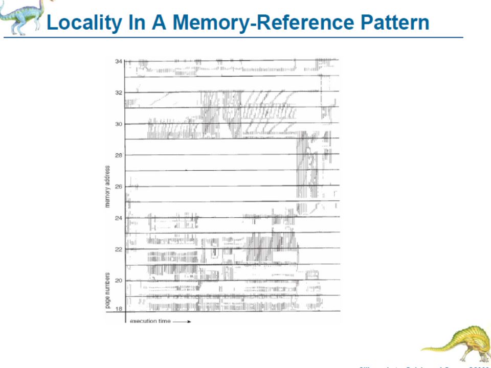
Page Replacement Policies Question: How does the page fault handler decide which main memory page to replace when there is a page fault? Principle of Locality of Reference A commonly seen program property If memory address A is referenced at time t, then it and its neigbhouring memory locations are likely to be referenced in the near future Suggests that a Least Recently Used (LRU) replacement policy would be advantageous temporal spatial
 replacement policy would be advantageous temporal spatial.")
26
Locality of Reference Based on your experience, why do you expect that programs will display locality of reference? Program Data Same address (temporal) Neighbours (spatial) Loop Function Sequential code Loop Local Loop index Stepping through array
 Neighbours (spatial) Loop Function Sequential code Loop Local Loop index Stepping through array.")
27
Page Replacement Policies FIFO – performance depends on if the initial pages are actively used Optimal page replacement – replace the page that will not be used for the longest time Difficult to implement Some ideas? LRU Least Recently Used is most commonly used Implemented using counters LRU might be too expensive to implement

28
Page Replacement Algorithms - Alternatives LRU Approximation – Second-Chance or Clock algorithm Similar to FIFO, but when a page’s reference bit is 1, the page is given a second chance Implemented using a circular queue Counting-Based Page Replacement LFU, MFU Performance of page replacement depends on applications Section 9.4.8

29
Managing size of page table – TLB, multi- level tables Translation Lookaside Buffer – a small and fast memory for storing page table entries MMU need not fetch PTE from memory every time TLB is a virtually addressed cache TLB tag (TLBT)TLB index (TLBI)VPO 0p-1pp+t-1p+tn-1 Processor Translation TLB Cache/ Memory VA VPNPTE PA Data 1 23 4
TLB index (TLBI)VPO 0p-1pp+t-1p+tn-1 Processor Translation TLB Cache/ Memory VA VPNPTE PA Data")
30
Speeding up address translation Translation Lookaside Buffer (TLB): memory in MMU that contains some page table entries that are likely to be needed soon TLB Miss: required entry not available
: memory in MMU that contains some page table entries that are likely to be needed soon TLB Miss: required entry not available")
31
Multi Level Page Tables A page table can occupy significant amount of memory Multi level page tables to reduce page table size If a PTE in level 1 PT is null, the corresponding level 2 PT does not exist Only level-1 PT needs to be in memory. Other PTs can be swapped in on- demand. PTE 0 PTE 1 PTE 2 PTE 3 PTE 4 PTE 5 PTE 6 … … null Level 1 page table Level 2 page tables

32
Multi Level Page Tables (In general..) Each VPN i is an index into a PT at level i Each PTE in a level j PT points to the base of some PT at level (j+1) VPN 1VPN 2…VPN kVPO PPNPPO 0p-1n-1 PPN 0 p-1m-1 Virtual Address Physical Address fig. 10.19 (Bryant)
.")
33
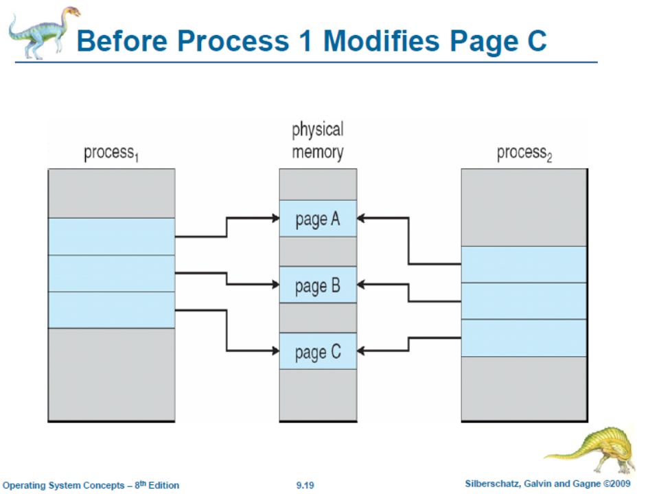
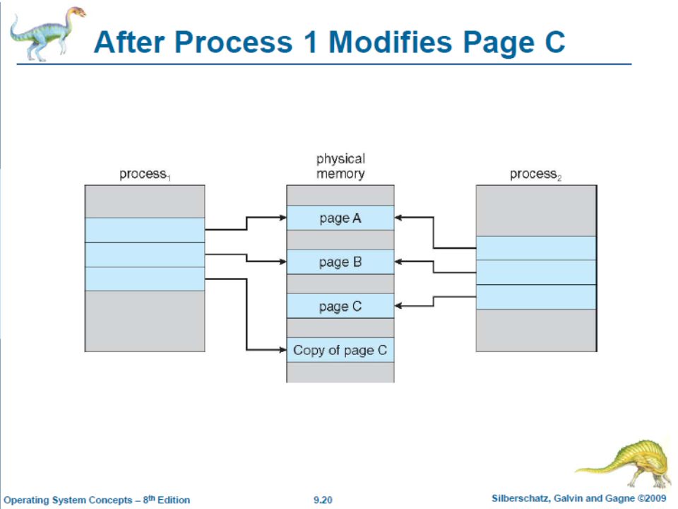
Virtual Memory and Fork During fork, a parent process creates a child process Initially the pages of the parent process is shared with the child process But the pages are marked as copy-on- write. When a parent or child process writes to a page, a copy of a page is created.

36
Dynamic Memory Allocation Allocator – Manages the heap region of the VM Maintains a list of “free” in memory and allocates these blocks when a process requests it Can be explicit (malloc & free) or implicit (garbage collection) Allocator’s twin goals Maximizing throughput and maximizing utilization Contradictory goals – why?
 or implicit (garbage collection) Allocator’s twin goals Maximizing throughput and maximizing utilization Contradictory goals – why")
37
Components of Memory Allocation The heap is organized as a free list When an allocation request is made, the list is searched for a free block Search method or placement policy First fit, best fit, worst fit Coalescing – merging adjacent free blocks Can be immediate or deferred Garbage collection – to automatically free allocated blocks no longer needed by the program

38
Fragmentation Cause of poor heap utilization An unused memory is not available to satisfy allocate requests Two types Internal – when an allocated block is larger than the required payload External – when there is enough memory to satisfy a free request, but no single free block is large enough

39
Process Management

40
Computer Organization: Software Hardware resources of computer system are shared by programs in execution Operating System: special program that manages this sharing Ease-of-use, resource allocator, device controllers Process: a program in execution ps tells you the current status of processes Shell: a command interpreter through which you interact with the computer system csh, bash,…

41
Operating System, Processes, Hardware Hardware OS Kernel Processes System Calls

42
Operating System Software that manages the resources of a computer system CPU time Main memory I/O devices OS functionalities Process management Memory management Storage management

43
Process Lifetime Two modes User – when executing on behalf of user application Kernel mode – when user application requests some OS service, some privileged instructions Implemented using mode bits Silberschatz – figure 1.10

44
Modes Can find out the total CPU time used by a process, as well as CPU time in user mode, CPU time in system mode

45
Shell - What does a Shell do? while (true){ Prompt the user to type in a command Read in the command Understand what the command is asking for Get the command executed } Shell – command interpreter Shell interacts with the user and invokes system call Its functionality is to obtain and execute next user command Most of the commands deal with file operations – copy, list, execute, delete etc. It loads the commands in the memory and executes write read fork, exec Q: What system calls are involved?
{ Prompt the user to type in a command Read in the command Understand what the command is asking for Get the command executed } Shell – command interpreter Shell interacts with the user and invokes system call Its functionality is to obtain and execute next user command Most of the commands deal with file operations – copy, list, execute, delete etc. It loads the commands in the memory and executes write read fork, exec Q: What system calls are involved .")
46
System Calls How a process gets the operating system to do something for it; an interface or API for interaction with the operating system Examples File manipulation: open, close, read, write,… Process management: fork, exec, exit,… Memory management: sbrk,… device manipulation – ioctl, read, write information maintenance – date, getpid communications – pipe, shmget, mmap protection – chmod, chown When a process is executing in a system call, it is actually executing Operating System code System calls allow transition between modes

47
Mechanics of System Calls Process must be allowed to do sensitive operations while it is executing system call Requires hardware support Processor hardware is designed to operate in at least 2 modes of execution Ordinary, user mode Privileged, system mode System call entered using a special machine instruction (e.g. MIPS 1 syscall) that switches processor mode to system before control transfer System calls are used all the time Accepting user’s input from keyboard, printing to console, opening files, reading from and writing to files
 that switches processor mode to system before control transfer System calls are used all the time Accepting user’s input from keyboard, printing to console, opening files, reading from and writing to files.")
48
System Call Implementation Implemented as a trap to a specific location in the interrupt vector (interrupting instructions contains specific requested service, additional information contained in registers) Trap executed by syscall instruction Control passes to a specific service routine System calls are usually not called directly - There is a mapping between a API function and a system call System call interface intercepts calls in API, looks up a table of system call numbers, and invokes the system calls
 Trap executed by syscall instruction Control passes to a specific service routine System calls are usually not called directly - There is a mapping between a API function and a system call System call interface intercepts calls in API, looks up a table of system call numbers, and invokes the system calls")
49
Figure 2.9 (Silberschatz)
")
50
Traditional UNIX System Structure

51
System Boot Bootstrap loader – a program that locates the kernel, loads it into memory, and starts execution When CPU is booted, instruction register is loaded with the bootstrap program from a pre-defined memory location Bootstrap in ROM (firmware) Bootstrap – initializes various things (mouse, device), starts OS from boot block in disk Practical: BIOS – boot firmware located in ROM Loads bootstrap program from Master Boot record (MBR) in the hard disk MBR contains GRUB; GRUB loads OS OS then runs init and waits
 Bootstrap – initializes various things (mouse, device), starts OS from boot block in disk Practical: BIOS – boot firmware located in ROM Loads bootstrap program from Master Boot record (MBR) in the hard disk MBR contains GRUB; GRUB loads OS OS then runs init and waits")
52
Process Management What is a Process? Program in execution But some programs run as multiple processes And same program can be running multiply at same time

53
Process vs Program Program: static, passive, dead Process: dynamic, active, living Process changes state with time Possible states a process could be in? Running (Executing on CPU) Ready (to execute on CPU) Waiting (for something to happen)
 Ready (to execute on CPU) Waiting (for something to happen).")
54
Process State Transition Diagram RunningReady Waiting preempted or yields CPU scheduled waiting for an event to happen awaited event happens

55
Process States Ready – waiting to be assigned to a processor Waiting – waiting for an event Figure 3.2 (Silberschatz)
")
56
CPU and I/O Bursts Processes alternate between two states of CPU burst and I/O burst. There are a large number of short CPU bursts and small number of long I/O bursts

57
Process Control Block Process represented by Process Control Block (PCB). Contains: Process state text, data, stack, heap Hardware – PC value, CPU registers Other information maintained by OS: Identification – process id, parent id, user id CPU scheduling information – priority Memory-management information – page tables etc. Accounting information – CPU times spent I/O status information Process can be viewed as a data structure with operations like fork, exit etc. and the above data

58
PCB and Context Switch Fig. 3.4 (Silberschatz)
")
59
Process Management What should OS do when a process does something that will involve a long time? e.g., file read/write operation, page fault, … Objective: Maximize utilization of CPU Change status of process to `Waiting’ and make another process `Running’ Which process? Objective? Minimize average program execution time Fairness

60
Process Scheduling Selecting a process from many available ready processes for execution A process residing in memory and waiting for execution is placed in a ready queue Can be implemented as a linked list Other devices (e.g. disk) can have their own queues Queue diagram Fig. 3.7 (Silberschatz)
 can have their own queues Queue diagram Fig. 3.7 (Silberschatz).")
61
Scheduling Criteria CPU utilization Throughput Turnaround time Waiting time Response time Fairness

62
Scheduling Policies Preemptive vs Non-preemptive Preemptive policy: one where OS `preempts’ the running process from the CPU even though it is not waiting for something Idea: give a process some maximum amount of CPU time before preempting it, for the benefit of the other processes CPU time slice: amount of CPU time allotted In a non-preemptive process scheduling policy, process would yield CPU either due to waiting for something or voluntarily

63
Process Scheduling Policies Non-preemptive First Come First Served (FCFS) Shortest Process Next Preemptive Round robin Preemptive Shortest Process Next (shortest remaining time first) Priority based Process that has not run for more time could get higher priority May even have larger time slices for some processes
 Shortest Process Next Preemptive Round robin Preemptive Shortest Process Next (shortest remaining time first) Priority based Process that has not run for more time could get higher priority May even have larger time slices for some processes")
64
Example: Multilevel Feedback Used in some kinds of UNIX Multilevel: Priority based (preemptive) OS maintains one readyQ per priority level Schedules from front of highest priority non- empty queue Feedback: Priorities are not fixed Process moved to lower/higher priority queue for fairness
 OS maintains one readyQ per priority level Schedules from front of highest priority non- empty queue Feedback: Priorities are not fixed Process moved to lower/higher priority queue for fairness")
65
Context Switch When OS changes process that is currently running on CPU Takes some time, as it involves replacing hardware state of previously running process with that of newly scheduled process Saving HW state of previously running process Restoring HW state of scheduled process Amount of time would help in deciding what a reasonable CPU timeslice value would be

66
Time: Process virtual and Elapsed Elapsed time P1P2 P3 P1 P3 Process P1 virtual time P1 Process P1 virtual time : Running in user mode : Running in system mode Wallclock time Real time

67
How is a Running Process Preempted? OS preemption code must run on CPU How does OS get control of CPU from running process to run its preemption code? Hardware timer interrupt Hardware generated periodic event When it occurs, hardware automatically transfers control to OS code (timer interrupt handler) Interrupt is an example of a more general phenomenon called an exception
 Interrupt is an example of a more general phenomenon called an exception.")
68
Exceptions Certain exceptional events during program execution that are handled by processor HW Two kinds of exceptions Traps Page fault, Divide by zero, System call Interrupts Timer, keyboard, disk : Synchronous, software generated : Asynchronous, hardware generated

69
What Happens on an Exception 1.Hardware Saves processor state Transfers control to corresponding piece of OS code, called the exception handler 2.Software (exception handler) Takes care of the situation as appropriate Ends with return from exception instruction 3.Hardware (execution of RFE instruction) Restores the saved processor state Transfers control back to saved PC value
 Takes care of the situation as appropriate Ends with return from exception instruction 3.Hardware (execution of RFE instruction) Restores the saved processor state Transfers control back to saved PC value")
70
Re-look at Process Lifetime Which process has the exception handling time accounted against it? Process running at time of exception All interrupt handling time while process is in running state is accounted against it Part of `running in system mode’

71
More…

76
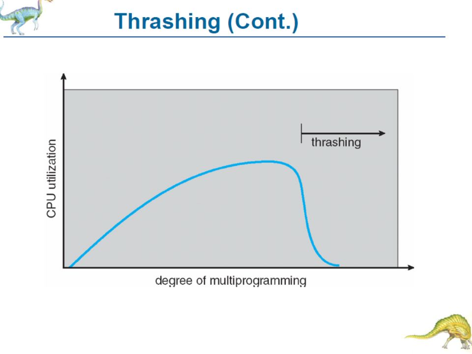
Trashing When CPU utilization decreases, OS increases multiprogramming level by adding more processes Beyond a certain multiprogramming level, processes compete for pages leading to page faults Page fault causes disk reads by processes leading to lesser CPU utilization OS adds more processes, causing more page faults, lesser CPU utilization – cumulative effect

Similar presentations


 LAS - Logical Address.>")


>")


>")


