Download presentation
Presentation is loading. Please wait.

1
Progress of BEPCII Cryogenic System Project Group of BEPCII Cryogenic System Institute of High Energy Physics, CAS IMAC meeting, Apr. 2006 Li Shaopeng

2
Contents Introduction Process of cryogenic system The commissioning of Two 500W/4.5K refrigerators The manufacture of various control valve boxes The manufacture of various cryogenic transfer-line The construction of cryogenic control The commissioning of SC cavity side cryogenic system with dummy load The further work of cryogenic system

3
Introduction (1) BEPCII cryogenic system mainly includes BESIII superconducting detector solenoid magnet (SSM), superconducting interaction quadrupole magnets(SCQ),superconducting RF cavities (SRF) cryogenic systems. The total refrigeration capacity of the cryogenic system is 1KW/4.5K, and the power supply requirement is 800KW. BEPCII cryogenic system will adopt two independent refrigerator systems each with a refrigeration capacity of 500W/4.5K to cool the SC magnets and SC RF cavities. A new cryogenic hall will be built at the northwest of the storage ring. The occupied area and construction area is about 800m2 and 400 m2 respectively.

4
Introduction (2) Helium compressor,air compressor, water cooling system, remote control system and various gas pipes are located in the cryogenic hall, and various GHe storage tank, and instrument-air tank are located out of the cryogenic hall.Superconducting equipments are installed in the tunnel of storage ring.The BESIII detector solenoid magnet and a pair quadrupole magnets of interaction region are positioned in the first colliding hall which is located at the south of the storage ring. The two SRF cavities are positioned in the second colliding hall which is located at the north of the storage ring. Two refrigerator coldbox are positioned nearby the first and the second colliding hall respectively.

5
Introduction (3) Valve boxes, control dewar are installed nearby the superconducting equipments, these equipments are connected by multi-channel or single channel transfer line. The connection between the cryogenic hall, refrigerator coldbox and superconducting equipments are made of high pressure helium supply pipe, low pressure return pipe and LN2 transfer line. The pipe distance between cryogenic hall and the first colliding hall, second colliding hall is about 200m and 100m respectively. The brief operation mode include pre-cooling mode, refrigeration mode, liquefy mode, operation mode, warm up mode and various safety protection mode. The control of the different operation mode and the monitoring of the status signals are accomplished by PLC and industry PC.

6
Layout of BEPCII cryogenic system

7
Process of cryogenic system(1) The BEPCII cryogenic system had completed a lot of work during the past time. Most of the standard products we purchased before have arrived and the nonstandard equipments we ordered in local market have arrived in succession. The cryogenic transfer lines manufactured by ourselves have approximately accomplished. The installation and commissioning of each apparatus and equipments had smoothly carried out. The construction of the BEPCII cryogenic system has been brought out a considerable process.

8
Process of cryogenic system(2) The main process are as following: Accomplished the civil works of the newly constructed cryogenic hall, the second colliding hall refrigerator room and the rebuilding first colliding hall refrigerator room Accomplished the electrical configuration of each hall Accomplished the manufacture and installation on site of the 7 gas tanks Accomplished the purge of the 4 set of 130m3 pure helium storage tanks Accomplished the installation 2 set of liquid nitrogen storage tanks Accomplished the installation of the 2 main compressors,recovery compressor, impure helium compressor, oil remove system, dryer in the cryogenic hall
 The main process are as following: Accomplished the civil works of the newly constructed cryogenic hall, the second colliding hall refrigerator room and the rebuilding first colliding hall refrigerator room Accomplished the electrical configuration of each hall Accomplished the manufacture and installation on site of the 7 gas tanks Accomplished the purge of the 4 set of 130m3 pure helium storage tanks Accomplished the installation 2 set of liquid nitrogen storage tanks Accomplished the installation of the 2 main compressors,recovery compressor, impure helium compressor, oil remove system, dryer in the cryogenic hall")
9
Process of cryogenic system(3) Accomplished the installation of the 2 set of refrigerators in the first and second colliding hall refrigerator room Accomplished the installation of the all warm pipes and tubes among the storage tank area, the refrigerator rooms and the cryogenic hall. At the same time accomplished the pressure test and the purge of them. Accomplished the installation and commissioning of the instruments air system and the cooling water system Accomplished the commissioning and the acceptation test of the 2 set of 500W/4.5K refrigerators Accomplished the manufacture, factory test, site installation and cooldown test of liquid helium temperature for the SRF distribute valve box and 1000L dewar control valve box.

10
Process of cryogenic system(4) Accomplished the manufacture, factory test of the 2 set of the SCQ valve boxes. The site installation and the connection with SCQ magnets are being performed and the cooldown test under the liquid helium temperature will be done soon. Accomplished the manufacture, factory test, site installation of various LHe and LN2 cryogenic transfer- line for connection between each cryogenic and superconducting equipment. The cooldown test under liquid helium temperature has been carried out.. The cryogenic control system of SC cavities and SC magnets has been established and the commissioning will attend by the process of cryogenic facilities.

11
Process of cryogenic system(5) The refrigerator operation training has been finished by ourselves, at the same time we tested the 1000L dewar and its valve box. Up to now there are 4 person can operate the refrigerator. Accomplished the commissioning of cryogenic system on SC cavities side with the dummy load at the SC test station. It is expected the further work for cryogenic system.

12
The commissioning of Two 500W/4.5K refrigerators (1) During the first test refrigeration capacity of Plant B without LN2 precooling. The ice forming appear on the header of 2000L test dewar when the heater power in the dewar reached to 40W, and then the refrigerator showed the operation status of fully cooling capacity of 270W when the heater power increased up to 110W. During the second test of Plant B with LN2 precooling after the modified the design of test dewar header. The ice forming appear when the heater power was at 140W and the refrigerator showed the fully capacity of 500W when the heater power was up to 270W

13
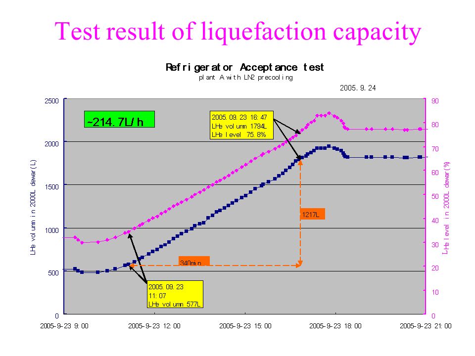
The commissioning of Two 500W/4.5K refrigerators (2) The above test result show us due to the test dewar of 2000L was designed as a standard storage dewar with short and fat structure. and no vacuum shield on the neck of dewar. So the drastic convection heat exchange on the top of dewar caused the ice forming. The liquefaction capacity of refrigerator A and B was smoothly measured during commissioning by the same 2000L test dewar. Because of the test results of liquefaction capacity showed obviously better than the guarantee value. It’s said indirectly the refrigeration capacity can meet the requirement.

14
The installation of refrigerators Move the spacer block of transportation ; build vacuum ; site installation 。

15
Test transfer line and test dewar header

16
Installation and test

17
Test result of Helium refrigerator A

18
Test result of Helium refrigerator B

19
Test result of refrigeration capacity

20
Test result of liquefaction capacity

24
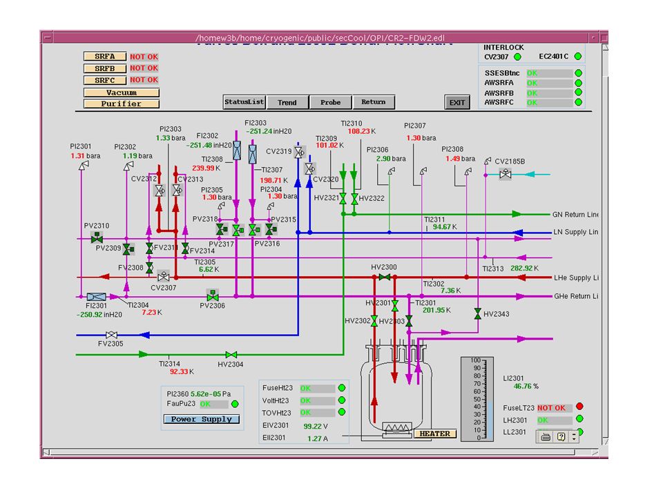
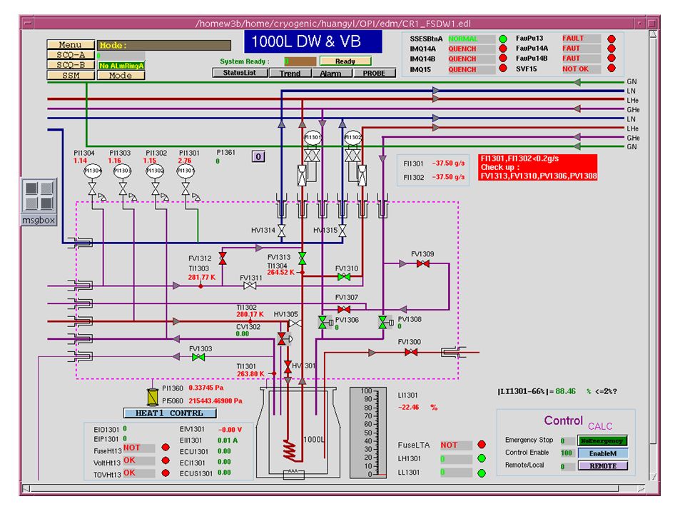
The manufacture of various control valve boxes The various control valve boxes such as SRF control balve box, SCQA/B control valve box and 1000L control dewar valve box were manufactured by the institute of cryogenic and superconductor technology of Harbin. Before transport to IHEP, the cooldown test was done up to the temperature of 100K and the leakage rate is better than 1 10 -10 pa·m 3 /s as well as the function test of control valve, the reading out of temperature sensor and pressure transmiter. The final test of SRF control valve box with LHe temperature has carried out successfully at IHEP and no any abnormal. The cooldown test of 1000L control dewar and valve box with LHe temperature was also carried out successfully at IHEP and the liquid helium was accumulated to 1000L dewar. But ice forming on the neck of dewar during the test that will loss some cooling power. The SCQA/B control valve box are being connecting with SCQ magnets at this stage. The detail will be introduction as the follows.

25
Valve boxes installation

26
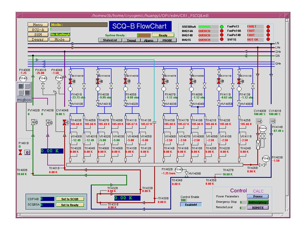
Connection between SCQ valve boxes and SCQ magnets ( 1 ) The SCQ-A/B control valve boxes were transported to cryogenic hall of IHEP on Jan.5, 2006 Discussed the scheme of connection between SCQ valve box and SCQ magnet at IHEP with HIT and BNL people around Jan. 10 to 16,2006. Due to it is difficult to weld the supply pipe of liquid helium with the SC cable inside pipe. So the end can of SC magnet has to be opened. A special support will be designed for open the end can of SC magnets and disassembly the helium supply line from inside end can. The work for SCQ connection from Feb.27 to Mar.18,2006 was the following: – Performed the leak check of SCQ-A/B at cryogenic hall; – Performed the electric insulation check of current leads with the test voltage of 1000V as well as the check of temperature sensor with the test voltage of 500V at cryogenic hall. ( during the check, a 75A current leads of SCQ-B has been breakdown with the voltage of 800V and then it was repaired) –The SCQ-A/B were transported to installation position and start the connection between valve box and magnets –Due to the length of heat shinkable tube form BNL was not enough for connection work. It has to be interrupted. transport
 –The SCQ-A/B were transported to installation position and start the connection between valve box and magnets –Due to the length of heat shinkable tube form BNL was not enough for connection work. It has to be interrupted. transport.")
27
Connection between SCQ valve boxes and SCQ magnets ( 2 ) The work from Apr.5 to present is as follows: –After the completion of the trim of SC cable, make marker for SC cable and voltage tap. The electric insulation check was performed again and a 75A current leads of SCQ-A was breakdown with the voltage of 600V. –After the completed connection of SC cable and helium supply tube of SCQ-B. The final test was performed and it is surprised that the 1200A current leads was breakdown with the voltage of 200V. – After the check in detail, it is found that the bad insulation located at the bellow position of tube. It is guessed that the insulation of cable was broken during the transportation from Harbin to Beijing –Up to now, the connection work still is undergoing. –The final check also include the leak check with the tube pressure of 4.5bara

28
Connection between SCQ valve boxes and SCQ magnets ( 3 )
")
29
Connection between SCQ valve boxes and SCQ magnets ( 4 )
")
30
Connection between SCQ valve boxes and SCQ magnets ( 5 )
")
31
The manufacture of various cryogenic transfer-line The various cryogenic transfer-line such as single channel, four channel and eight channel trasfer-line had been manufactured and installed connection between cryogenic equipment by the cryogenic project group at IHEP. The single channel line is 22 piece and total length about 60m. The four channel is about 15m long and eight 20m long on the side of SC cavity. The single channel line is about 50m include the quench line and about 50m four channel on the side of SC magnet The cooldown test of overall transferline on SC cavity cryogenic side with LHe temerature had been carried out successfully and no any abnormal. The first cooldown test of overall transferline on magnet cryogenic side were carried out and the SSM transferline was cooled down up to LHe temperature. But SCQ transferline only was cooled down to 20K and the leak was observed by vacuum check. The leakage transfer line has been repaired and the second test will be done soon.

32
Flow chart of production Material purchase Sample check 7 elements Pressure test 16bar Passivation cleaning Storage room Production material frock design assembly machining fabrication fixing G10 spacer Dimension check inspection wrapping MLI cleaning connection welding Arc welding leakage check shrinkage test with LN2 leakage check storage room 1 10 -10 pa·m 3 /s Site installation fabrication 、 assembly 、 welding Pressure test 5bar Leakage check Build up insulation vacuum(<1 10 -1 pa) Cooldown test
 Cooldown test")
33
Cryogenic transferline

34
Transferline installation

35
Room of refrigerator A

36
Room of refrigerator B

37
Cryogenic transfer line for SCC operation position

38
The development of cryogenic control system The control of refrigerator was developed by Linde company which is base on the Siemens S7 PLC and communicated with VME/IOC through WinCC/ODK & Ethernet. The control of various control valve box such as SRF, SCQA/B, SSM, 1000L valve box was completed by IHEP cryogenic control group which is based on AB PLC and the EPICS console. The various function check of valve and the read out of temp, Pressure, flow and Level of SRF control valve box and 1000L control valve box have been performed and the cryogenic test has been carried out during commissioning. The function test of SCQA/B and SSMvalve box will be performed soon. The detail will be introduced by control people. At the present, the two control is operated independently except the data share and quench signal interlock for the recovery compressor star up.

39
Structure of Cryogenic Control System

46
The commissioning of cryogenic system with SC cavity dummy load The first commissioning with dummy load was done from Jan 20 to Jan 31. –The SC cavity test station was connected with dummy load, the other two SC cavity operation position were connected with the short of far wary cryogenic transfer-line. – the all transferline,SRF valve box and dummy load were cooled down to the temperature of liquid helium further more the liquid helium was accumulated to dummy load with the level of 80% through the far way cryogenic transferline –The test of control loop were done under cryogenic surrounding such as the level control, heater control and the supply valve control. The second commissioning was carried out from Feb.20 to Mar.20. –Measured the pressure stability in the LHe vessel of dummy load –Measured the level stability in LHe vessel of dummy load. –Simulated the RF loss by other heater. –Optimized the PID parameters –Tested the action of first class safety valve of 0.26bar. –Tested the interlock of heater, level etc.

47
Cooldown curve

48
The liquid helium level accumulation in 2000L dewar

49
Warm up curve

50
The test result of pressure stability in LHe vessel Red line: pressure Date and Time: Mar.16,2006 11:13am to 15:13pm Stability: less than ±3mbar

51
The test result of liquid helium level stability 第二项:超导腔假负载内液氦的液面稳定性测试 设计要求:超导腔内液面稳定度为 ±1% 测试结果:液面稳定度优于 ±1 %(见图 2 ) Blue line: liquid helium level Date and Time: Mar.16,2006 11:13 to 15:13 Level stability: less than ±1 %。
 Blue line: liquid helium level Date and Time: Mar.16, :13 to 15:13 Level stability: less than ±1 %。")
52
The compensation of RF loss (1) Simulated the compensation of RF loss by heater 5W/step, RF loss from 0W to 50W. The total heat load still keep 100W. The pressure and LHe level are still stable during this test.

53
The compensation of RF loss (2) Simulated the compensation of RF loss by heater RF loss from 50W to 0W suddenly. The total heat load still keep 100W. The pressure and LHe level are still stable during this test.

54
The further work of cryogenic system (1) The SCQA/B connection will be completed on May.3,2006 The second cryogenic transfer-line cooldown test of magnets side will be completed on May.6,2006 The preparation of SCQ magnets cooldown test will be completed on Jun.12,2006 –Connection cryogenic tube with SCQ valve boxes –Quench tube installation and connection with SCQ –The installation of cooling current leads helium tube and connection between valve boxes and mass flow controller. – Room temperature test of SCQ valve boxes control system –Purge the SCQ cryogenic system The commissioning of SCQ cryogenic system will be completed on Jul.10,2006 Keep the steady status operation for magnets field measurement until Sep.1,2006

55
The further work of cryogenic system (2) The real SC cavity will be cooled down test at the test station in the early of next month and then the dummy load will be tested at the east operation position. Due to the delay, the SSM valve box and magnet will has to be cooled down test after SCQ test according present plan. The cryogenic transfer-line of SCQ magnets at off line position will be manufactured and completed in the July,2006 for the spare scheme test of SCQ/SSM

56
Summary Too tight schedule for the construction and commissioning of cryogenic system We have got a little “cryogenic” feeling and valuable experience during cryogenic system commissioning BEPCII cryogenic works need still pay out the more and more efforts.

57
That is all. Thanks for your attention!

Similar presentations


.>")


