Download presentation
Presentation is loading. Please wait.

1
MARINE PUMPING SYSTEM

2
SPECIFIC LEARNING OBJECTIVES:
At the end of this topic you are expected to learn: Principles of Marine Pumping Systems State the function of a pump Describe the three requirements for a pump to transfer fluids List the losses of head in a pumping system Explain the requirement for viscosity of the fluid for pump design

3
Explain the requirement for permission before any fluid is transferred onboard

4
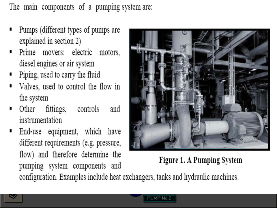
Pumping System have two main purposes:
Transfer of liquid from one place to another place (e.g. water from an underground aquifer into a water storage tank) Circulate liquid around a system (e.g. cooling water or lubricants through machines and equipment)
 Circulate liquid around a system (e.g. cooling water or lubricants through machines and equipment)")
10
PUMP A pump is a device used to move fluids, such as liquids, gases or slurries. A pump displaces a volume by physical or mechanical action. Pumps fall into three major groups: direct lift, displacement, and gravity pumps.[1] Their names describe the method for moving a fluid.

11
PUMP Def’n: device that uses an external power source to apply force to a fluid in order to move it from one place to another Must overcome: (1) frictional forces from large quantities of fluid (2) difference in static pressure between two locations Must provide any velocity desired
 frictional forces from large quantities of fluid. (2) difference in static pressure between two locations. Must provide any velocity desired.")
12
MARINE PUMP A device use aboardship which adds energy to a liquid or gas to overcome resistance or system losses causing it to generate pressure and perhaps movement of a fluid A machine used to raise fluid from a low point to a high point

13
Engine – a device for converting thermal energy of working substance into useful mechanical work
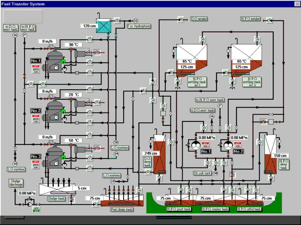
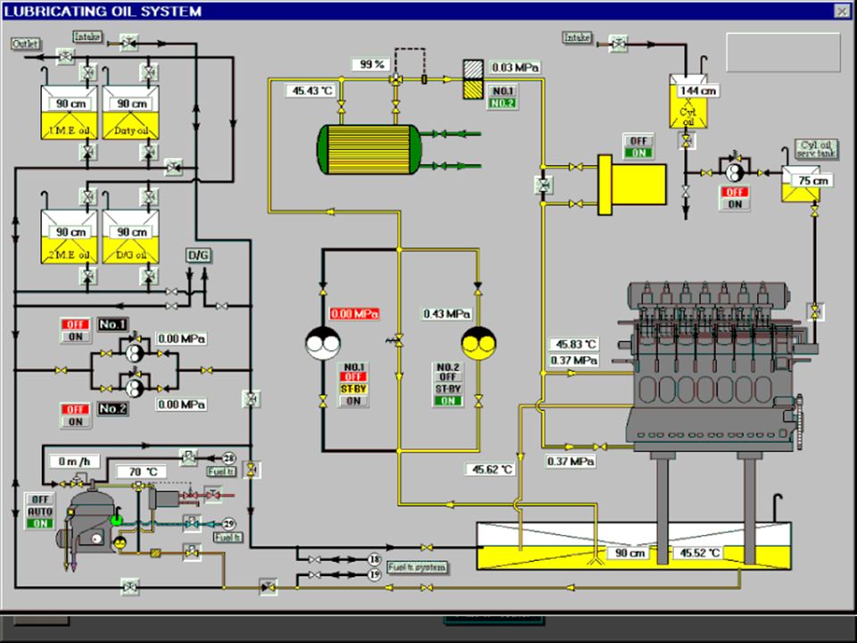
Marine pumps generally handle fuel oil, lubricating oil, condensate and boiler feed, circulation water or coolant, ballast and bilge water, air, etc. though pumps delivering air are generally called blowers or compressors. Special liquid cargoes of nearly or any sort may be handled by a suitable pump. Depending upon the types of installation, pumps are driven by steam engines, steam, electric motors, Diesel engines and air.

14
Pumps can also be found coupled with engine it supports
Pumps can also be found coupled with engine it supports. Motive power is selected for reasons of safety, economics or convenience.

15
Fluid Properties The properties of the fluids being pumped can significantly affect the choice of pump. Key considerations include: Acidity/alkalinity (pH) and chemical composition. Corrosive and acidic fluids can degrade pumps, and should be considered when selecting pump materials. Operating temperature. Pump materials and expansion, mechanical seal components, and packing materials need to be considered with pumped fluids that are hotter than 200°F. Solids concentrations/particle sizes. When pumping abrasive liquids such as industrial slurries, selecting a pump that will not clog or fail prematurely depends on particle size, hardness, and the volumetric percentage of solids.
 and chemical composition. Corrosive and acidic fluids can degrade pumps, and should be considered when selecting pump materials. Operating temperature. Pump materials and expansion, mechanical seal components, and packing materials need to be considered with pumped fluids that are hotter than 200°F. Solids concentrations/particle sizes. When pumping abrasive liquids such as industrial slurries, selecting a pump that will not clog or fail prematurely depends on particle size, hardness, and the volumetric percentage of solids.")
16
Fluid Properties Specific gravity. The fluid specific gravity is the ratio of the fluid density to that of water under specified conditions. Specific gravity affects the energy required to lift and move the fluid, and must be considered when determining pump power requirements. Vapor pressure. A fluid’s vapor pressure is the force per unit area that a fluid exerts in an effort to change phase from a liquid to a vapor, and depends on the fluid’s chemical and physical properties. Proper consideration of the fluid’s vapor pressure will help to minimize the risk of cavitation.

17
Fluid Properties Viscosity. The viscosity of a fluid is a measure of its resistance to motion. Since kinematic viscosity normally varies directly with temperature, the pumping system designer must know the viscosity of the fluid at the lowest anticipated pumping temperature. High viscosity fluids result in reduced centrifugal pump performance and increased power requirements. It is particularly important to consider pump suction-side line losses when pumping viscous fluids.

18
3 REQUIREMENTS OF A PUMP TO TRANSFER FLUID
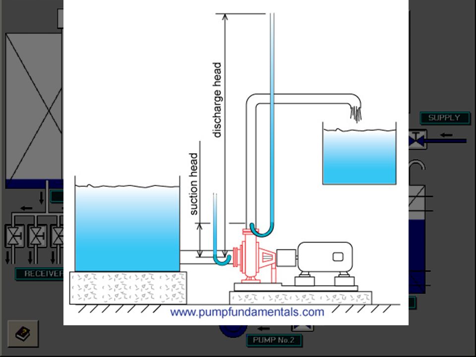
A marine pumping system on a ship consists of: Suction piping Pump Discharge piping The system is arranged to provide a positive pressure or head at some point and discharge the liquid. The pump provides the energy to develop the head and overcome any losses in the system. The rate of flow at a certain head is called duty point.

19
PUMP HEAD Head is a measure of resistance to flow. If a pump has a maximum output of 20 head feet, it means it can pump water 20' straight in the air. If a pump is rated at 50 gallons per minute at 10 feet it means it can overcome 10 feet of head (TDH) and still deliver 50 GPM. As you increase the head, you decrease the flow rate, and increase your operating costs. To maximize your flow, you must minimize your head, which also minimizes your operating costs.
 and still deliver 50 GPM. As you increase the head, you decrease the flow rate, and increase your operating costs. To maximize your flow, you must minimize your head, which also minimizes your operating costs.")
20
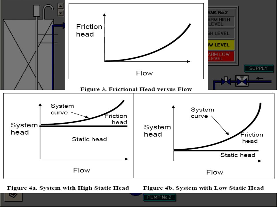
3 MAIN SOURCES OF HEAD: Static Head - This is the vertical distance you raise the water. To determine your static head, measure from the surface of the tank (vertically), to the highest point in the discharge line where the water is discharged to the atmosphere.
, to the highest point in the discharge line where the water is discharged to the atmosphere.")
21
3 MAIN SOURCES OF HEAD: Friction Head - As water flows through pipe and fittings there is resistance. The higher the flow and/or the smaller the pipe, the higher the resistance. Determine your overall pipe length, including adding in the equivalent length for your fittings. Consult the friction loss chart. Find where the column for your pipe diameter intersects the row for your flow rate and read the friction loss per 100' pipe. Use large enough pipe to minimize friction loss. It is usually best to keep your friction loss (per 100 feet of pipe) to less than 6 feet. In other words, once you know the desired flow rate, pick a pipe diameter, or schedule, that will give you less than 6 feet of friction loss per 100 feet of pipe. (Friction Loss and Fittings Loss)
 to less than 6 feet. In other words, once you know the desired flow rate, pick a pipe diameter, or schedule, that will give you less than 6 feet of friction loss per 100 feet of pipe. (Friction Loss and Fittings Loss)")
23
3 MAIN SOURCES OF HEAD: Pressure Head - Any additional pressure required by filters, spray nozzles, etc. must be calculated. The conversion is 1 PSI = 2.31 head feet. - Atmospheric pressure: usually refers to the pressure in the local environment of the pump. Atmospheric pressure varies with elevation, it is 14.7 psi at sea level and decreases with rising elevation. If our filter runs at 10 PSI, that would add 23.1 feet of head to the 17.9 feet required to overcome the friction loss of our pipe and fittings. So now the total pump head is 41 feet without considering the static head. (Notice that the pump head will increase as the filter gets dirty and increases the back pressure.)
")
24
3 MAIN SOURCES OF HEAD: Total dynamic head ( TDH) – Sum of static head, friction loss head, fittings loss head, and pressure head. Type of head Source Calculation PH in Feet Static Head Elevated Pipe 10' - above surface of water 10.0 Pipe Loss 2" Pipe 8.12' per 100 feet of pipe 13.0 Fittings Loss 6' per elbow 10x 2" 90° elbows = 60 ft 4.9 Pressure Head Filter running at 10 psi x 2.31 23.1 Total Pump head in feet 51.0

25
3 MAIN SOURCES OF HEAD: Don't forget to add up the equivalent feet of pipe for all the fittings. Now that you know your flow and head, you can select a pump that provides this performance, and does so efficiently.

26
Losses of Head in Pumping System
Power supplied to the pump must take into account the various losses. These are made up of: Friction Loss in bearings and glands, surfaces of impeller and casing. Impellers should be highly polished to minimize friction loss. Head Loss in pump due to shock at each entry and exit to impeller vane where eddies are formed at vane edges. Leakage loss in thrust balance devices, gland sealing, clearances between cutwater and casing and bearing seals.

27
Requirement for Viscosity of the Fluid for Pump
Viscosity - the property of a fluid or semifluid that causes it to resist flowing Oil are much more difficult for pumps to handle than water. Losses increase within the pump and pump lines. Both head and capacity are reduced; therefore more power is required for operation. Both hot and thick liquids should flow to the pump under a positive suction head (flow by gravity) for satisfactory operation. The pump will then be kept properly primed in the case of thick liquids; vaporization and vapour binding will be avoided in the case of hot liquids.
 for satisfactory operation. The pump will then be kept properly primed in the case of thick liquids; vaporization and vapour binding will be avoided in the case of hot liquids.")
28
Requirement for Viscosity of the Fluid for Pump
The problem of lifting a hot liquid is often difficult. The hotter the liquid, the lower will be the maximum possible suction lift. Water boils at 100 C atmospheric pressure. Under the partial vacuum that exists in the feed pipe, the boiling point is lower. Part of the hot water may vaporize causing vapour binding in the pump. In some cases the water vaporizes and expands sufficiently to destroy the vacuum thereby, stops the effectiveness of pumping.

29
Requirement for Viscosity of the Fluid for Pump
When pumping hot oil, it may happen that a small amount of water entrained in the oil may flash (boil) and interrupt the pumping operation. This can be serious in the case of a fuel oil service pump, as it may cause a “flare back” from the boilers. Providing an air chamber on the discharge line which will maintain a pressure while the pump is compressing the vapour in the line, can guard this against other precautions may be taken.
 and interrupt the pumping operation. This can be serious in the case of a fuel oil service pump, as it may cause a flare back from the boilers. Providing an air chamber on the discharge line which will maintain a pressure while the pump is compressing the vapour in the line, can guard this against other precautions may be taken.")
30
Requirement for Viscosity of the Fluid for Pump
Here is what is going to change when you pump viscous fluids with a centrifugal pump: The brake horsepower requirement will increase. You will notice a reduction in the head the pump will produce. Some reduction in capacity will occur with moderate and high viscosities. The pump's efficiency will decrease.

31
Requirement for Viscosity of the Fluid for Pump
High viscosity fluids are better handled with positive displacement pumps that are affected differently than centrifugal pumps by a change in fluid viscosity: At a constant speed, changes in viscosity will have very little affect on capacity. The total head will probably increase with viscosity because of higher system resistance. The brake horsepower (kilowatts) will increase with capacity. The efficiency probably will not be affected because of less leakage through the internal pump clearances. In some cases the efficiency will increase
 will increase with capacity. The efficiency probably will not be affected because of less leakage through the internal pump clearances. In some cases the efficiency will increase.")
34
Pre-Bunker Checklist:
Pre-Bunkering Procedure: 1. State of adjacent waters noticed 2. Vessel properly secured to dock 3. Check suppliers product corresponds to ordered product 4. Agree quantity to be supplied 5. Check valves open 6. Day tanks full and supply valves closed 7. Warning signs in position e.g. No Smoking 8. SOPEP plan available

35
9. Clean up material in place
10. Oil Boom in place 11. Foam fire extinguisher placed at bunker station 12. Alfa Laval and transfer pumps off 13. Fuel tank supply valves open 14. Agree stop/start signals between vessel and barge/truck 15. Bravo flag flying/red light showing 16. Agree pumping/transfer rate 17. Agree emergency shut down procedure 18. Specification sheet received

36
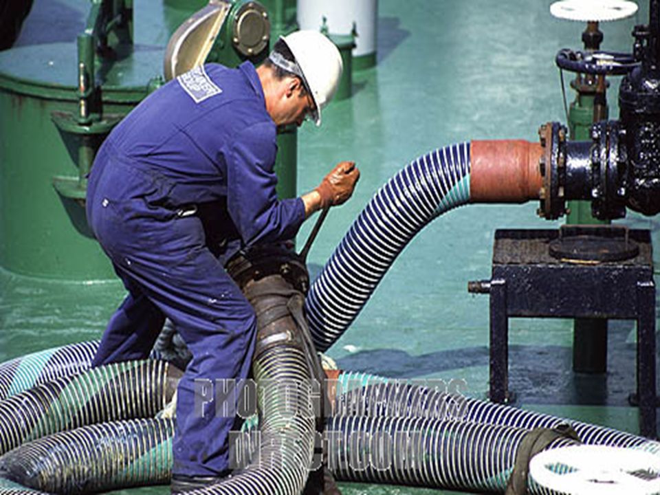
19. Check hose and couplings are secure and in good order 20
19. Check hose and couplings are secure and in good order 20. Fuel nozzle and hose secured to vessel 21. Check barge/truck meters Reading: 22. Check on board meters Reading: 23. Bunker Valve open 24. Unused manifold connections blanked off 25. Master informed 26. Signal pumping to commence The above checklist has to be completely filled legibly by both the ship & barge personnels.

37
SOPEP equipments At the bunker manifold and wherever necessary, as per the ships SOPEP plan, the SOPEP equipments should be kept in immediate readiness in order to avoid oil spill/pollution during bunkering operation.

38
SOPEP- Shipboard Oil Pollution Emergency Plan.
The SOPEP Locker must have minimum of the below specified items: 1. absorbent roll 2. absorbent pads 3. absorbent granules 4. absorbent materials 5. brooms 6. shovels 7. mops 8. scoops 9. empty receptacles (200 ltrs capacity) 10. portable air driven pumps 11. oil boom 12. oil spill dispersants.
 10. portable air driven pumps. 11. oil boom. 12. oil spill dispersants.")
39
During Bunkering Procedures:
During Bunkering checklist: 1. Witness taking and sealing of 2 representative product samples 2. Monitor fuel connections for leaks fuel flow and control tank levels 3. Change over of tanks whenever necessary. 4. Checking the rate at which bunkers are received. 5. Checking the tightness/slackness of mooring ropes. 6. Checking trim/list of the bunker barge & the ship. 7. Continuous monitoring/look outs for the vessel's position(when at anchor). During bunkering, the above checklist must be filled up and continuous monitoring of the above specified items are required till the bunkering operation is complete.
. During bunkering, the above checklist must be filled up and continuous monitoring of the above specified items are required till the bunkering operation is complete.")
40
After Bunkering Procedures:
On completion of the bunkering operations, with the ship-barge co-ordination, the line should be blown with air to make sure the line is not filled with oil. The after-bunker checklist is followed. After Bunker Checklist: 1. Bunker Valve closed 2. Disconnect hose (drain before disconnecting) 3. Check barge/truck meter Reading: 4. Check ships meter Reading:
 3. Check barge/truck meter Reading: 4. Check ships meter Reading:")
41
5. Sign Bunker Delivery Receipt BDR No.:(Bunker Delivery Report/Note).
6. Retain BDR with product sample 7. SOPEP plan returned to bridge 8. Clean up gear stowed / Oil boom returned 9. Bravo Flag/Red light stowed/switched off 10. Remove and pack away warning/safety signs 11. Foam fire extinguisher placed back in correct location 12. Complete Oil Record Book 13. Master informed of completion 14. Confirm in Oil Record Book Bunkering checklist completed

42
END OF PRESENTATION

43
Glossary in Pumps and Pumping System
Fluid - any substance that undergoes a change in pressure, temperature or volume used as means to carry out a thermodynamic process or cycle Cavitation: the collapse of bubbles that are formed in the eye of the impeller due to low pressure. The implosion of the bubbles on the inside of the vanes creates pitting and erosion that damages the impeller. The design of the pump, the pressure and temperature of the liquid that enters the pump suction determines whether the fluid will cavitate or not.

44
Glossary in Pumps and Pumping System
Centrifugal force: A force associated with a rotating body. In the case of a pump, the rotating impeller pushes fluid on the back of the impeller blade, imparting circular and radial motion. A body that moves in a circular path has a centrifugal force associated with it . Dead head: a situation that occurs when the pump's discharge is closed either due to a blocage in the line or an inadvertently closed valve. At this point, the pump will go to it's maximum shut-off head, the fluid will be recirculated within the pump resulting in overheating and possible damage. Diffuser: located in the discharge area of the pump, the diffuser is a set of fixed vanes often an integral part of the casing that reduces turbulence by promoting a more gradual reduction in velocity.

45
Glossary in Pumps and Pumping System
Efficiency:: the efficiency of a pump can be determined by measuring the torque at the pump shaft with a torque meter and then calculating the efficiency based on the speed of the pump, the pressure or total head and flow produced by the pump. The standard equation for torque and speed provides power. Absolute pressure: pressure is measured in psi (pounds per square inch) in the imperial system and kPa (kiloPascal or bar) in the metric system. Most pressure measurements are made relative to the local atmospheric pressure. In that case we add a "g" to the pressure measurement unit such as psig or kPag. The value of the local atmospheric pressure varies with elevation.
 in the imperial system and kPa (kiloPascal or bar) in the metric system. Most pressure measurements are made relative to the local atmospheric pressure. In that case we add a g to the pressure measurement unit such as psig or kPag. The value of the local atmospheric pressure varies with elevation.")
46
Glossary in Pumps and Pumping System
It is not the same if you are at sea level (14.7 psia) or at 4000 feet elevation (12.7 psia). In certain cases it is necessary to measure pressure values that are less then the local atmospheric pressure and in those cases we use the absolute unit of pressure, the psia or kPa a. pa(psia) = pr(psig) + patm(psia), patm = 14.7 psia at sea level. where pa is the absolute pressure, pr the relative pressure and patm the absolute pressure value of the local atmospheric pressure.
 or at 4000 feet elevation (12.7 psia). In certain cases it is necessary to measure pressure values that are less then the local atmospheric pressure and in those cases we use the absolute unit of pressure, the psia or kPa a. pa(psia) = pr(psig) + patm(psia), patm = 14.7 psia at sea level. where pa is the absolute pressure, pr the relative pressure and patm the absolute pressure value of the local atmospheric pressure.")
47
Glossary in Pumps and Pumping System
Accumulator: used in domestic water applications to stabilize the pressure in the system and avoid the pump cycling on and off every time a tap is opened somewhere in the house. Affinity laws: the affinity laws are used to predict the change in diameter required to increase the flow or total head of a pump. They can also predict the change in speed required to achieve a different flow and total head. The affinity laws can only be applied in circumstances where the system has a high friction head compared to the static head and this is because the affinity laws can only be applied between performance points that are at the same efficiency. Axial flow pump: refers to a design of a centrifugal pump for high flow and low head. The impeller shape is similar to a propeller. The value of the specific speed number will provide an indication whether an axial flow pump design is suitable for your application

48
Glossary in Pumps and Pumping System
Baseplate: all pumps require some sort of steel base that holds the pump and motor and is anchored to a concrete base. Best Efficiency Point (B.E.P.): The point on a pump's performance curve that corresponds to the highest efficiency. At this point, the impeller is subjected to minimum radial force promoting a smooth operation with low vibration and noise. Bingham plastic: A fluid that behaves in a Newtonian fashion (i.e. constant viscosity) but requires a certain level of stress to set it in motion. Bourdon pressure gauge: the Bourdon tube is a sealed tube that deflects in response to applied pressure and is the most common type of pressure sensing mechanism.
: The point on a pump s performance curve that corresponds to the highest efficiency. At this point, the impeller is subjected to minimum radial force promoting a smooth operation with low vibration and noise. Bingham plastic: A fluid that behaves in a Newtonian fashion (i.e. constant viscosity) but requires a certain level of stress to set it in motion. Bourdon pressure gauge: the Bourdon tube is a sealed tube that deflects in response to applied pressure and is the most common type of pressure sensing mechanism.")
49
Glossary in Pumps and Pumping System
Check valve: a device for preventing flow in the reverse direction. The pump should not be allowed to turn in the reverse direction as damage and spillage may occur. Check valves are not used in certain applications where the fluid contains solids such as pulp suspensions or slurries as the check valve tends to jam. A check valve with a rapid closing feature is also used as a preventative for water hammer. Chopper pump: a pump with a serrated impeller edge which can cut large solids and prevent clogging. Closed or open impeller: the impeller vanes are sandwiched within a shroud which keeps the fluid in contact with the impeller vanes at all times. This type of impeller is more efficient than an open type impeller. The disadvantage is that the fluid passages are narrower and could get plugged if the fluid contains impurities or solids.

50
Glossary in Pumps and Pumping System
CV coefficient: a coefficient developed by control valve manufacturers that provides an indication of how much flow the valve can handle for a 1 psi pressure drop. For example, a control valve that has a CV of 500 will be able to pass 500 gpm with a pressure drop of 1 psi. CV coefficients are sometimes used for other devices such as check valves. Cutwater: the narrow space between the impeller and the casing in the discharge area of the casing. Diaphragm pump: a positive displacement pump. Double Diaphragm pumps offer smooth flow, reliable operation, and the ability to pump a wide variety of viscous, chemically aggressive, abrasive and impure liquids. They are used in many industries such as mining, petro-chemical, pulp and paper and others.

51
Glossary in Pumps and Pumping System
Dilatant: The property of a fluid whose viscosity increases with strain or displacement. Double suction pump: the liquid is channeled inside the pump casing to both sides of the impeller. This provides a very stable hydraulic performance because the hydraulic forces are balanced. The impeller sits in the middle of the shaft which is supported on each end by a bearing Double volute pump: a pump where the immediate volute of the impeller is separated by a partition from the main body of the casing. This design reduces the radial load on the impeller making the pump run smoother and vibration free.

52
Glossary in Pumps and Pumping System
Drooping curve: similar to the normal profile except at the low flow end where the head rises then drops as it gets to the shut-off head point. End suction pump: a typical centrifugal pump, the workhorse of industry. Also known as volute pump, standard pump, horizontal suction pump. The back pull out design is a standard feature and allows easy removal of the impeller and shaft with the complete drive and bearing assembly while keeping the piping and motor in place. Expeller: a hydro-dynamic seal that provides a seal without addition of water to the gland, specially useful for liquid slurries.

53
Glossary in Pumps and Pumping System
External Gear pump: a positive displacement pump. Two spur gears are housed in one casing with close clearance. Liquid is trapped between the gear tooth spaces and the casing, the rotation of the gears pumps the liquid. They are also used for high pressure industrial transfer and metering applications on clean, filtered, lubricating fluids. Foot valve: a check valve that is put on the end of the pump suction pipe, often accompanied with an integrated strainer. Head: the height at which a pump can displace a liquid to. Head is also a form of energy. In pump systems there are 4 different types of head: elevation head or static head, pressure head, velocity head and friction head loss.

54
Glossary in Pumps and Pumping System
Hydraulic gradient: All the energy terms of the system ( for example velocity head and piping and fitting friction loss) are converted to head and graphed above an elevation drawing of the installation. It helps to visualize where all the energy terms are located and ensure that nothing is missed. Impeller: The rotating element of a pump which consists of a disk with curved vanes. The impeller imparts movement and pressure to the fluid. Impeller eye: that area of the centrifugal pump that channels fluid into the vane area of the impeller. The diameter of the eye will control how much fluid can get into the pump at a given flow rate without causing excessive pressure drop and cavitation.
 are converted to head and graphed above an elevation drawing of the installation. It helps to visualize where all the energy terms are located and ensure that nothing is missed. Impeller: The rotating element of a pump which consists of a disk with curved vanes. The impeller imparts movement and pressure to the fluid. Impeller eye: that area of the centrifugal pump that channels fluid into the vane area of the impeller. The diameter of the eye will control how much fluid can get into the pump at a given flow rate without causing excessive pressure drop and cavitation.")
55
Glossary in Pumps and Pumping System
Hydraulic gradient: All the energy terms of the system ( for example velocity head and piping and fitting friction loss) are converted to head and graphed above an elevation drawing of the installation. It helps to visualize where all the energy terms are located and ensure that nothing is missed. Impeller: The rotating element of a pump which consists of a disk with curved vanes. The impeller imparts movement and pressure to the fluid. Impeller eye: that area of the centrifugal pump that channels fluid into the vane area of the impeller. The diameter of the eye will control how much fluid can get into the pump at a given flow rate without causing excessive pressure drop and cavitation.
 are converted to head and graphed above an elevation drawing of the installation. It helps to visualize where all the energy terms are located and ensure that nothing is missed. Impeller: The rotating element of a pump which consists of a disk with curved vanes. The impeller imparts movement and pressure to the fluid. Impeller eye: that area of the centrifugal pump that channels fluid into the vane area of the impeller. The diameter of the eye will control how much fluid can get into the pump at a given flow rate without causing excessive pressure drop and cavitation.")
56
Glossary in Pumps and Pumping System
Inducer: an inducer is a device attached to the impeller eye that is usually shaped like a screw that helps increase the pressure at the impeller vane entrance and make viscous or liquids with high solids pumpable. Internal gear pump: a positive displacement pump invented by Jens Nielsen, one of the founders of Viking Pump. It uses two rotating gears which un-mesh at the suction side of the pump to create voids which allow atmospheric pressure to force fluid into the pump. The spaces between the gear teeth transport the fluid on either side of a crescent to the discharge side, and then the gears re-mesh to discharge the fluid.

57
Glossary in Pumps and Pumping System
Jet pump: a jet pump is a commonly available residential water supply pump. It has an interesting clever design that can lift water from a well (up to 25 feet) and allow it to function without a check valve on the suction and furthermore does not require priming. The heart of the design is a venturi (source of water is from the discharge side of the impeller) that creates low pressure providing a vacuum at the suction and allowing the pump to lift fluids. Laminar: A distinct flow regime that occurs at low Reynolds number (Re <2000). It is characterized by fluid particles in layers moving past one another without mixing.
 and allow it to function without a check valve on the suction and furthermore does not require priming. The heart of the design is a venturi (source of water is from the discharge side of the impeller) that creates low pressure providing a vacuum at the suction and allowing the pump to lift fluids. Laminar: A distinct flow regime that occurs at low Reynolds number (Re <2000). It is characterized by fluid particles in layers moving past one another without mixing.")
58
Glossary in Pumps and Pumping System
Lobe pump: a positive displacement pump. Primarily used in food applications because they handle solids without damaging them. Lobes are driven by external timing gears as a result the lobes do not make contact. Liquid travels around the interior of the casing in the pockets between the lobes and the casing, meshing of the lobes forces liquid through the outlet port under pressure. Mechanical seal: a name for the joint that seals the fluid in the pump stopping it from coming out at the joint between the casing and the pump shaft. Net Positive Suction Head Available (N.P.S.H.A.): Net positive suction head available. The head or specific energy at the pump suction flange less the vapor pressure head of the fluid.
: Net positive suction head available. The head or specific energy at the pump suction flange less the vapor pressure head of the fluid.")
59
Glossary in Pumps and Pumping System
Net Positive Suction Head Required (N.P.S.H.R.): Net positive suction head required. The manufacturers estimate on the NPSH required for the pump at a specific flow, total head, speed and impeller diameter. This is determined my measurement. Newtonian fluid: A fluid whose viscosity is constant and independent of the rate of shear (strain). For Newtonian fluids, there is a linear relationship between the rate of shear and the tangential stress between layers. Operating point: The point (flow rate and total head) at which the pump operates. It is located at the intersection of the system curve and the performance curve of a pump. It corresponds to the flow and head required for the process.
: Net positive suction head required. The manufacturers estimate on the NPSH required for the pump at a specific flow, total head, speed and impeller diameter. This is determined my measurement. Newtonian fluid: A fluid whose viscosity is constant and independent of the rate of shear (strain). For Newtonian fluids, there is a linear relationship between the rate of shear and the tangential stress between layers. Operating point: The point (flow rate and total head) at which the pump operates. It is located at the intersection of the system curve and the performance curve of a pump. It corresponds to the flow and head required for the process.")
60
Glossary in Pumps and Pumping System
Peripheral pump: also known as regenerative or regenerative turbine pump. These are low capacity (150 gpm or 34 m3/h) high head (5400 ft or 1645 m) pumps. The impeller has short vanes at the periphery and these vanes pass through an annular channel. The fluid enters between two impeller vanes and is set into a circular motion, this adds energy to the fluid particles which travel in a spiral like path from the inlet to the outlet. Each set of vanes continuously adds energy to the fluid particles. Performance curve: A plot of Total Head vs. flow for a specific pump model, impeller diameter and speed (syn characteristic curve, water performance curve)
 high head (5400 ft or 1645 m) pumps. The impeller has short vanes at the periphery and these vanes pass through an annular channel. The fluid enters between two impeller vanes and is set into a circular motion, this adds energy to the fluid particles which travel in a spiral like path from the inlet to the outlet. Each set of vanes continuously adds energy to the fluid particles. Performance curve: A plot of Total Head vs. flow for a specific pump model, impeller diameter and speed (syn characteristic curve, water performance curve)")
61
Glossary in Pumps and Pumping System
Pipe roughness: A measurement of the average height of peaks producing roughness on the internal surface of pipes. Roughness is measured in many locations and then averaged, it is usually defined in micro-inches RMS (root mean square). Piping pressure (maximum): it may be necessary in certain applications to check the maximum rating of your pipes to avoid bursting due to excessive pressure. The ASME pressure piping code B31.3 provides the maximum stress for pipes of various materials. Pitot pump: also know as rotating casing pump. This pump’s specialty is low to medium flow rates at high pressures. It is frequently used for high pressure shower supply on paper machines.
. Piping pressure (maximum): it may be necessary in certain applications to check the maximum rating of your pipes to avoid bursting due to excessive pressure. The ASME pressure piping code B31.3 provides the maximum stress for pipes of various materials. Pitot pump: also know as rotating casing pump. This pump’s specialty is low to medium flow rates at high pressures. It is frequently used for high pressure shower supply on paper machines.")
62
Glossary in Pumps and Pumping System
Pressure: The application of a force to a body producing more or less compression within the liquid. In a static fluid pressure varies with height. Pressure head: an expression of energy, specifically it is energy per unit weight of fluid displaced. Progressive cavity pump: a positive displacement pump. These pumps are ideal for fluids that are just too tough for other pumps to handle. e.g. – pastes, greases, sludge etc. They consist of only one driven metal rotor rotating within an elastomer lined (elastic) stator. Pseudoplastic: The property of a fluid whose viscosity increases slowly with rate of shear.
 stator. Pseudoplastic: The property of a fluid whose viscosity increases slowly with rate of shear.")
63
Glossary in Pumps and Pumping System
Pumps as turbines (PAT): Pumps used in reverse to act as turbines. Radial flow pump: refers to the design of a centrifugal pump for medium head and medium flow or high head and low flow. The value of the specific speed number will provide an indication whether a radial pump design is suitable for your application. Radial vane pump: also known as partial emission pump or vane pump. A frame mounted, end suction, top centerline discharge, ANSI pump designed specifically to handle corrosive chemicals at low flows. Recessed impeller pump: sometimes known as vortex pump. This is a frame-mounted, back pull-out, end suction, recessed impeller, tangential discharge pump designed specifically to handle certain bulky or fibrous solids, air or gas entrained liquids or shear sensitive liquids.
: Pumps used in reverse to act as turbines. Radial flow pump: refers to the design of a centrifugal pump for medium head and medium flow or high head and low flow. The value of the specific speed number will provide an indication whether a radial pump design is suitable for your application. Radial vane pump: also known as partial emission pump or vane pump. A frame mounted, end suction, top centerline discharge, ANSI pump designed specifically to handle corrosive chemicals at low flows. Recessed impeller pump: sometimes known as vortex pump. This is a frame-mounted, back pull-out, end suction, recessed impeller, tangential discharge pump designed specifically to handle certain bulky or fibrous solids, air or gas entrained liquids or shear sensitive liquids.")
64
Glossary in Pumps and Pumping System
Recirculation: at low flow and high flow compared to the flow at the B.E.P. the fluid will start to recirculate or move in a reverse direction at the suction and at the discharge. Reynolds number: the Reynolds number is proportional to the ratio of velocity and viscosity, the higher the number (higher than 4000 for turbulent flow) the more turbulent the flow and the less viscosity has an effect. Screw impeller: The screw centrifugal impeller is shaped like a tapered Archimedes screw. Originally developped for pumping live fish, the screw centrifugal pump has become popular for many solids handling applications. Self-priming pump: a pump that does not require priming or a initial filling with liquid. The pump casing carries a reserve of water that helps create a vacuum that will lift the fluid from a low source.
 the more turbulent the flow and the less viscosity has an effect. Screw impeller: The screw centrifugal impeller is shaped like a tapered Archimedes screw. Originally developped for pumping live fish, the screw centrifugal pump has become popular for many solids handling applications. Self-priming pump: a pump that does not require priming or a initial filling with liquid. The pump casing carries a reserve of water that helps create a vacuum that will lift the fluid from a low source.")
65
Glossary in Pumps and Pumping System
Shut-off head: The Total Head corresponding to zero flow on the pump performance curve. Side channel pump: is a pump that provides high head at low flows with the added benefit of being able to handle gases. Siphon: A system of piping or tubing where the exit point is lower than the entry point and where some part of the piping is above the free surface of the fluid source. Sludge pump: certain types of sludges tend to settle very quickly and are hard to keep in suspension Slurry pump: a rugged heavy duty pump intended for aggressive or abrasive slurry solutions typically found in the mining industry with particles of various sizes. It achieves this by lining the inside of the pump casing as well as the impeller with rubber.

66
Glossary in Pumps and Pumping System
Specific gravity (SG): the ratio of the density of a fluid to that of water at standard conditions. If the SG is 1 then the density is the same as water, if it is less than 1 then the fluid is less dense than water and heavier than water if the SG is bigger than 1. Mercury has an SG of 14, gasoline has an SG of 0.8. The usefulness of specific gravity is that it has no units since it is a comparative measure of density or a ratio of densities therefore specific gravity will have the same value no matter what system of units we are using Specific speed: a number that provides an indication what type of pump (for example radial, mixed flow or axial) is suitable for the application.
: the ratio of the density of a fluid to that of water at standard conditions. If the SG is 1 then the density is the same as water, if it is less than 1 then the fluid is less dense than water and heavier than water if the SG is bigger than 1. Mercury has an SG of 14, gasoline has an SG of 0.8. The usefulness of specific gravity is that it has no units since it is a comparative measure of density or a ratio of densities therefore specific gravity will have the same value no matter what system of units we are using. Specific speed: a number that provides an indication what type of pump (for example radial, mixed flow or axial) is suitable for the application.")
67
Glossary in Pumps and Pumping System
Standard volute pump close coupled: The volute is the casing which has a spiral shape. The motor shaft is connected to the impeller without an intermediate coupling providing a compact arrangement. The flow range is typically less than 300 gpm. Standard volute pump separately coupled: The volute is the casing which has a spiral shape. The motor shaft is connected to the impeller with an intermediate shaft with two couplings. Stuffing box: the joint that seals the fluid in the pump stopping it from coming out between the casing and the pump shaft. Submersion: Submersion as used here is the height between the free surface of a suction tank and the pump intake pipe. Suction flow splitter: a rib of metal across the pump suction that is installed on certain pumps. It's purpose is to remove large scale vortexes so that the stream lines are as parallel as possible as the fluid enters the impeller eye.

68
Glossary in Pumps and Pumping System
Suction guide: a device that helps straighten the flow ahead of a pump that has a 90 degree elbow immediately ahead of it. Suction specific speed: a number that indicates whether the suction conditions are sufficient to prevent cavitation. According to the Hydraulic Institute the suction specific speed should be less than Other experiments have shown that the suction specific speed could be as high as Suction Static Head: The difference in elevation between the liquid level of the fluid source and the centerline of the pump This head also includes any additional pressure head that may be present at the suction tank fluid surface, for example as in the case of a pressurized suction tank.

69
Glossary in Pumps and Pumping System
Suction Static Lift: The same definition as the Suction Static head. This term is only used when the pump centerline is above the suction tank fluid surface. System: as in pump system. The system includes all the piping, including the equipment, starting at the inlet point (often the fluid surface of the suction tank) and ending at the outlet point (often the fluid surface of the discharge tank). System Curve: A graphical representation the pump Total Head vs. flow. Calculations are done for the total head at different flow rates, these points are linked and form a curve called the system curve. It can be used to predict how the pump will perform at different flow rates. The Total head includes the static head which is constant and the friction head and velocity head difference which depends on the flow rate. The intersection of the system curve with the pump characteristic curve defines the operating point of the pump.
 and ending at the outlet point (often the fluid surface of the discharge tank). System Curve: A graphical representation the pump Total Head vs. flow. Calculations are done for the total head at different flow rates, these points are linked and form a curve called the system curve. It can be used to predict how the pump will perform at different flow rates. The Total head includes the static head which is constant and the friction head and velocity head difference which depends on the flow rate. The intersection of the system curve with the pump characteristic curve defines the operating point of the pump.")
70
Glossary in Pumps and Pumping System
System requirements: Those elements that determine Total Head: friction and the system inlet and outlet conditions (for example velocity, elevation and pressure). Thixotropic: The property of a fluid whose viscosity decreases with time. Total Head: The difference between the pressure head at the discharge and suction flange of the pump Turbulent: The behavior of fluid articles within a flow stream characterized by the rapid movement of particles in many directions as well as the general direction of the overall fluid flow. Total Static Head: The difference between the discharge and suction static head including the difference between the surface pressure of the discharge and suction tanks if the tanks are pressurized
. Thixotropic: The property of a fluid whose viscosity decreases with time. Total Head: The difference between the pressure head at the discharge and suction flange of the pump. Turbulent: The behavior of fluid articles within a flow stream characterized by the rapid movement of particles in many directions as well as the general direction of the overall fluid flow. Total Static Head: The difference between the discharge and suction static head including the difference between the surface pressure of the discharge and suction tanks if the tanks are pressurized.")
71
Glossary in Pumps and Pumping System
Vane pass frequency: when doing a vibration analysis this frequency (no. of vanes times the shaft speed) and it's even multiples shows up as a peak which can indicate a damaged or imbalanced impeller. Vacuum: pressure less than atmospheric pressure. Vane pump (hydraulic): a positive displacement pump. Vane pumps are used successfully in a wide variety of applications (see below). Because of vane strength and the absence of metal-to-metal contact, vane pumps are ideally suited for low-viscosity, non lubricating liquids up to 2,200 cSt / 10,000 SSU. Such liquids include LPG, ammonia, solvents, alcohol, fuel oils, gasoline, and refrigerants. Vapor pressure: The pressure at which a liquid boils for a specific temperature.
 and it s even multiples shows up as a peak which can indicate a damaged or imbalanced impeller. Vacuum: pressure less than atmospheric pressure. Vane pump (hydraulic): a positive displacement pump. Vane pumps are used successfully in a wide variety of applications (see below). Because of vane strength and the absence of metal-to-metal contact, vane pumps are ideally suited for low-viscosity, non lubricating liquids up to 2,200 cSt / 10,000 SSU. Such liquids include LPG, ammonia, solvents, alcohol, fuel oils, gasoline, and refrigerants. Vapor pressure: The pressure at which a liquid boils for a specific temperature.")
72
Glossary in Pumps and Pumping System
Venturi (Bernoulli's law): a venturi is a pipe that has a gradual restriction that opens up into a gradual enlargement. The area of the restriction will have a lower pressure than the enlarged area ahead of it. Viscous drag pump: a pump whose impeller has no vanes but relies on fluid contact with a flat rotating plate turning at high speed to move the liquid. Water hammer (pressure surge): If in systems with long discharge lines,(e.g. in industrial and municipal water supply systems ,in refineries and power stations) the pumped fluid is accelerated or decelerated, pressure fluctuations occur owing to the changes in velocity. If these velocity changes occur rapidly , they propagate a pressure surge in the piping system, originating from the point of disturbance ; propagation takes place in both directions (direct waves),and these waves are reflected (indirect waves) at points of discontinuity ,e.g. changes of the cross sectional area ,pipe branches, control or isolating valves, pumps or reservoir. The boundary conditions decide whether these reflections cause negative or positive surges. The summation of all direct and indirect waves at a given point at a given time produces the conditions present at this point.
: a venturi is a pipe that has a gradual restriction that opens up into a gradual enlargement. The area of the restriction will have a lower pressure than the enlarged area ahead of it. Viscous drag pump: a pump whose impeller has no vanes but relies on fluid contact with a flat rotating plate turning at high speed to move the liquid. Water hammer (pressure surge): If in systems with long discharge lines,(e.g. in industrial and municipal water supply systems ,in refineries and power stations) the pumped fluid is accelerated or decelerated, pressure fluctuations occur owing to the changes in velocity. If these velocity changes occur rapidly , they propagate a pressure surge in the piping system, originating from the point of disturbance ; propagation takes place in both directions (direct waves),and these waves are reflected (indirect waves) at points of discontinuity ,e.g. changes of the cross sectional area ,pipe branches, control or isolating valves, pumps or reservoir. The boundary conditions decide whether these reflections cause negative or positive surges. The summation of all direct and indirect waves at a given point at a given time produces the conditions present at this point.")
Similar presentations