Download presentation
Presentation is loading. Please wait.

1
Jose M. Peña jose.m.pena@liu.se
TDDD12 Databasteknik TDDD46 Databasteknik TDDB77 Databaser och bioinformatik Fö 1: Enhanced Entity-Relationship (EER) Modeling Jose M. Peña Introduce ER model and how to model data requirements of a database using ER model JMP
 Modeling. Jose M. Peña. Introduce ER model and how to model data requirements of a database using ER model. JMP.")
2
Database Applications
Traditional Applications: Numeric and Textual Databases More Recent Applications: Bioinformatics Multimedia Databases Geographic Information Systems (GIS) Data Warehouses Real-time and Active Databases Many other applications
 Data Warehouses. Real-time and Active Databases. Many other applications.")
3
Bioinformatics Research, development, or application of computational tools and approaches for expanding the use of biological, medical, behavioral or health data, including those to acquire, store, organize, archive, analyze or visualize data. (National Institutes of Health) Biological databases: SWISS-PROT, EMBL, DDBJ, PDB, GENBANK, KEGG, ACEDB, etc. 3
 Biological databases: SWISS-PROT, EMBL, DDBJ, PDB, GENBANK, KEGG, ACEDB, etc. 3.")
4
What is a database? A database represents some aspect of the real world, i.e. a mini world. A database consists of a logical coherent collection of data with an underlying meaning. A database is designed, built and filled with data with respect to an underlying purpose.

5
Basic Definitions Database: Data: Mini-world:
A collection of related data. Data: Known facts that can be recorded and have an implicit meaning. Mini-world: Some part of the real world about which data is stored in a database. For example, student grades and transcripts at a university. Database Management System (DBMS): A software package/ system to facilitate the creation and maintenance of a computerized database. Database System: The DBMS software together with the data itself. Sometimes, the applications are also included.
: A software package/ system to facilitate the creation and maintenance of a computerized database. Database System: The DBMS software together with the data itself. Sometimes, the applications are also included.")
6
Database System Environment

7
Typical DBMS Functionality
Define a particular database in terms of its data types, structures, and constraints Construct or load the initial database contents on a secondary storage medium Manipulate the database: Retrieval: Querying, generating reports Modification: Insertions, deletions and updates to its content Accessing the database through Web applications Process and share by a set of concurrent users and application programs – yet, keeping all data valid and consistent

8
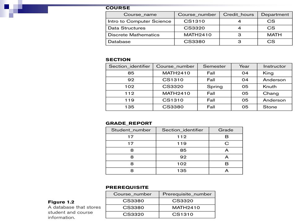
Example of a Database Mini-world for the example:
Part of a UNIVERSITY environment. Some mini-world entities: STUDENTs COURSEs SECTIONs (of COURSEs) (academic) DEPARTMENTs INSTRUCTORs Some mini-world relationships: SECTIONs are of specific COURSEs STUDENTs take SECTIONs COURSEs have prerequisite COURSEs INSTRUCTORs teach SECTIONs COURSEs are offered by DEPARTMENTs STUDENTs major in DEPARTMENTs
 (academic) DEPARTMENTs. INSTRUCTORs. Some mini-world relationships: SECTIONs are of specific COURSEs. STUDENTs take SECTIONs. COURSEs have prerequisite COURSEs. INSTRUCTORs teach SECTIONs. COURSEs are offered by DEPARTMENTs. STUDENTs major in DEPARTMENTs.")
10
Example of a Biological Database
DEFINITION Homo sapiens adrenergic, beta-1-, receptor ACCESSION NM_000684 SOURCE ORGANISM human REFERENCE 1 AUTHORS Frielle, Collins, Daniel, Caron, Lefkowitz, Kobilka TITLE Cloning of the cDNA for the human beta 1-adrenergic receptor REFERENCE 2 AUTHORS Frielle, Kobilka, Lefkowitz, Caron TITLE Human beta 1- and beta 2-adrenergic receptors: structurally and functionally related receptors derived from distinct genes 10

11
Main Characteristics of the Database Approach
Self-describing nature of a database system: A DBMS catalog stores the description of a particular database (e.g. data structures, types, and constraints) The description is called meta-data. This allows the DBMS software to work with different database applications. Insulation between programs and data: Called program-data independence. Allows changing data structures and storage organization without having to change the DBMS access programs. Data Abstraction: A data model is used to hide storage details and present the users with a conceptual view of the database. Programs refer to the data model constructs rather than data storage details Support of multiple views of the data: Each user may see a different view of the database, which describes only the data of interest to that user.
 The description is called meta-data. This allows the DBMS software to work with different database applications. Insulation between programs and data: Called program-data independence. Allows changing data structures and storage organization without having to change the DBMS access programs. Data Abstraction: A data model is used to hide storage details and present the users with a conceptual view of the database. Programs refer to the data model constructs rather than data storage details. Support of multiple views of the data: Each user may see a different view of the database, which describes only the data of interest to that user.")
12
Database Design Process
Two main activities: Database design Applications design Focus in this course on database design To design the conceptual schema for a database application Applications design focuses on the programs and interfaces that access the database Generally considered part of software engineering

13
Database Design Process

14
Course goals Understand the important concepts within databases and database terminology Design a database for a given application EER-modelling Design and use a relational database Concept of relations Use SQL Use MySQL Decipher a new relational database system Theoretical foundations behind relational databases Normalization Understand how the database is stored on the computer Basic technology, file structures, indexing Impact on database performance B-Trees, Hashing Understand how databases can support multiple users What problems occur Views Transactions Serialisation Understand how persistency can be guaranteed Recovery

15
Overview Real world Model Query Answer Database Physical database DBMS
Processing of queries and updates Access to stored data Now imagine that you and your group get a task. It is to design and implement a database application for company. What you need to do in the first? When we design a database, the first step is to collect and analyze user’s requirements. We interview the database users to understand and document their data requirments. Like what are the data must be included in the database, data types, relationships between data, and constraints must be hold for data, and functions they need in the database application. We describe the requirments using A high-level conceptual data model. Then in the next step of the database design, this high-level conceptual data model is transformed into implementation data model supported by DBMS, like relational model we introduced in the last lecture. The data model is in high level model. We do not need consider any implementation and storage details. With high level model, it is much easier to communicate with users, since usually they do not have technology backgroud. And also database designer can concentrate on the data requirments. 15 JMP

16
Entity-Relationship (ER) Model
High-level conceptual data model An overview of the database Easy to discuss with non-database experts Easy to translate to data model of DBMS ER diagram In this lecture we introduce a popular high-level conceptual data model, ER model, and their use in modelling The data model describes data requirements of a database on conceptual level, does not includes implementation details. It is easy to discuss with non-database experts using the model It is easy to translate it to data model of DBMS There are graphical notation associates with the ER model. A model can be displayed by a ER diagram. Model defines concepts that can be used to define a particular domain ER model: data structuring concepts and constraints. Conceptual design of database applications. Graphical model 16 JMP

17
Entity and entity type Entity – a ”thing” in the real world with an independent existence Attributes – properties that describes an entity Entity type – a collection of entities that have the same set of attributes Car RegNumber Model Year ER model describes data as entities, relationships and attributes. An entity represents a particular ”thing” in the real world. e.g. a particular car. An each entity has attributes. The attributes describe an entity. E.g. a car can be decribed by its model, year and registration number. Entity type – a collection of entities that have the same set of attributes. E.g. car. It is described by its names and attributes. In ER diagram, Entity types are shown in rectangular boxes. Attributes are shown in a ovals. An attribute is attached to its entity type by a straight line. e.g. the entity type car. A collection of cars have three attributes. Owner PersonalNumber Name 17 JMP

18
Attributes Simple vs composite Single-valued vs multivalued
Stored vs derived Owner PersonalNumber Name Age Address City Street PhoneNumber In ER model there are different types of attributes . Composite attributes can be divided into smaller subparts (attributes with independent meaning). E.g. address, divided into street and city. Simple attributes can not be divided into smaller subparts. A single-valued attribute has a single value for an entity. Multivalued – attributes can have a number of values for an entity. E.g. A person may have several phonenumbers. Derived – The value of a derived attribute can be derived from other attributes or related entities. Otherwise a attribute is a stored attribute. E.g. Age can be derived from the current date and the value of that person’s birthday. 18 JMP
. E.g. address, divided into street and city. Simple attributes can not be divided into smaller subparts. A single-valued attribute has a single value for an entity. Multivalued – attributes can have a number of values for an entity. E.g. A person may have several phonenumbers. Derived – The value of a derived attribute can be derived from other attributes or related entities. Otherwise a attribute is a stored attribute. E.g. Age can be derived from the current date and the value of that person’s birthday. 18. JMP.")
19
Constraints on attributes
Value sets (domains) of attributes Key attributes Owner PersonalNumber Name Age Address City Street PhoneNumber A database appllication has constraints on values of attributes They are specified by domains. A domain is specified by data type, such as real number, string and so on. For each entity type, there must be a set of attributes can be used to identify each entity uniquely. Such set of attributes is called a key of the entity type. E.g. the attribute ”personalNumber” can be a key of the entity type ”OWNER”. The value of a key is unique for each entity. So it can be used to uniquely identify entites. In ER diagram, each key attribute has its name underlined. Notice: The set of attributes in a key is minimal. It means that we can not remove any attribute from a key and still have the uniqueness condition hold. 19 JMP
 of attributes. Key attributes. Owner. PersonalNumber. Name. Age. Address. City. Street. PhoneNumber. A database appllication has constraints on values of attributes. They are specified by domains. A domain is specified by data type, such as real number, string and so on. For each entity type, there must be a set of attributes can be used to identify each entity uniquely. Such set of attributes is called a key of the entity type. E.g. the attribute personalNumber can be a key of the entity type OWNER . The value of a key is unique for each entity. So it can be used to uniquely identify entites. In ER diagram, each key attribute has its name underlined. Notice: The set of attributes in a key is minimal. It means that we can not remove any attribute from a key and still have the uniqueness condition hold. 19. JMP.")
20
Relationship type Relationship type – association among entity types
Car RegNumber Model Year N Owner PersonalNumber Name There are relationships between entity types. E.g. Owner owns car. Relationships are shown in diamonsds. Connected to entity types by straight lines. 1 owns 20 JMP

21
Constraints on relationship types
Cardinality ratio – maximum number of relationship instances that an entity can participate in possible cardinality ratio: 1:1, 1: N, N:1, N:M Owner Car owns 1 N M A database application has constraints on relationship types. Relationship types have certains constraints, (that limit the possible combinations of entities that may participate in relationships.) Cardinality ratio specifies maximum number of … The relationship type has candinality ratio 1:N, meaning that an owner can be related to many cars. So a owner can owns any number of car, but a car can only be related to one owner. Owner, car is of cardinality ratio N:M, meaning that each owner can owns any number of car, and a car can be related to any number of owner. In ER diagram, cardinality ratio is displayed by the number. 21 JMP
 Cardinality ratio specifies maximum number of … The relationship type has candinality ratio 1:N, meaning that an owner can be related to many cars. So a owner can owns any number of car, but a car can only be related to one owner. Owner, car is of cardinality ratio N:M, meaning that each owner can owns any number of car, and a car can be related to any number of owner. In ER diagram, cardinality ratio is displayed by the number. 21. JMP.")
22
Constraints on relationship types
Participant constraint Total participation – an entity must exist related to another entity Owner Car owns N M ”Every car must be owned by at least one owner.” PersonalNumber RegNumber Users may have a requirment that Every car must be owned by at least one owner. So each car must exist related to an owner in the database.. So all cars in the database participant in the relationship ”owns”. It is called total participant. It is showen by double straight line in ER diagram. Total participation is also called existence dependency. If a car does not have to have an owner, the participation of ”car” is partial participation. total participation: ett projekt måste kontrolleras av ett department. det får inte finnas projekt som inte kontrolleras av ett department svag identitet: En relative får inte finnas utan att det finns en identifierande anställd. svag relationship: visar det identifierande relationship för den svaga entiteten. Kan inte finnas N:M förhållande här eftersom varje svag entitet måste identifieras av precis en (stark) entitet. 22 JMP
 entitet. 22. JMP.")
23
Constraints on relationship types
Weak entity types– do not have key attibutes of their own. A weak entity can be identified uniquely by being related to another entity (together with its own attributes). name There are a kind of entities they do not have key attribute of their own. A weak entity must be identified by entity it is related to, probably together with its own attributes Football player example. name is almost a key for football players, but there might be two with the same name. number is certainly not a key, since players on two teams could have the same number. But number, together with the team name related to the player by Plays-on should be unique. &&&The reason we need weak entity here is that it is unlikely that there could be an agreement to assign unique player numbers across all football teams. In one team, the number of a player can be used to identify the player. The number is partial key for the weak entity. In ER diagram, a weak entity type is shown in a double rectangular box. The relationship type relates a weak entity type to its owner is called the identifying relationship of the weak entity type. It is shown as a double diamond. Partial key is underlined with a dotted line. ??? Candinality ratio of the identifying relationship type only can be 1:N or 1:1. ??? N:1, N:M, a weak entity is identified by two owner entities. They are not the same entity, two different entities. Existance vs identification; cardinality differences total participation: ett projekt måste kontrolleras av ett department. det får inte finnas projekt som inte kontrolleras av ett department svag identitet: En relative får inte finnas utan att det finns en identifierande anställd. svag relationship: visar det identifierande relationship för den svaga entiteten. Kan inte finnas N:M förhållande här eftersom varje svag entitet måste identifieras av precis en (stark) entitet. Name players N number 1 Plays_on team 23 JMP
. name. There are a kind of entities they do not have key attribute of their own. A weak entity must be identified by entity it is related to, probably together with its own attributes. Football player example. name is almost a key for football players, but there might be two with the same name. number is certainly not a key, since players on two teams could have the same number. But number, together with the team name related to the player by Plays-on should be unique. &&&The reason we need weak entity here is that it is unlikely that there could be an agreement to assign unique player numbers across all football teams. In one team, the number of a player can be used to identify the player. The number is partial key for the weak entity. In ER diagram, a weak entity type is shown in a double rectangular box. The relationship type relates a weak entity type to its owner is called the identifying relationship of the weak entity type. It is shown as a double diamond. Partial key is underlined with a dotted line. Candinality ratio of the identifying relationship type only can be 1:N or 1:1. N:1, N:M, a weak entity is identified by two owner entities. They are not the same entity, two different entities Existance vs identification; cardinality differences. total participation: ett projekt måste kontrolleras av ett department. det får inte finnas projekt som inte kontrolleras av ett department. svag identitet: En relative får inte finnas utan att det finns en identifierande anställd. svag relationship: visar det identifierande relationship för den svaga entiteten. Kan inte finnas N:M förhållande här eftersom varje svag entitet måste identifieras av precis en (stark) entitet. Name. players. N. number. 1. Plays_on. team. 23. JMP.")
24
Attributes of relationship types
”Store information on who owned which car and during which period of time” SellDate BuyDate Model Name RegNumber Year PersonalNumber Sometimes it is useful to attach an attribute to a relationship. ?For 1:N relationship type, a relationship attribute can be migrated only to the entity type on the N-side of the relationhship. Write on slide: “En ägare kan ha många (M) bilar, en bil kan ha många (N) ägare.” N M owns Owner Car 24 JMP
 bilar, en bil kan ha många (N) ägare. N. M. owns. Owner. Car. 24. JMP.")
25
N-ary relationships Example. A person works as an engineer at one company and as a gym instructor at another company. Company Employee JobType Company works as N M K Ternary N works at M Employee Example. with the first model, we only can model (e1, c1), (e1, c2) and (e1, j1), (e1, j2). We lose information. to model (e1, c1, j1) and (e2, c2, j2), Then we need N-ary relationships. More than two entity types can participant in a relationship type. Go back to the previous slide. The attributes of the relationship type entity type participant the relationship type. N works as M JobType 25 JMP
, (e1, c2) and (e1, j1), (e1, j2). We lose information. to model (e1, c1, j1) and (e2, c2, j2), Then we need N-ary relationships. More than two entity types can participant in a relationship type. Go back to the previous slide. The attributes of the relationship type entity type participant the relationship type. N. works as. M. JobType. 25. JMP.")
26
ER Notation R E1 E2 R E1 E2 JMP Symbol Meaning ENTITY TYPE
WEAK ENTITY TYPE RELATIONSHIP TYPE IDENTIFYING RELATIONSHIP TYPE ATTRIBUTE KEY ATTRIBUTE MULTIVALUED ATTRIBUTE COMPOSITE ATTRIBUTE DERIVED ATTRIBUTE TOTAL PARTICIPATION OF E2 IN R CARDINALITY RATIO 1:N FOR E1:E2 IN R Weak entity, relationship type connet to weak entity. Key attribute Total participant. Cardinality ratio. How to read the relationship. Proper naming is important. Not everything is displayed on an ER diagram. Domain of attribute, foriegn keys are not displayed in an ER diagram. R E1 E2 1 R N E1 E2 26 JMP

27
Example of a Biological Database
Reference protein-id accession definition source article-id title author PROTEIN ARTICLE m n 27

28
Enhanced ER (EER) Model
Why more? More complex data requirements Example. Only some employees can use a company car, only managers have to write a monthly report, but all employees have assigned personal number, salary account and a place in the office. Subclass/superclass, specialization/generalization, union/category attribute and relationship inheritance ER model is enough for representing many database schema. But some applications have more complex requirements. For example, we have such data requirement … ER model is not able to model these requirments. In this part we introduce the enhanced ER model. EER model includes all the modeling concepts of the ER model. In addition, it includes semantic data modeling concepts: Subclass/superclass, and the related concepts of Specialization/generalization Category/union type is used to represent a collection of objects that is the union of objects of different entity types. Associated with these concepts is the important mechanism of Attribute and relationship inheritance. 28 JMP

29
Subclass/Superclass specialization generalization process of defining
classes Surname FirstName PN Name Employee d o U U U U Commission Salesman Engineer Manager ProjectLeader 1 1 In the database application an entity type may have different subgroupings of its entities that are meaningful and need to be represented explicitly. E.g. EMPLOYEE entity type is grouped further into salesman, engineer, manager and project leader. Each of these subgrouping is called subclass of EMPLOYEE entity type. EMPLOYEE entity type is called the superclass for each of these subclass. Subclass inherits all the attributes of the entity of the superclasses, and also inherits all the relationships in which the superclass participates. (Every entity of these subclasses) All salesman, engineers, managers and project leaders are also employees. They have PN and name. Entities in each subclasses have their own specific properties. Subclass may have specific attributes. They only can be applied to entities of the subclass, e.g. Only salesmans have commision. Subclass may participant specific relationship type. E.g. Salesman participants in the use relationship type. An entity can not exist in the database only by being a member of subclass. It must be also be a member of the superclass. Subclasses are attached by lines to a circle. The circle represents the specialization, which is connected to the superclass. Subset symbol is from A < B. on each line indicates the direction of the super/subclass D, specifies that the subclasses must be disjoint. That means that an entity can be a member of at most one of the subclass. E.g. An employee can be either salesman or engineer. O specifies that the subclasses must be overlap. E.g. an employee can be both manger and project leader. Total specialization: an entity in the superclass must be a member of at least one sublcass. Total specialization is connected to the superclass by a double line. Assume that all employees must be either engineers or sales people, ______________________________________________________ Specialization is a process of defining subclasses of an entity type: Specialization is based on some distinguishing characteristics of superclass. e.g. The set of subclasses {salesman, engineer} is a specialization of EMPLOYEE based on the job type of each employee. We can have several specializations of the same entity type. E.g. Antoher specilization of EMPLOYEE is based on the type of leadership. Generalization is a reverse process of specialization– process of identifying common features among several entity types. Generalize them into a sigle superclass Confronted with a database containing data about engineers, sales people, managers and project leaders, there are common features of these four entity types. They all are an employee of the company, have attributes, PN, name, and so on. uses writes 1 N Car MonthlyReport RegNumber 29 ReportID JMP
 All salesman, engineers, managers and project leaders are also employees. They have PN and name. Entities in each subclasses have their own specific properties. Subclass may have specific attributes. They only can be applied to entities of the subclass, e.g. Only salesmans have commision. Subclass may participant specific relationship type. E.g. Salesman participants in the use relationship type. An entity can not exist in the database only by being a member of subclass. It must be also be a member of the superclass. Subclasses are attached by lines to a circle. The circle represents the specialization, which is connected to the superclass. Subset symbol is from A < B. on each line indicates the direction of the super/subclass. D, specifies that the subclasses must be disjoint. That means that an entity can be a member of at most one of the subclass. E.g. An employee can be either salesman or engineer. O specifies that the subclasses must be overlap. E.g. an employee can be both manger and project leader. Total specialization: an entity in the superclass must be a member of at least one sublcass. Total specialization is connected to the superclass by a double line. Assume that all employees must be either engineers or sales people, ______________________________________________________. Specialization is a process of defining subclasses of an entity type: Specialization is based on some distinguishing characteristics of superclass. e.g. The set of subclasses {salesman, engineer} is a specialization of EMPLOYEE based on the job type of each employee. We can have several specializations of the same entity type. E.g. Antoher specilization of EMPLOYEE is based on the type of leadership. Generalization is a reverse process of specialization– process of identifying common features among several entity types. Generalize them into a sigle superclass. Confronted with a database containing data about engineers, sales people, managers and project leaders, there are common features of these four entity types. They all are an employee of the company, have attributes, PN, name, and so on. uses. writes. 1. N. Car. MonthlyReport. RegNumber. 29. ReportID. JMP.")
30
Single vs. Multiple inheritance
Surname FirstName PN Name Employee d o U U U U Salesman Engineer Manager ProjectLeader Commission SoftwareProject PID Software ProjectLeader U manages N 1 These subclasses inherit attributes and relationships from one entity type. There a kind of subclass inherits attributes and relationships from more than one entity types. SoftwareProjectLeader inherits attributes and relationships from two superclasses ”Engineer” and ”ProjectLeader”. only project leaders that are engineers are allowed to lead software projects. Such a subclass is called shared subclass. So a shared subclass inherits attributes and relationships from multiple superclasses. 30 JMP

31
Union/category A subclass represents a collection of entities that is a subset of the UNION of the entities of multiple distinct superclasses CNumber Address PersonalNumber Person Company “An owner of a car is either a person or a company.” BirthDate u So owner is subclass of UNION of the two entity type, COMPANY and PERSON. An owner of a car is either a company or a person, not all persons own cars, but all company owns cars Such subclass is called category. The category is connected a circle with a U inside. Superclasses are connected to the circle. A total category holds the union of all entities in its superclasses. It is represented by a double line connecting the category and the circle. If all companies and banks and people own cars (owner is a total union) this can also be represented as a total specialisation. U 1 N Owner owns Car 31 JMP
 this can also be represented as a total specialisation. U. 1. N. Owner. owns. Car. 31. JMP.")
32
Example 3 A taxi company needs to model their activities
There are two types of employees in the company: drivers and operators. For drivers it is interesting to know the date of issue and type of the driving license, and the date of issue of the taxi driver’s certificate. For all employees it is interesting to know their personal number, address and the available phone numbers. The company owns a number of cars. For each car there is a need to know its type, year of manufacturing, number of places in the car and date of the last service. The company wants to have a record of car trips (körningar). A taxi may be picked on a street or ordered though an operator who assigns the order to a certain driver and a car. Departure and destination addresses together with times should also be recorded. No need to model the central station. Core information – car runs together with all relevant information. 32 JMP
. A taxi may be picked on a street or ordered though an operator who assigns the order to a certain driver and a car. Departure and destination addresses together with times should also be recorded. No need to model the central station. Core information – car runs together with all relevant information. 32. JMP.")
33
Employee U U Driver Operator 1 1 N N Trip N 1 Car drives assign
Street PN Address Phone PostNumber Town Employee o TaxiCertifDate U U DrivingLicenseDate DrivingLicenseDate Driver Operator 1 1 DrivingLicenseType DrivingLicenseType drives assign N Type DepTime N Trip YearOfManuf DeparturePlace RegNumber Tveksamt för att modellen inte visar att en förare kan ha många körkorts(typer). Here we have an assumption that each driver only can have one driving license. With this model we can not model driver with more than one drive licenses. Typical exam errors: - Forget cardinalities, primary key attributes - Wrong subclass notation (where goes the primary key?) - No use of total participation or weak entities ServiceDate Destination DestTime N Places made_by 1 Car ID 33 JMP
. Here we have an assumption that each driver only can have one driving license. With this model we can not model driver with more than one drive licenses. Typical exam errors: - Forget cardinalities, primary key attributes. - Wrong subclass notation (where goes the primary key ) - No use of total participation or weak entities. ServiceDate. Destination. DestTime. N. Places. made_by. 1. Car. ID. 33. JMP.")
34
Driver N 1 Körkort Driver N M Driver belongsTo belongsTo
TaxiCertifDate A driver may have many driving licenses (types) DrivingLicenseDate Driver DrivingLicenseType Date Type Id TaxiCertifDate N belongsTo 1 Körkort belongsTo DrivingLicense Driver TaxiCertifDate Type 2nd case. DL types are tight to the table definition. May not be convenient if the types have to be extended by the user. 3rd case. Allows the user to extend types. DrivingLicense N belongsTo M Driver Date 34 JMP
 DrivingLicenseDate. Driver. DrivingLicenseType. Date. Type. Id. TaxiCertifDate. N. belongsTo. 1. Körkort. belongsTo. DrivingLicense. Driver. TaxiCertifDate. Type. 2nd case. DL types are tight to the table definition. May not be convenient if the types have to be extended by the user. 3rd case. Allows the user to extend types. DrivingLicense. N. belongsTo. M. Driver. Date. 34. JMP.")
35
Summary Entity-Relationship (ER) diagram – a graphical way to model the world Main concepts - entity, relationship and attribute Different types of constraints Enhanced ER model Today we introduce the high level conceptual data model to model data requirments of users. 35 JMP

Similar presentations


 Model.>")


 modelling Jose M. Peña jose.m.pena@liu.se.>")


 Model Dr. Bernard Chen Ph.D. University of Central Arkansas.>")
