Download presentation
Presentation is loading. Please wait.

1
Unit-3 SUBSTATIONS

2
TOPICS Classification of substations : Indoor & Outdoor substations
Substations layout showing the location of all the substation equipment. Bus bar arrangements in the Sub-Stations: Simple arrangements like 1. Single Bus Bar 2. Sectionalized Single Bus Bar 3. Main and Transfer Bus Bar System with relevant diagrams.

3
Introduction The present-day electrical power system is a.c.
Electric power is generated, transmitted and distributed in the form of alternating current. The electric power stations are located at far away from the consumers or load centers. At many places in the power system, it is desirable and necessary to change some characteristic of electric supply.

4
Sub-Station An assembly of apparatus installed to perform voltage transformation, switching, power factor correction, power and frequency –converting operation. The sub-stations are used to change some characteristic of electric supply in the power system. Voltage A.C. to D.C. Frequency Power Factor

5
Factors governing the selection of site
Sub-stations are important part of power system. The continuity of supply. Near the load centre (at the centre of gravity of load) of its service areas. Proper access for incoming sub transmission lines and outgoing primary feeders. Easy access for repairs and maintenance, abnormal occurrences such as possibility of explosion or fire etc. Enough space for future expansion. Minimum capital cost.
 of its service areas. Proper access for incoming sub transmission lines and outgoing primary feeders. Easy access for repairs and maintenance, abnormal occurrences such as. possibility of explosion or fire etc. Enough space for future expansion. Minimum capital cost.")
6
Classification of Sub-Stations
According to Service requirement Design (constructional features).
.")
7
According To Service Requirement
Transformer sub-stations: Transform power from one voltage level to another . Transformer will be the main component Switching sub-stations: Switching operations of power lines Synchronous (Power factor correction) Substations: Improves the power factor of the system. Located at the receiving end of transmission lines. Synchronous condensers for p.f improvement.
 Substations: Improves the power factor of the system. Located at the receiving end of transmission lines. Synchronous condensers for p.f improvement.")
8
According To Service Requirement
Frequency changer sub-stations: Convert normal frequency to other useful. Converting sub-stations: Convert a.c. power into d.c. power Electric traction, electroplating, electric welding, battery charging, etc. Industrial sub-stations: Industrial consumers (huge amounts of power) Individual sub-stations
 Individual sub-stations.")
9
According to Design (Constructional features)
A sub-station has many components (e.g. insulators, bus bars,transformers, circuit breakers, switches, fuses, instruments etc.) which must be properly protected for continuous and reliable service. Indoor sub-stations: Equipment are installed indoor (within a building) Generally used for voltages upto 11 kV only Atmosphere is contaminated with impurities such as metal corroding gases and fumes , conductive dust etc.
 which must be properly protected for continuous and reliable service. Indoor sub-stations: Equipment are installed indoor (within a building) Generally used for voltages upto 11 kV only. Atmosphere is contaminated with impurities such as metal corroding gases and fumes , conductive dust etc.")
10
According to Design (Constructional features)
Outdoor sub-stations: For voltages beyond 11 kV, equipment is invariably installed outdoor More clearances between conductors and the space required for switches, circuit breakers and other equipment Not economical to install the equipment indoor. Underground sub-stations: In thickly populated areas The space available for equipment and building is limited and the cost of land is high. Pole-mounted sub-stations: These are used for distribution purposes only Equipment installed overhead on H-pole or 4-pole structure It is the cheapest form of sub-station

11
Comparison between Outdoor and Indoor Sub-Stations
S.No Particular Outdoor Sub-station Indoor Sub-station 1 Space required More Less 2 Time required for erection 3 Future extension Easy Difficult 4 Fault location Easier because the equipment is in full view Difficult because the equipment is enclosed 5 Capital cost Low High 6 Operation Easier 7 Possibility of fault escalation Less because greater clearances can be provided

12
Transformer Sub-Stations
The majority of the sub-stations Transformer is the main component employed to change the voltage level. Depending upon the purpose served classified into : (i) Step-up sub-station (ii) Primary grid sub-station (iii) Secondary sub-station (iv) Distribution sub-station
 Step-up sub-station. (ii) Primary grid sub-station. (iii) Secondary sub-station. (iv) Distribution sub-station.")
13
The block diagram of supply system indicating the position of sub-stations

14
Primary grid sub-station:
Step-up sub-station: The generation voltage (11 kV) is stepped up to high voltage 220 kV Electric power transmitted by 3-ph, 3-wire overhead system to the outskirts of the city These are generally located in the power houses Outdoor type Primary grid sub-station: From the step-up sub-station, electric power is received by the primary grid sub-station Reduces the voltage level to 66 kV for secondary transmission Electric power is transmitted at 66 kV by 3-phase, 3-wire system to various secondary sub-stations located at the strategic points in the city
 is stepped up to high voltage 220 kV. Electric power transmitted by 3-ph, 3-wire overhead system to the outskirts of the city. These are generally located in the power houses. Outdoor type. Primary grid sub-station: From the step-up sub-station, electric power is received by the primary grid sub-station. Reduces the voltage level to 66 kV for secondary transmission. Electric power is transmitted at 66 kV by 3-phase, 3-wire system to various secondary sub-stations located at the strategic points in the city.")
15
Secondary sub-station:
From the primary grid sub-station, electric power is received by the secondary grid sub-station The voltage is further stepped down to 11 kV The 11 kV lines run along the important road sides of the city. Big consumers (having demand more than 50 kW) are generally supplied power at 11 kV Outdoor type Distribution sub-station: The electric power from 11 kV lines is delivered to distribution sub-stations These sub-stations are located near the consumer’s localities Step down the voltage to 400 V, 3-phase, 4-wire for supplying to the consumers.
 are generally supplied power at 11 kV. Outdoor type. Distribution sub-station: The electric power from 11 kV lines is delivered to distribution sub-stations. These sub-stations are located near the consumer’s localities. Step down the voltage to 400 V, 3-phase, 4-wire for supplying to the consumers.")
16
Equipment in a Transformer Sub-Station
1.Bus-bars: When a number of lines operating at the same voltage have to be directly connected electrically, bus-bars are used as the common electrical component Bus-bars are copper or aluminum bars (rectangular x-section) Operate at constant voltage The incoming and outgoing lines in a sub-station are connected to the bus-bars The most commonly used bus-bar arrangements in sub-stations are : (i) Single bus-bar arrangement (ii) Single bus-bar system with sectionalisation (iii) Main and transfer bus-bar arrangement 2. Insulators: They support the conductors (or bus-bars) and confine the current to the conductors The most commonly used material is porcelain There are several types of insulators pin type suspension type post insulator etc
 Operate at constant voltage. The incoming and outgoing lines in a sub-station are connected to the bus-bars. The most commonly used bus-bar arrangements in sub-stations are : (i) Single bus-bar arrangement. (ii) Single bus-bar system with sectionalisation. (iii) Main and transfer bus-bar arrangement. 2. Insulators: They support the conductors (or bus-bars) and confine the current to the conductors. The most commonly used material is porcelain. There are several types of insulators. pin type. suspension type. post insulator etc.")
19
Equipment in a Transformer Sub-Station
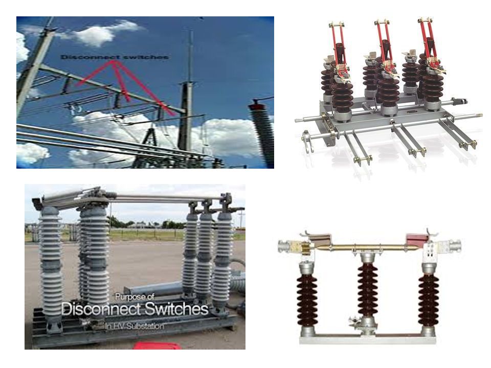
3. Isolating switches : To disconnect a part of the system for general maintenance and repairs An isolator is essentially a knife switch and is designed to open a circuit under no load Operated only when the lines carry no current 4.Circuit breaker: An equipment which can open or close a circuit under normal as well as fault conditions It is so designed that it can be operated manually (or by remote control) under normal conditions and automatically under fault conditions For the fault conditions operation, a relay circuit is used with a circuit breaker
 under normal conditions and automatically under fault conditions. For the fault conditions operation, a relay circuit is used with a circuit breaker.")
22
Equipment in a Transformer Sub-Station
5. Power Transformers: To step-up or step-down the voltage Except at the power station, all the subsequent sub-stations use step-down transformers 6. Instrument transformers: The lines in sub-stations operate at high voltages and carry current of thousands of amperes The measuring instruments and protective devices are designed for low voltages (generally 110 V) and currents (about 5 A) They will not work satisfactorily if mounted directly This difficulty is overcome by installing instrument transformers Transfer voltages or currents in the power lines to values which are convenient for measuring instruments and relays Two types (i) Current transformer (C.T.) (ii) Potential transformer (P.T.)
 and currents (about 5 A) They will not work satisfactorily if mounted directly. This difficulty is overcome by installing instrument transformers. Transfer voltages or currents in the power lines to values which are convenient for measuring instruments and relays. Two types. (i) Current transformer (C.T.) (ii) Potential transformer (P.T.)")
24
Equipment in a Transformer Sub-Station
(i) Current transformer (C.T.): It is a transformer which steps down the current to a known ratio The primary consists of one or more turns of thick wire connected in series with the line The secondary consists of a large number of turns of fine wire and provides for the measuring instruments and relays a current which is a constant fraction of the current in the line Suppose a current transformer rated at 100/5 A is connected in the line to measure current. If the current in the line is 100 A, then current in the secondary will be 5A. Similarly, if current in the line is 50A, then secondary of C.T. will have a current of 2·5 A. Thus the C.T. under consideration will step down the line current by a factor of 20.
 Current transformer (C.T.): It is a transformer which steps down the current to a known ratio. The primary consists of one or more turns of thick wire connected in series with the line. The secondary consists of a large number of turns of fine wire and provides for the measuring instruments and relays a current which is a constant fraction of the current in the line. Suppose a current transformer rated at 100/5 A is connected in the line to measure current. If the current in the line is 100 A, then current in the secondary will be 5A. Similarly, if current in the line is 50A, then secondary of C.T. will have a current of 2·5 A. Thus the C.T. under consideration will step down the line current by a factor of 20.")
26
Equipment in a Transformer Sub-Station
(ii) Potential transformer: It is a transformer which steps down the voltage to a known ratio The primary consists of a large number of turns of fine wire connected across the line. The secondary winding consists of a few turns and provides for measuring instruments and relays a voltage which is a known fraction of the line voltage. Suppose a potential transformer rated at 66kV/110V is connected to a power line. If line voltage is 66kV, then voltage across the secondary will be 110 V.
 Potential transformer: It is a transformer which steps down the voltage to a known ratio. The primary consists of a large number of turns of fine wire connected across the line. The secondary winding consists of a few turns and provides for measuring instruments and relays a voltage which is a known fraction of the line voltage. Suppose a potential transformer rated at 66kV/110V is connected to a power line. If line voltage is 66kV, then voltage across the secondary will be 110 V.")
28
Equipment in a Transformer Sub-Station
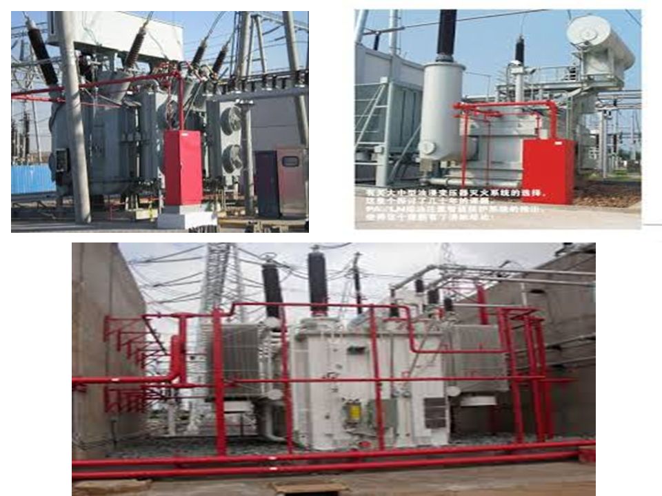
7. Protective relays: These are installed for ptotection of equipment against faults or over loads 8. Metering and Indicating Instruments: These are installed to watch and maintain the circuit quantities. e.g. ammeters, voltmeters, energy meters etc. The instrument transformers used with them for satisfactory operation. 9.Miscellaneous equipment. (i) Lightening arresters. (ii) Fire fighting equipment (iii) sub-station auxiliary supplies
 Lightening arresters. (ii) Fire fighting equipment. (iii) sub-station auxiliary supplies.")
32
Symbols for Equipment in Sub-Stations

33
Symbols for Equipment in Sub-Stations

34
Symbols for Equipment in Sub-Stations

35
Bus-Bar Arrangements in Sub-Stations
Important components in a sub-station. There are several bus-bar arrangements The choice depends upon various factors such as system voltage, position of sub-station, degree of reliability, cost etc. (i) Single bus-bar system (ii) Single bus-bar system with sectionalisation (iii) Main and Transfer bus-bar system
 Single bus-bar system. (ii) Single bus-bar system with sectionalisation. (iii) Main and Transfer bus-bar system.")
36
(i) Single bus-bar system
It consists of a single bus-bar All the incoming and outgoing lines are connected to the same bus bar. Low initial cost Less maintenance and simple operation The equipment connections are very simple and hence the system is very convenient to operate If the fault occurs on any section of the bus, the entire bus bar is to be de-energized for carrying out repair work. This results in a complete interruption of the supply. Not used for voltages above 33kV. The indoor 11kV sub-stations are single bus-bar arrangement.

37
(i) Single bus-bar system
The two 11kV incoming lines connected to the bus-bar through circuit breakers and isolators. The two 400V outgoing lines are connected to the bus bars through isolator, circuit breaker and step down transformer (11kV/400 V) from the bus bars
 from the bus bars.")
38
(i) Single bus-bar system
Advantages: Each of the outgoing circuit requires a single circuit breaker. It is the cheapest The relaying system is simple The maintenance cost is low Disadvantages: Maintenance without interruption of supply is not possible. Expansion of substation without shutdown is not possible.

39
(ii) Single Bus-Bar System with Sectionalisation
The single bus-bar is divided into 2 or 3 sections Load is equally distributed on all the sections. Any two sections of the bus bar are connected by a circuit breaker and isolators. If a fault occurs on any section of the bus, that section can be isolated without affecting the supply from other sections. The repairs and maintenance of any section of the bus bar can be carried out by de-energizing that section only, eliminating the possibility of complete shutdown. This arrangement is used for voltages up to 33 kV.

40
(ii) Single bus-bar system with sectionalisation
Two 33 kV incoming lines connected to sections I and II through circuit breaker and isolators. Each 11 kV outgoing line is connected to one section through transformer (33/11 kV) and circuit breaker. Each bus-section behaves as a separate bus-bar.
 and circuit breaker. Each bus-section behaves as a separate bus-bar.")
41
(ii) Single bus-bar system with sectionalisation
Advantages: The operation is simple as in case of the single bus bar For maintenance or repair of the bus bar, only one half of the bus bar is required to be de-energized. The relaying system is simple The maintenance cost is low Disadvantages: In case of a fault on the bus bar, one half of the section will be switched-off. Maintenance without interruption of supply is not possible.

42
(iii) Main and Transfer bus-bar system:
It consists of two bus-bars, a “main” bus-bar and a “Transfer or spare” bus-bar Each bus-bar has the capacity to take up the entire sub-station load. The incoming and outgoing lines can be connected to either bus-bar with the help of a bus-bar coupler bus-bar coupler consists of a circuit breaker and isolators. Generally, the incoming and outgoing lines remain connected to the main bus-bar. In case of repair of main bus-bar or fault occurring on it, the continuity of supply to the circuit can be maintained by transferring it to the Transfer bus-bar. Frequently used for voltages exceeding 33kV.

43
(iii) Main and Transfer bus-bar system:
The arrangement of main and transfer bus-bar system in a typical sub-station. The two 66kV incoming lines can be connected to either bus-bar by a bus-bar coupler. The two 11 kV outgoing lines are connected to the bus-bars through transformers (66/11 kV) and circuit breakers
 and circuit breakers.")
44
(iii) Main and Transfer bus-bar system:
Advantages: It ensures supply in case of bus fault. In case of any fault on the bus bar, the circuit can be transferred to the transfer bus. It is easy to connect the circuit from any bus. The maintenance cost decreases. Disadvantages: Requires one extra circuit breaker. Switching is somewhat complicated while maintaining a breaker. Failure of bus bar or any circuit breaker results in shutdown of the entire substation.

Similar presentations


 = Volts.>")


