Download presentation
Presentation is loading. Please wait.

1
Naba K Mondal TIFR, Mumbai ICAL ( conceptual) INO Peak at Bodi West Hills Prototype ICAL at VECC 2mX2m RPC Test Stand at TIFR ASIC for RPC designed at BARC RPC Test stand at TIFR
 INO Peak at Bodi West Hills Prototype ICAL at VECC 2mX2m RPC Test Stand at TIFR ASIC for RPC designed at BARC RPC Test stand at TIFR")
2
India had a long tradition of carrying out experiments deep underground. KGF laboratory was the deepest underground laboratory during the period 1951-1992. First atmospheric neutrino was detected at KGF at a depth of 2.3km way back in 1965 by the TIFR- Osaka-Durham group. During late 70s & early 80s dedicated detectors were setup at KGF by TIFR-Osaka collaboration to look for proton decay. KGF mines closed its operation in 1992.

4
Atmospheric neutrino detector at Kolar Gold Field –1965 at Kolar Gold Field –1965 PRL 15, (1965), 429, dated 30th Aug. 1965 Physics Letters 18, (1965) 196, dated 15th Aug 1965
 196, dated 15th Aug")
6
Underground laboratory with ~1 km all-round rock cover accessed through a 2 km long tunnel. A large and several smaller caverns to facilitate many experimental programmes. Frontline neutrino issues e.g., mass parameters and other properties, will be explored in a manner complementary to ongoing efforts worldwide. The ICAL detector, with its charge identification ability, will be able to address questions about the neutrino mass ordering. Distance from CERN (Switzerland) and JPARC (Japan) ~ 7000 km, close to “magic baseline” for experiments with neutrino beams in a few decade from now Will support several other experiments when operational. Neutrino-less Double Beta Decay and Dark Matter Search experiments foreseen in the immediate future. INO facility will be available for international community for setting up experiments.
 and JPARC (Japan) ~ 7000 km, close to magic baseline for experiments with neutrino beams in a few decade from now Will support several other experiments when operational. Neutrino-less Double Beta Decay and Dark Matter Search experiments foreseen in the immediate future. INO facility will be available for international community for setting up experiments..")
7
Ahmedabad: Physical Research Laboratory (PRL); Aligarh: Aligarh Muslim University (AMU); Allahabad: Harish Chandra Research Institute (HRI); Calicut : University of Calicut; Chandigarh: Panjab University (PU); Chennai : Indian Institute of Technology, Madras (IITM); Chennai : The Institute of Mathematical Sciences (IMSc) ; Delhi : Delhi University (DU); Guwahati : Indian Institute of Technology (IITG); Hawaii (USA) : University of Hawaii (UHW); Indore: Indian Institute of Technology (IITInd); Jammu : University of Jammu (JU) ; Kalpakkam : Indira Gandhi Center for Atomic Research (IGCAR); Kolkata : Ramakrishna Mission Vivekananda University (RMVU); Kolkata : Saha Institute of Nuclear Physics (SINP); Kolkata : University of Calcutta (CU) ; Kolkata : Variable Energy Cyclotron Centre (VECC) ; Lucknow : Lucknow University (LU); Madurai : American College; Mumbai : Bhabha Atomic Research Centre (BARC) ; Mumbai : Indian Institute of Technology, Bombay (IITB) ; Mumbai : Tata Institute of Fundamental Research (TIFR); Mysore : University of Mysore (MU) ; Sambalpur : Sambalpur University; Srinagar : University of Kashmir; Varanasi : Banaras Hindu University (BHU)
; Aligarh: Aligarh Muslim University (AMU); Allahabad: Harish Chandra Research Institute (HRI); Calicut : University of Calicut; Chandigarh: Panjab University (PU); Chennai : Indian Institute of Technology, Madras (IITM); Chennai : The Institute of Mathematical Sciences (IMSc) ; Delhi : Delhi University (DU); Guwahati : Indian Institute of Technology (IITG); Hawaii (USA) : University of Hawaii (UHW); Indore: Indian Institute of Technology (IITInd); Jammu : University of Jammu (JU) ; Kalpakkam : Indira Gandhi Center for Atomic Research (IGCAR); Kolkata : Ramakrishna Mission Vivekananda University (RMVU); Kolkata : Saha Institute of Nuclear Physics (SINP); Kolkata : University of Calcutta (CU) ; Kolkata : Variable Energy Cyclotron Centre (VECC) ; Lucknow : Lucknow University (LU); Madurai : American College; Mumbai : Bhabha Atomic Research Centre (BARC) ; Mumbai : Indian Institute of Technology, Bombay (IITB) ; Mumbai : Tata Institute of Fundamental Research (TIFR); Mysore : University of Mysore (MU) ; Sambalpur : Sambalpur University; Srinagar : University of Kashmir; Varanasi : Banaras Hindu University (BHU)")
8
Construction of an underground laboratory and surface facilities near Pottipuram village in Theni district of Tamil Nadu. Construction of the 50 kton magnetised Iron calorimeter (ICAL) detector to study properties of neutrinos. Construction of the INO centre- The National Centre for High Energy Physics (NCHEP) at Madurai. Human Resource Development ( INO Graduate Training Program) Detector R & D
 detector to study properties of neutrinos. Construction of the INO centre- The National Centre for High Energy Physics (NCHEP) at Madurai. Human Resource Development ( INO Graduate Training Program) Detector R & D.")
10
10

11
Physics goal: A large mass detector with charge identification capability A large mass detector with charge identification capability Improved measurement of oscillation parameters. Search for potential matter effect in neutrino oscillation. Determining the sign of m 2 23 using matter effect Measuring deviation from maximal mixing for 23 Probing CP and CPT violation. Constraining long range leptonic forces. Ultra high energy neutrinos and muons.

12
The disappearance probability can be measured with a single detector and two equal sources: = P( ; L/E) N up (L/E) N down (L ’ /E) = 1 - sin2 (2 ) sin2 (1.27 m2 L/E)
 N up (L/E) N down (L ’ /E) = 1 - sin2 (2 ) sin2 (1.27 m2 L/E)")
13
13 R. Gandhi et al PRL 94, 051801, 2005

14
Blennow & Schwetz 2012

16
7000 KM

18
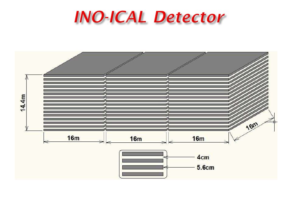
No of modules 3 Module dimension 16 m X 16 m X 12 m Detector dimension 48 m X 16 m X 12 m No of layers 140 Iron plate thickness 6 cm Gap for RPC trays 2.5 cm Magnetic field 1.5 Tesla RPC unit dimension 2 m X 2 m Readout strip width 2 cm No. of RPCs/Road/Layer 8 No. of Roads/Layer/Module 8 No. of RPC units/Layer 192 Total no of RPC units 27000 No of Electronic channels 3.6 X 10 6 18

19
Pickup strips Two 2 mm thick float Glass Separated by 2 mm spacer 2 mm thick spacer Glass plates Resistive coating on the outer surfaces of glass

20
Construction of the ICAL detector 20

21
No of modules 3 Module dimension 16 m X 16 m X 12 m Detector dimension 48 m X 16 m X 12 m No of layers 140 Iron plate thickness 6 cm Gap for RPC trays 2.5 cm Magnetic field 1.5 Tesla RPC unit dimension 2 m X 2 m Readout strip width 2 cm No. of RPCs/Road/Layer 8 No. of Roads/Layer/Module 8 No. of RPC units/Layer 192 Total no of RPC units 27000 No of Electronic channels 3.6 X 10 6 21

22
Fabrication of 1m x 1m RPCs 22

23
23

25
Prototype Glass RPC Stack at TIFR tracking Muons 25

26
26

27
VME BASED DAQ SETUP X strip data Y strip data Timing info Digital Front End Analog Front End Trigger Module Event Trigger Event/ Monitor Data VME CRATE Scaler TDC Readout Module Linux based DAQ software (C++, Qt, ROOT) Interrupt Based Multi-Threaded Graphical User Interface Online 2D/3D Event Display RPC Strip Monitoring Online Error Reporting RPC Stack 27
 Interrupt Based Multi-Threaded Graphical User Interface Online 2D/3D Event Display RPC Strip Monitoring Online Error Reporting RPC Stack 27")
28
Some interesting cosmic ray tracks 28

29
Strip Multiplicity due to crossing muons Track residue in mm Strip noise rate vs time Image of a RPC using muons

30
Muon flux measurement at sea level & at lower latitude (18 0 N) General muon flux distribution n=2.15 ± 0.01 I 0 = (6.217 ± 0.005)×10 -3 cm -2 s -1 str -1
 General muon flux distribution n=2.15 ± 0.01 I 0 = (6.217 ± 0.005)×10 -3 cm -2 s -1 str -1")
31
For a constant time resolution of 1.5 ns for all layers, for time fit slope for a vertical track is ~0.3. Data gives 1 = 0.326 for ndf>2. This says misidentification in directionality is ~0.3% within 5 limit Peak: ~1.0 MisIdentified

32
32 Prototype Magnet & RPC setup at VECC, Kolkata

33
33

34
34 Gas flow for five RPCs (2m × 2m) in new lab is reduced to 0.29 SCCM (1 volume change per 19 days). Long-term performance studies on these RPCs is in progress. At present, gas flow for the RPC (1mx1m) stack in C217 lab is 2.25 SCCM (1.6 volume change per day ) i.e. 1 volume change per 0.62 days.
 stack in C217 lab is 2.25 SCCM (1.6 volume change per day ) i.e. 1 volume change per 0.62 days..")
35
35

36
36

37
37

38
38

39
39

40
Simulation Framework NUANCE GEANT4 Neutrino Event Generation ν a + X -> A + B +... Generates particles that result from a random interaction of a neutrino with matter using theoretical models. Output: i) Reaction Channel ii) Vertex Information Iii) Energy & Momentum of all Particles Event Simulation A + B +... through RPCs + Mag.Field Simulate propagation of particles through the detector (RPCs + Magnetic Field) Output: i) x,y,z,t of the particles at their interaction point in detector ii) Energy deposited iii) Momentum information Event Digitisation (x,y,z,t) of A + B +... + noise + detector efficiency Add detector efficiency and noise to the hits Output: i) Digitised output of the previous stage (simulation) Event Reconstruction (E,p) of ν + X = (E,p) of A + B +... Fit the tracks of A + B +... to get their energy and momentum. Output: i) Energy & Momentum of the initial neutrino 40
 Reaction Channel ii) Vertex Information Iii) Energy & Momentum of all Particles Event Simulation A + B +... through RPCs + Mag.Field Simulate propagation of particles through the detector (RPCs + Magnetic Field) Output: i) x,y,z,t of the particles at their interaction point in detector ii) Energy deposited iii) Momentum information Event Digitisation (x,y,z,t) of A + B noise + detector efficiency Add detector efficiency and noise to the hits Output: i) Digitised output of the previous stage (simulation) Event Reconstruction (E,p) of ν + X = (E,p) of A + B +... Fit the tracks of A + B +... to get their energy and momentum. Output: i) Energy & Momentum of the initial neutrino 40.")
41
Trigger criteria based on event topology alone. Distributed and hierarchical architecture. Detector module segmented to generate local trigger. Combination of local triggers produces global trigger. Global trigger latches event data.

42
µ Events Muon events and neutrino events are generated with event vertices randomly distributed over the fiducial volume of the detector. Events are simulated using the INO-ICAL simulation code and the Digitization output is used to determine the trigger efficiency. Analysis algorithm complies with the architecture of the trigger system. Trigger efficiency is determined for Segment size 4m x 4m x 4m. Trigger criteria 1x5/8 2x4/8 3x3/8 4x2/8 CC ν Events

43
Surface plot of |B| Region where |B| ≥ 1 T is ~ 87% |B| ≥ 1 T 43 Magnet simulation

44
Human Resource development & Training INO Training School: We have already started INO graduate training program from August 2008. Affiliated to HBNI. At present INO students are being trained for one year at TIFR, Mumbai in both experimental techniques and theory. Being attached to Ph.D. guides at various collaborating institutions for a Ph. D. degree after completion of coursework 2008 2009 44

45
RPC development - Full size RPCs (2m X 2m) are now being fabricated not only in our lab but also by the Industry. Electronics- First batch of ASIC front end designed by the INO electronics team and fabricated by Euro Practice IC Services being tested in the lab using RPC pulses. Magnet- Prototype magnet at VECC/SINP, Kolkata is running. 2 nd Engineering module will be fabricated during next 2 years. Human Resource- Graduate Training Programme for the last three years within HBNI INO Site- Environment & Forest clearances obtained. 26 Hectares of land at Pottipuram provided by TN Govt. free of cost. 12 Hectares at Madurai will be provided by TN Govt. against payment.

46
PERT CHART 46

47
Thank you Thank You 47

Similar presentations


 STATUS REPORT Naba K Mondal Tata Institute of Fundamental Research Mumbai, India NUFACT Scoping Study Meeting at.>")

 Naba K Mondal Tata Institute of Fundamental Research Tata Institute of Fundamental Research Mumbai, India.>")


 INO Peak at Bodi West Hills Prototype ICAL at VECC 2mX2m RPC Test Stand at TIFR ASIC for RPC designed at.>")

