Download presentation
Presentation is loading. Please wait.

1
Active Ankle-Foot Orthotic Air Muscle Tethered Team P13001 Nathan Couper, ME Bob Day, ME Patrick Renahan, IE Patrick Streeter, ME This material is based upon work supported by the National Science Foundation under Award No. BES-0527358. Any opinions, findings, and conclusions or recommendations expressed in this material are those of the author and do not necessarily reflect the views of the National Science Foundation.

2
Agenda Assumptions Customer Needs Engineering Specifications Test Plan Mechanical Analysis – Proximal Attachment Static Analysis Fatigue Analysis – Distal Attachment Static Analysis Fatigue Analysis Air Muscle Testing – Transient Flow – Muscle Contractions Risk Assessment Proposed Schedule Questions and Criticism

3
Assumptions and Project Scope Patient maintains zero muscle control over dorsi-flexion, plantar-flexion, and toe extension This product is designed to be used on a treadmill in a clinical setting; but can be incorporated into an aquatic setting – Tethered System The elastomer can be adjusted on a patient basis so that when the patient’s full weight is applied on the AFO, the foot rests at angle slightly above 90 degrees with respect to the patient’s lower limb Designed patient has the ability to use a dorsi-flex assist AFO without receiving tone-lock spasms For calculations: – Anthropometric Data is from the ANSUR (military) Database Based on the 50th percentile man – 2D system – no resistive forces/friction associated with the joints – a normal gait cycle time of 1.2 to 1.5 steps per second is assumed – Isotropic, Elastic Materials
 Database Based on the 50th percentile man – 2D system – no resistive forces/friction associated with the joints – a normal gait cycle time of 1.2 to 1.5 steps per second is assumed – Isotropic, Elastic Materials")
4
Customer Needs Objective Number Customer Objective DescriptionComment/Status S1 follow safety guidelines and standards S3energy stored safely Air source designed for specified pressure S4no sharp protrusions Attachments designed to be flush inside AFO S5allergy conscious No new materials to be in contact with user FT1 support regular gait cycle System designed for responsiveness necessary for normal gait FT2 hold foot up when stepping forward Dorsi-assist AFO design has been proven successful

5
FT2 range of motion to allow full dorsiflexion and plantar flexion Tamarac joint allows flexion of joint. Hard stops of AFO prevent over flexion FT4resist foot slap Dorsi-assist AFO design has been proven successful FT5 operate smoothly/simulate normal muscle behavior Regulation of air muscles will allow for adjustment on patient by patient basis FT6 allow for extended use without straining leg from weight CF2non-invasive Designed to not interfere with normal fit of AFO CF3secure foot in orthotic Existing orthotic attachment is unchanged CF4non-abrasive No new materials to be in contact with user CF6allow normal cooling of leg This is a challenge with existing orthotics: vent holes will be drilled into orthotic CF7allow bending of kneeOrthotic will stop below the knee CF8allow toes to flex up Toe flexion will not be hampered by air muscle device

6
ST1b allow natural movement down stairs and ramps Air muscle system will provide proper plantar flexion during gait cycle ST2adapt to different terrains Terrain sensing system will be compatible with air muscle control ST3 fast system response between sensing and doing Low computative demands on system. Concern is with actuation speed. Intial testing suggests system has responsiveness required ST4 correctly interprets sensor information Sensor integration with team 13002 is pending ST5support foot drop over obstacles Dorsi-assist AFO design has been proven successful

7
Engineering Specs Engineering Specification Number Engineering Specification Description Units Nominal Value* Ideal Value ** Method of Validation Comments s1Torque on FootN-m ≥ ±1.5 F muscle = 53.10 N Test Force represents requirement for 50th percentile male s2Air muscle fill timeMs<150<200TestBased on descending stairs gait analysis s3predicts step up yes/ no yesx-No terrain sensing s4predicts step down yes/ no yesx-No terrain sensing s5predict flat yes/ no yesx-No terrain sensing s6predicts ramp up yes/ no yesx-No terrain sensing s7predicts ramp down yes/ no yesx-No terrain sensing s8predicts speed of personm/s±0.1x-No terrain sensing s9measure angle of footDegrees±5x-Not necessary for system operation *Nominal value represents the initial target value for specifications. **Ideal value represents the adjusted target value for specifications based on research and adjusted objectives.

8
Engineering Specs s10 allowable range of motion between foot And shin degrees 94.5 to 137.7 72 to 116 with shin as reference Test Equivalent to dorsi assist AFO. Measured angle between calf of AFO and bottom of AFO s11follow safety standardsyes/no- - s14fits calf (diameter)mm 292 to 433 -Use of custom orthotic s15fits foot (length)mm 212 to 317 -Use of custom orthotic s17 force to secure constraints N< 80 N TestOnly air muscle system considered s18 force to remove constraints N< 80 N TestOnly air muscle system considered s21 monitoring/display of energy level yes/noyes -Pressure gauge on air tank s22error statusyes/noyes -
mm 292 to 433 -Use of custom orthotic s15fits foot (length)mm 212 to 317 -Use of custom orthotic s17 force to secure constraints N< 80 N TestOnly air muscle system considered s18 force to remove constraints N< 80 N TestOnly air muscle system considered s21 monitoring/display of energy level yes/noyes -Pressure gauge on air tank s22error statusyes/noyes -.")
9
Engineering Specs s23 radius of edges/corners on AFO mm0.5mm - s25Harm to user (survey)scale- survey user s26 Noise Level (at ears of user) dB60 Test s27 Moving devices and electronics use standard dust and water shielding yes/ no yes - s31a Minimum life until failure air muscle steps>18000test Calculated for 95% uptime. Assuming 20 minute replacement, and 44 contractions/min during use s31b Minimum life until failure: Attachment points steps 5.5 million >15,000test 100 steps (50 contractions), twice a week for three years s32 Allowable toe extension/flexion Degrees0-50 test
, twice a week for three years s32 Allowable toe extension/flexion Degrees0-50 test.")
10
Testing Plan – Required Tests Engr. Spec. # Specification (description) Unit of Measure Marginal Value Comments/Status ES26Noise level (at ears of user) dB<60Decibel testing ES2 Flow rate – time to inflate Sec<.20Initial testing indicates good performance ES1 Torque on Foot N-m>=1.5Force of air muscle*moment arm ES31 Lifetime – Air Muscle % uptime>95%Time in use versus time replacing air muscle ES31 Lifetime – AFO Fixtures Steps>15,000Use of air muscles in clinic must not affect full life of AFO ES17, 18Force to secure/remove constraint N<80Velcro straps pre-existing, and test force to secure muscle (4) Clamping force: cable to air muscle Nm.358 Verify clamping force is sufficient to hold cable
 Unit of Measure Marginal Value Comments/Status ES26Noise level (at ears of user) dB<60Decibel testing ES2 Flow rate – time to inflate Sec<.20Initial testing indicates good performance ES1 Torque on Foot N-m>=1.5Force of air muscle*moment arm ES31 Lifetime – Air Muscle % uptime>95%Time in use versus time replacing air muscle ES31 Lifetime – AFO Fixtures Steps>15,000Use of air muscles in clinic must not affect full life of AFO ES17, 18Force to secure/remove constraint N<80Velcro straps pre-existing, and test force to secure muscle (4) Clamping force: cable to air muscle Nm.358 Verify clamping force is sufficient to hold cable.")
11
Testing Plan – Required Equipment Engr. Spec. # Instrumentation or equipment not available (description) ES31Polymer to simulate AFO for lifetime analysis
 ES31Polymer to simulate AFO for lifetime analysis.")
12
Gait Analysis Stairs: DescendingPercent Gait Cycle Eventmeans. d. Foot Off15%3% Foot Strike56%3% Bovi, et. all Based on 88 cycles per minute: 0.30 seconds from foot off to foot strike.

13
Assumed AFO Design Designs based around AFO of this structure Design is flexible so it will be able to work on many different AFO designs and shapes Assumed material =

14
Proximal Muscle Attachment Key Components: Weld Nut Exterior threading for nut Secures device to AFO Screw clamps air inlet and muscle attachment to weld nut Nozzle screws into block Relatively simple components Low Profile Strong Removable

15
Weld Nut Uses 5/16” Nut to secure against AFO Note external threads not shown 316 Stainless Steel Allows for easy removal of device Stress Calculations: Treated like a cantilever beam 130 N force (Max force air muscle can apply) Max Bending Stress: 57.45 Mpa Shear Stress: 7.49 MPa
 Max Bending Stress: Mpa Shear Stress: 7.49 MPa")
16
Proximal Anchor and Air Inlet Houses weld nut and exterior nut Applies force on weld nut Also clamped on by ¼-20 screw 1/4-inch air inlet channel Threaded hole for nozzle insertion 316 Stainless Steel

17
Proximal Anchor and Air Inlet Element Type: Solid 10node187 (tetrahedral) Max Stress: 45 MPa
 Max Stress: 45 MPa")
18
All displacement is about 0 meters Proximal Anchor and Air Inlet

19
Nozzle Proposed Materials: Delrin or Stainless Steel Threading External Threading not pictured Screws into Proximal Anchor to allow air supply to muscle Air muscle clamps on to cylinder Max Stress: 2.85 Mpa Yield Stress: 63 MPa (Delrin) 290 Mpa (316)
 290 Mpa (316)")
20
Fatigue Analysis 316 Stainless Steel Properties: Endurance Limit (Se): 270 MPa Ultimate Strength (Sut): 579 MPa Fatigue Results: (Using an applied force of 53 N rather than 130N) Weld Nut FOS=15.53 Proximal Anchor FOS=20.46 Nozzle (316 Stainless Steel) FOS=316.9 Nozzle (Delrin) FOS=37.6 Delrin Properties: Endurance Limit (Se): 32 MPa Ultimate Strength (Sut): 69 MPa
: 270 MPa Ultimate Strength (Sut): 579 MPa Fatigue Results: (Using an applied force of 53 N rather than 130N) Weld Nut FOS=15.53 Proximal Anchor FOS=20.46 Nozzle (316 Stainless Steel) FOS=316.9 Nozzle (Delrin) FOS=37.6 Delrin Properties: Endurance Limit (Se): 32 MPa Ultimate Strength (Sut): 69 MPa")
21
Distal Muscle Attachment Assembly

22
Tendon Cable Use 1.5 mm diameter cable Will use bicycle brake cable Braided Stainless Steel cable Tension can be easily adjusted Preliminary calculations make us believe this solution will be more durable than previous air muscle tendon materials Maximum stress = 100.2 MPa; yield stress = 290 Mpa Factor of Safety = 11.5 Maximum Deformation = 0.233 mm

23
Distal Muscle Plug Presses against Distal Muscle Plug Plate with slot for tendon cable to rest in Plugs distal end of air muscle No air nozzle needed at the distal end Proposed Material = Delrin

24
Maximum Stress = 8.5 MPa Yield Stress = 63 MPa

25
Distal Muscle Plug Plate Presses against Distal Muscle Plug Creates friction on tendon cable, Allows for tension in tendon cable to be easily adjusted Proposed Material = 316 Stainless Steel Necessary Screw Clamping Force = 0.358 N-m

26
Heel Cable Attachment Point Attaches distal end of tendon cable to AFO heel protrusion Held in place by 10-24 screw at distal end, Heel Cable Attachment Pin at proximal end Allows for: full range of motion of tendon cable ease of cable changeover Proposed Material = 316 Stainless Steel

27
ANSYS Simulation

28
Fatigue Analysis Analyzed with stresses from 53 N force as opposed to 130 N This will be more realistic to values seen during normal operation Ultimate Strength = 579 MPa Endurance Strength = 270 MPa Factor of Safety = 36.8

29
Heel Cable Attachment Pin Proposed Material = 316 Stainless Steel

30
Air Muscle Construction Outer Sleeve Inner Tube Clamp End

31
Muscle Testing Goal of.1 sec inflation time, max of.2 sec, estimated via gait analysis – Function of pressure and flow rate 4.45cm contraction required for full range of motion – Function of muscle construction

32
Transient testing Started by calculating the theoretical flow – Realized this is questionably accurate and very complex Decided it would be easier and more accurate to directly measure inflation time Took video of the muscle inflating and counted the number of frames it took to move.

33
Transient testing 5 video tests

34
Muscle Contraction The muscle was loaded with 53N and inflated

35
Transient results

36
Programming Flow Chart Input from Terrain Sensing System Flat terrain Ascending terrain (up stairs/up ramp) Descending terrain (down stairs/down ramp) Relax air muscle Release air Ankle angle at foot strike = -44.96 deg Gait speed info from sensors. Ankle angle at foot strike = -14.65 deg Gait speed info from sensors

37
Test Plan https://edge.rit.edu/edge/P13001/public/WorkingDo cuments/Project%20Management See Edge:

38
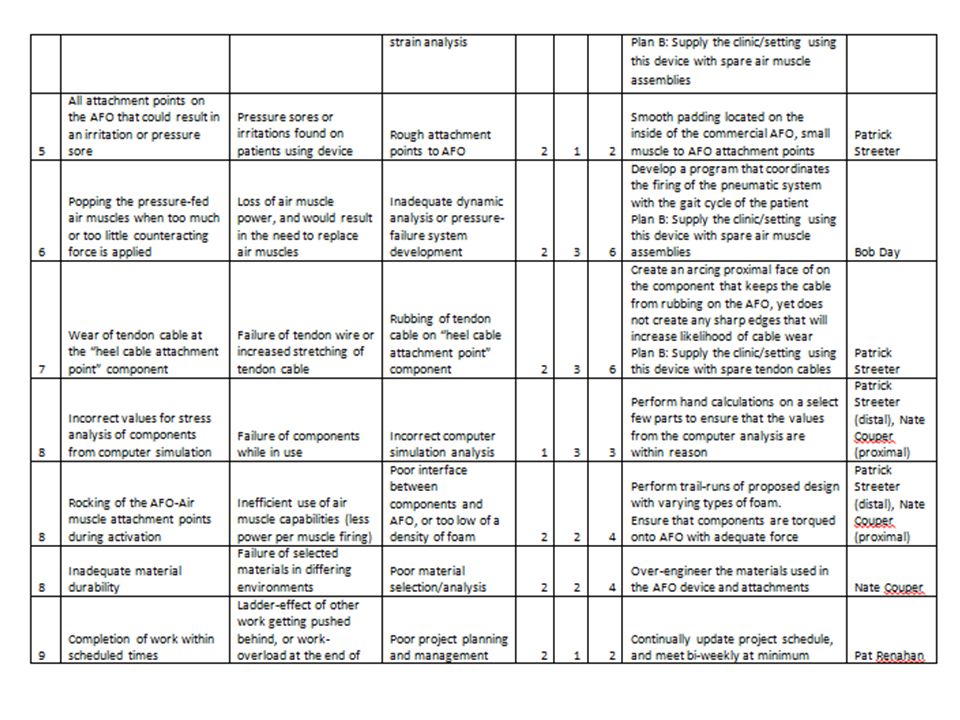
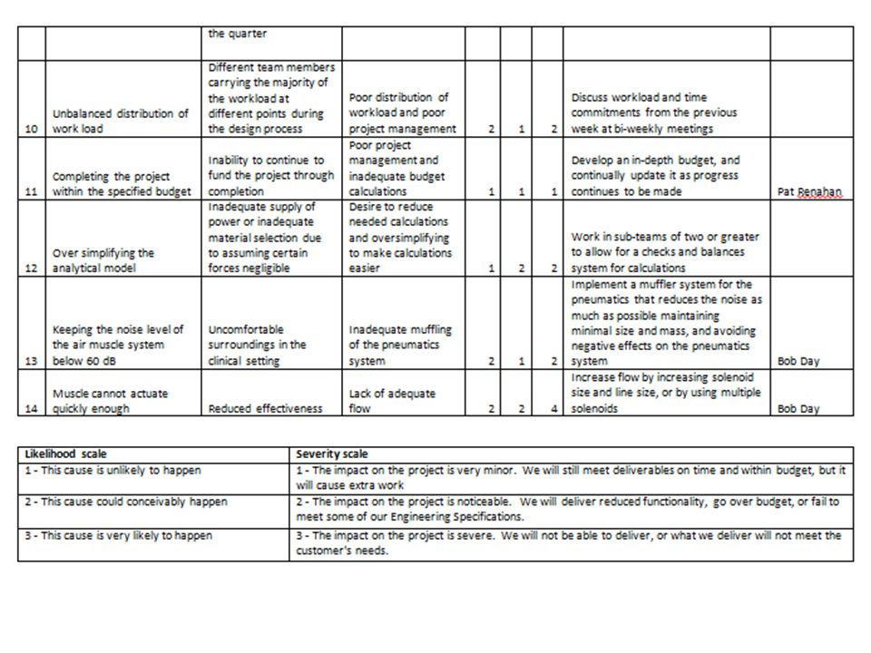
Updated Risk Assessment

41
Bill of Materials

42
Schedule for MSD II Reference EDGE website for working, detailed project schedule: Planning and Execution – Project Plans and Schedules – “Schedule of Action Items” http://edge.rit.edu/edge/P13001/public/Planning %20%26%20Execution

43
Questions?

Similar presentations


, Resistance Seam Welding (RSEW),& Resistance Projection.>")


