Download presentation
Presentation is loading. Please wait.

1
Prof. Enrico Gratton - Lecture 6 - Part 1 Fluorescence Microscopy Instrumentation Light Sources: One-photon and Multi-photon Excitation Applications in Cells Lifetime Imaging Figures acknowledgements: E.D. Salmon and K. Jacobson

2
Confocal microscopy images

3
In the compound microscope the Finite Corrected Objective Forms a Real Image At the Ocular Front Focal Plane: The Primary or Intermediate Image Plane (IIP) Conventional Optics Objective with finite Focal Length (Optical Tube Length, OTL, Typically 160 mm) M ob = OTL/f ob Total Magnification = M ob x M oc = OTL/f ob x 250mm/f oc
 Conventional Optics Objective with finite Focal Length (Optical Tube Length, OTL, Typically 160 mm) M ob = OTL/f ob Total Magnification = M ob x M oc = OTL/f ob x 250mm/f oc")
4
Resolution Limitations of the Human Eye Limits to Accommodation Unresolved Resolved Resolution Test E.D. Salmon Why is the eyepiece necessary?

5
A word about infinity corrected optics and its advantages.

6
Modern microscope component identification Prisms Used to Re-Direct Light In Imaging Path While Mirrors Are Used in Illumination Path E.D.Salmon

7
Camera Camera Adapter Binocular Eyepiece Beam Switch Filter Cube Changer Slot for Analyzer Slot for DIC Prism Objective Nosepiece Objective Stage Condenser: Diaphragm&Turret Centering Focus Field Diaphragm Coarse/Fine Specimen Focus Filters and Diffuser Lamp: Focus, Centering Mirror: Focus and Centering Mirror: Focus and Centering Focus, Centering Trans-Lamp Housing Epi-Lamp Housing Epi-Field Diaphragm Epi-Condenser Diaphragm ShutterFilters& Centering Slot for Polarizer Upright Microscope Stand Body Tube MICROSCOPE COMPONENTS Magnification Changer Identify Major Components And Their Locations And Functions Within Modern Research Light Microscope (See Salmon And Canman, 2000, Current Protocols in Cell Biology, 4.1)
")
8
Key component: the objective Achromats: corrected for chromatic aberration for red, blue Fluorites: chromatically corrected for red, blue; spherically corrected for 2 colors Apochromats: chromatically corrected for red, green & blue; spherically corrected for 2 colors Plan-: further corrected to provide flat field

9
The 3 Classes of Objectives Chromatic and Mono-Chromatic Corrections E.D. Salmon

10
What is numerical aperture (NA)? Image Intensity: I ~ NA obj 2 /M tot 2 Image Lateral Resolution for Corrected Objective: -Fluorescence: r = 0.61 /NA obj -Trans-Illumination: r = /(NA obj + NA cond )
.")
11
Airy Disk Formation by Finite Objective Aperture: The radius of the Airy Disk at the first minimum, r’, occurs because of destructive interference; the diffraction angle, , is given by: sin( ) = 1.22 /D, where D = diameter of objective back aperture E.D. Salmon

12
Lateral Resolution in Fluorescence Depends on Resolving Overlapping “Airy Disks” Rayleigh Criteria: Overlap by r’, then dip in middle is 26% below Peak intensity (2 x/ )NA obj E.D.Salmon
NA obj E.D.Salmon")
13
Resolution is better at shorter wavelengths, higher objective NA or higher condenser NA High NA and/or shorter Low NA and/or longer E.D. Salmon

14
Rayleigh Criterion for the resolution of two adjacent spots: P lim = 0.61 o / NA obj Examples: ( o = 550 nm) Magf(mm) n a NAP lim ( m) (NA cond =NA obj ) high dry 10x161.00150.251.10 40x41.00400.650.42 oil 100x1.61.52611.330.204 63x2.51.5267.51.400.196
 Magf(mm) n a NAP lim ( m) (NA cond =NA obj ) high dry 10x x oil 100x x")
15
Why oil immersion lenses have greater resolution D= 0.61 cos / n(NA) 2 Low power, NA~ 0.25 D~ 8 m Hi, dry, NA~0.5 D~ 2 m Oil immersion, NA~ 1.3 D~0.4 m
 2 Low power, NA~ 0.25 D~ 8 m Hi, dry, NA~0.5 D~ 2 m Oil immersion, NA~ 1.3 D~0.4 m")
16
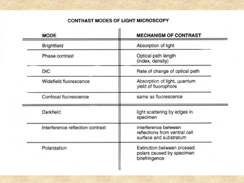
E.D.Salmon Contrast : All the resolution in the world won’t do you any good, if there is no contrast to visualize the specimen.

18
Index of refraction Brightfield Phase contrast Normalized interference Darkfield Brightfield Darkfield Fluorescence

19
The microscope as a filter fluorometer with focusing optics

20
Basic design of the epi fluorescence microscope

21
Common non-laser light sources: arc lamps 504.2 x 2.3450010012V 100W Tungsten- Halogen lamps 4000.5 x 0.2540 00075XBO 75W/2 High- pressure Xenon lamps 100 200 1.0 x 0.3 0.25 x 0.25 30 000 170 000 50 100 HBO 50W/AC HBO 100W/2 High- pressure Mercury lamps Lifetime (h) Arc size h x w (mm) Luminou s density (cd/cm 2 ) Wattage (W) Type From Zeiss
 Arc size h x w (mm) Luminou s density (cd/cm 2 ) Wattage (W) Type From Zeiss")
22
Objectives High transmittance Fluorite lenses: > 350 nm [ok for FURA] Quartz lenses: < 350 nm Employ simple, non plan lenses to minimize internal elements. Negligible auto-fluorescence or solarization [color change upon prolonged illumination]
![Objectives High transmittance Fluorite lenses: > 350 nm [ok for FURA] Quartz lenses: < 350 nm Employ simple, non plan lenses to minimize internal elements.](http://images.slideplayer.com/18/6086403/slides/slide_22.jpg "Negligible auto-fluorescence or solarization [color change upon prolonged illumination].")
23
Maximizing image brightness (B) excitation efficiency ~ (NA) 2 => B ~ (NA) 4 collection efficiency ~ (NA) 2 1 (NA) 4 also B ~ => B ~, for NA ≤ 1.0 M 2 M 2 at high NA,
 excitation efficiency ~ (NA) 2 => B ~ (NA) 4 collection efficiency ~ (NA) 2 1 (NA) 4 also B ~ => B ~, for NA ≤ 1.0 M 2 M 2 at high NA,")
24
Filters

27
Interference filter definitions

28
Filter cube designs employing long- pass emitter filters Filter cube designs employing band- pass emitter filters

29
Multiple Band- Pass Filters From E.D. Salmon

30
Multi-Wavelength Immunofluorescence Microscopy

31
PIXELS The building blocks of CCDs Back thinned CCDs receive light from this side

32
Primary Features of CCD Spatial resolution of the CCD array –Number of Pixels in X and Y –Center to Center Distance of Pixels in microns Full Well Capacity –Related to Physical size and electronic design –Determines Maximum Signal level possible Quantum Efficiency/Spectral Range –Determines the usefulness of the camera –Major influence on exposure time Camera Noise –The limiting feature in low light applications –Influenced by Readout Speed / Readout Noise –Influenced by Dark Current / Time CCD Chip Design –Influences Total Frame Rate Exposure time plus Readout time –Total Photon Efficiency Quantum Efficiency and Exposure Cycle B. Moomaw, Hamamatsu Corp.,

33
Types of CCD Detectors CCD Cameras - 3 Primary Designs B. Moomaw, Hamamatsu Corp.

34
Improvements in Interline CCDs Effective Q.E. was greatly increased by Microlens technology. Old IT CCD Single microlens added Open window Input light Microlens B. Moomaw, Hamamatsu Corp.

35
Latest Improvement to Interline CCDs Latest double micro lens structure improved the CCD open ratio up to 80% and Q.E. to over 70%! Input light Double lens structure added B. Moomaw, Hamamatsu Corp.

36
Noise as a function of incident camera illumination (Camera Noise =10 electron, QE =0.4) N Camera » N Signal N Signal » N camera S/N = S/N Camera S/N = S/N Signal = S
 N Camera » N Signal N Signal » N camera S/N = S/N Camera S/N = S/N Signal = S")
37
COMMON SOURCES OF AUTOFLUORESCENCE Autofluorescent Source Typical Emission Wavelength (nm) Typical Excitation Wavelength (nm) Flavins 520 to 560 380 to 490 NADH and NADPH 440 to 470 360 to 390 Lipofuscins 430 to 670 360 to 490 Advanced glycation end-products (AGEs) 385 to 450 320 to 370 Elastin and collagen 470 to 520 440 to 480 Lignin 530 488 Chlorophyll 685 (740) 488 From Biophotonics International
 Typical Excitation Wavelength (nm) Flavins 520 to to 490 NADH and NADPH 440 to to 390 Lipofuscins 430 to to 490 Advanced glycation end-products (AGEs) 385 to to 370 Elastin and collagen 470 to to 480 Lignin Chlorophyll 685 (740) 488 From Biophotonics International")
38
Photobleaching Photochemical lifetime: fluorescein will undergo 30-40,000 emissions before bleaching. (Qy bleaching ~ 3E-5) At low excitation intensities, photobleaching occurs but at lower rate. Bleaching is often photodynamic--involves light and oxygen.
 At low excitation intensities, photobleaching occurs but at lower rate. Bleaching is often photodynamic--involves light and oxygen..")
39
Parameters for Maximizing Sensitivity Use High Objective NA and Lowest Magnification: I fl ~ I il NA obj 4 /M tot 2 -Buy the newest objective: select for best efficiency Close Field Diaphragm down as far as possible Use high efficiency filters Use as few optical components as possible Match magnification to camera resolution: M Max = 3*Pixel Size of Detector/Optical Resolution E.g.: 3*7 m/[0.6 *520nm/1.4] = 91X Reduce Photobleaching Use High Quantum Efficiency Detector in Camera Adapted from E.D.Salmon
![Parameters for Maximizing Sensitivity Use High Objective NA and Lowest Magnification: I fl ~ I il NA obj 4 /M tot 2 -Buy the newest objective: select for best efficiency Close Field Diaphragm down as far as possible Use high efficiency filters Use as few optical components as possible Match magnification to camera resolution: M Max = 3*Pixel Size of Detector/Optical Resolution E.g.: 3*7 m/[0.6 *520nm/1.4] = 91X Reduce Photobleaching Use High Quantum Efficiency Detector in Camera Adapted from E.D.Salmon](http://images.slideplayer.com/18/6086403/slides/slide_39.jpg "Parameters for Maximizing Sensitivity Use High Objective NA and Lowest Magnification: I fl ~ I il NA obj 4 /M tot 2 -Buy the newest objective: select for best efficiency Close Field Diaphragm down as far as possible Use high efficiency filters Use as few optical components as possible Match magnification to camera resolution: M Max = 3*Pixel Size of Detector/Optical Resolution E.g.: 3*7 m/[0.6 *520nm/1.4] = 91X Reduce Photobleaching Use High Quantum Efficiency Detector in Camera Adapted from E.D.Salmon")
40
Live Cell Considerations Minimize photobleaching and photodamage (shutters) Use heat reflection filters for live cell imaging Image quality: Maximize sensitivity and signal to noise (high transmission efficiency optics and high quantum efficiency detector) Phase Contrast is Convenient to Use with Epi- Fluorescence –Use shutters to switch between fluorescence and phase –Phase ring absorbs ~ 15% of emission and slightly reduces resolution by enlarging the PSF Adapted from E.D. Salmon

41
Defining Our Observation Volume: One- & Two-Photon Excitation. 1 - Photon 2 - Photon Approximately 1 um 3 Defined by the wavelength and numerical aperture of the objective Defined by the pinhole size, wavelength, magnification and numerical aperture of the objective

42
Advantages of two-photon excitation 3-D sectioning effect Absence of photo bleaching in out of focus regions Large separation of excitation and emission No Raman from the solvent Deep penetration in tissues Single wavelength of excitation for many dyes High polarization Brad Amos MRC, Cambridge, UK

43
Why confocal detection? Molecules are small, why to observe a large volume? Enhance signal to background ratio Define a well-defined and reproducible volume Methods to produce a confocal or small volume (limited by the wavelength of light to about 0.1 fL) Confocal pinhole Multiphoton effects 2-photon excitation (TPE) Second-harmonic generation (SGH) Stimulated emission Four-way mixing (CARS) (not limited by light, not applicable to cells) Nanofabrication Local field enhancement Near-field effects
 Confocal pinhole Multiphoton effects 2-photon excitation (TPE) Second-harmonic generation (SGH) Stimulated emission Four-way mixing (CARS) (not limited by light, not applicable to cells) Nanofabrication Local field enhancement Near-field effects.")
44
How does one create an observation volume and collect the data? Two-Photon, Scanning, FCS Microscope Argon Ion Laser Titanium Sapphire Laser Sample Microscope Computer Detector Mode-Locked 150 fs pulses Dichroic BS Em1 Em2 Mirror Scanner

45
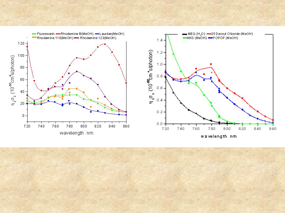
Laser technology needed for two-photon excitation Ti:Sapphire lasers have pulse duration of about 100 fs Average power is about 1 W at 80 MHz repetition rate About 12.5 nJ per pulse (about 125 kW peak-power) Two-photon cross sections are typically about =10 -50 cm 4 sec photon -1 molecule-1 Enough power to saturate absorption in a diffraction limited spot n a Photon pairs absorbed per laser pulse p Average power pulse duration f laser repetition frequency A Numerical aperture Laser wavelength d cross-section
 Two-photon cross sections are typically about = cm 4 sec photon -1 molecule-1 Enough power to saturate absorption in a diffraction limited spot n a Photon pairs absorbed per laser pulse p Average power pulse duration f laser repetition frequency A Numerical aperture Laser wavelength d cross-section")
46
Wavelength (nm) 800600400 Laser 2-photon excem Raman Intensity
 Laser 2-photon excem Raman Intensity")
48
General References Salmon, E. D. and J. C. Canman. 1998. Proper Alignment and Adjustment of the Light Microscope. Current Protocols in Cell Biology 4.1.1-4.1.26, John Wiley and Sons, N.Y. Murphy, D. 2001. Fundamentals of Light Microscopy and Electronic Imaging. Wiley-Liss, N.Y. Keller, H.E. 1995. Objective lenses for confocal microscopy. In “Handbook of biological confocal microsocpy”, J.B.Pawley ed., Plenum Press, N.Y.

49
On line resource: Molecular Expressions, a Microscope Primer at: http://www.microscopy.fsu.edu/primer/ index.html http://www.microscopy.fsu.edu/primer/ index.html

Similar presentations


 iris diaphragm.>")
 11/16/2010 Presented by: Mathilde Bonnemasison Leia Shuhaibar Steve Pirnie Ronghua (Ronnie) Yang Neil MAA, Juskaitis.>")
, Phase Contrast, DIC 3.Newer.>")


 : separation of close objects, light wavelength NA, numerical aperture 2. Contrast : distinction of objects from background “light field”>")


 Wave Optics Diffraction & Interference Christiaan Huygens (1629 - 1695)>")


http://micro.magnet.fsu.edu/primer/ anatomy/anatomy.htmlhttp://micro.magnet.fsu.edu/primer/ anatomy/anatomy.html 2)http://micro.magnet.fsu.edu/primer/>")

