Download presentation
Presentation is loading. Please wait.

1
DPCL Solid State Device Discrete Control Lecture

2
Discrete Input – Output, I/O All devices/control in this course have been “analog” measurements; level, flow, temperature etc. Discrete control implies two stable “states”, open-closed, on-off, etc.

3
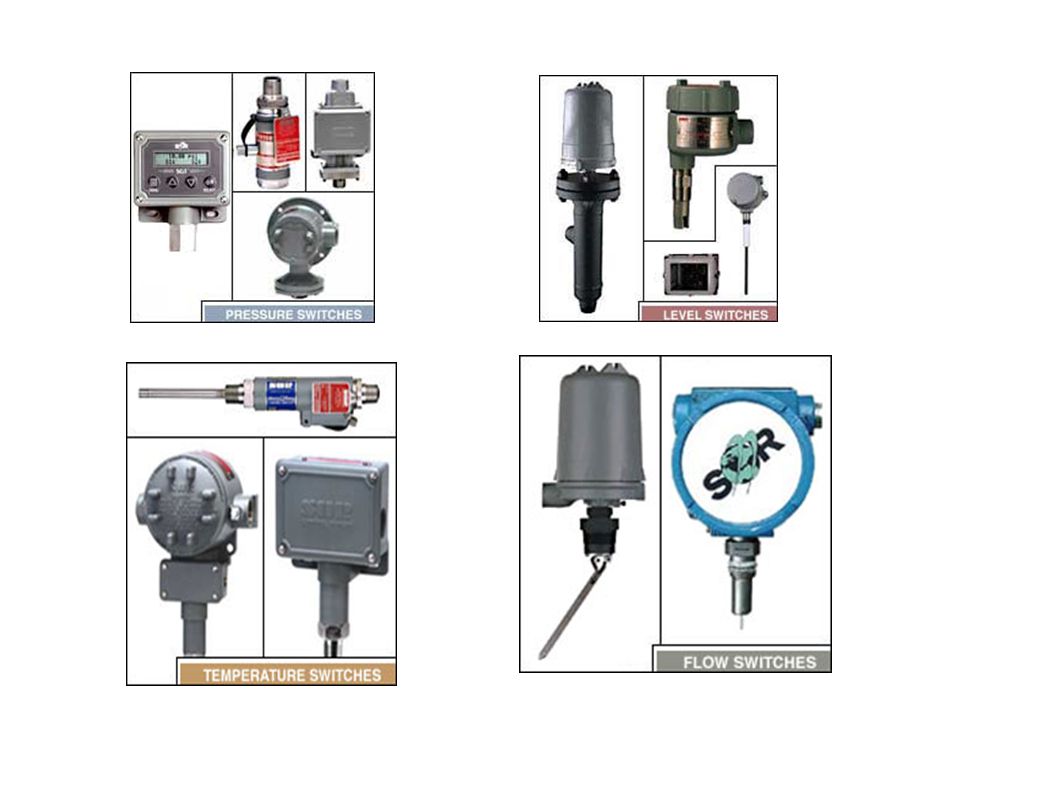
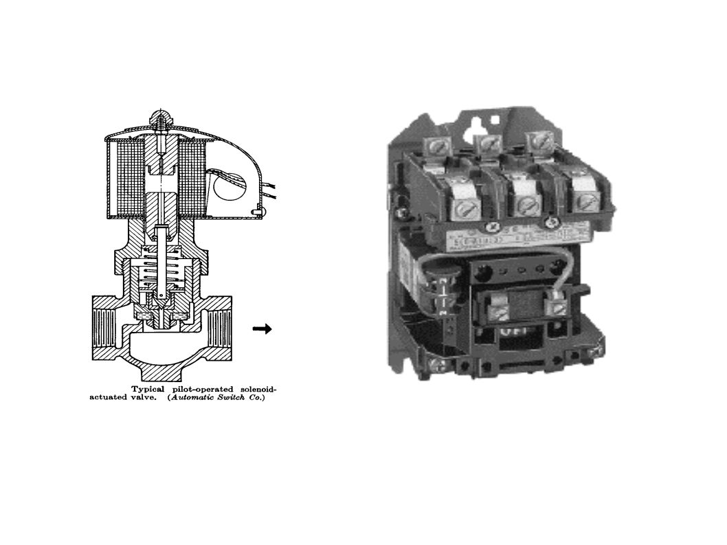
Inputs-Outputs Inputs are push buttons, various switches that sense physical conditions, such as pressure, level, temperature, proximity or limit etc. Outputs are used to control “on-off” devices such as solenoid valves, motors, relays, contactors etc.

4
Terms used to represent discrete behavior Binary 01 Voltage0 to 1.5 V3.5 to 5 V(or opposite) LogicFalseTrue SwitchOFFON LevelLowHigh
 LogicFalseTrue SwitchOFFON LevelLowHigh")
5
Inputs – Switch Configurations SPST Single Pole Single Throw: SPDT Single Pole Double Throw: DPST Double Pole Single Throw: DPDT Double Pole Double Throw:

6
Switches Process Switches are frequently used as safety interlocking devices. Interlock – shutdown system Pressure, level, temperature, flow vibration etc. The safe way to wire these devices is to assume that the normal process condition will result in a closed switch that is there will be current flow to the device during “normal” operation. This way wiring failures will “fail safe”, resulting in the alarmed or interlocked condition.

9
Discrete I/O Interfacing The control equipment, either a PLC or a control system such as DeltaV Distributed Control System, DCS, requires its internal circuitry to be interfaced with these industrial electrical or electromechanical devices. 5V dc TTL (Transistor Transistor Logic) signals for this interface. Isolate computer wiring with “field” wiring, via optical or transformer coupling.
 signals for this interface. Isolate computer wiring with field wiring, via optical or transformer coupling..")
10
Discrete I/O Interfacing The “field” or machine wiring may be either AC or DC powered. Examples of AC and DC interface Input Output Circuits shown in notes.

11
Optical I/O Isolation

12
SSR - Solid State Relays Solid-state relays (SSRs) control load currents through solid-state switches such as triacs, SCRs, or power transistors. These elements are controlled by input signals coupled to the switched devices through isolation mechanisms such as transformers, reed relays, or optoisolators. Sometimes called thyristors. The loads or switched devices are electrical power consuming devices, contactors, transformers, etc.

13
SSR - Solid State Relays Silicon controlled rectifiers (SCRs) 3 terminal device; phase control. Phase control, continuously variable power is obtained by controlling the conduction period of a thyristor or SCR. SCRs can be used singly for half-wave power control, or in combination for full-wave control. Light dimmer control is a common example. Used to control the amount of voltage and current to the load from near zero to maximum. This is a very non-linear relationship and may cause overshoot if not linearized.

15
SCR Phase Conduction/Firing resistive load, ½ wave rectified

16
Triac Bidirectional triode thyristor (triac), 2 SCRs in parallel.One SCR will conduct the positive half- cycle and the other will conduct the negative half- cycle. Discrete control only.

17
Triac fired by either positive or negative gate pulse. Gate pulse can be momentary, the triac will remain in conduction until the conditions for commutation are satisfied, i.e. reversed polarity. Zero crossing shown.

18
Inductive Loads Current and voltage are not in phase. Triac can conduct current in both directions, it has only a brief interval during which the sine wave current is passing through zero to recover and revert to the blocking state. Blocking voltage must appear across the triac to switch it off. If this voltage appears too rapidly, the triac will resume conduction and control is lost. In order to achieve control with certain inductive loads, the rate of rise in voltage (dV/dt) must be limited by a series RC network placed in parallel with the power triac. Called a “Snubber”
 must be limited by a series RC network placed in parallel with the power triac. Called a Snubber .")
19
Switching inductive loads with an SCR will result in a high dv/dt transient due to collapsing the stored magnetic filed in the inductor. This can damage the SCR. Adding a “Snubber”, a RC series network in parallel with the SCR can reduce these transients. The following SPICE simulated circuits show the effect. Notice the reduced dv/dt.

20
With Snubber

21
Without Snubber

22
Transformer Loads Ferromagnetic materials are have a non-linear magnetization characteristics. At high magnetic fields, H the magnetic flux, B, will saturate. When H is reduced to zero, the ferromagnetic material retains a certain magnetic flux B, called the residual flux density. This can create a surge when the SSR is switched. In order to reduce the surge in the first half-period, a “peak switching” relay is used. The peak switching relay never performs the actual switching function until the first peak voltage is reached. After the first half-period it is works the same as a zero switching relay.

23
DC SSR Applications When DC inductive loads, solenoid valves etc. are switched off the magnetic field stored in the coil will collapse. All this energy will be released across the contacts or circuit if not protected. Spark will occur Without protection, device can be damaged. Solution: Wire diodes across the load or circuit to protect the surge.

25
With diode

26
Without diode

27
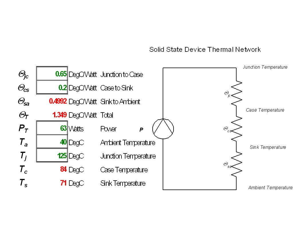
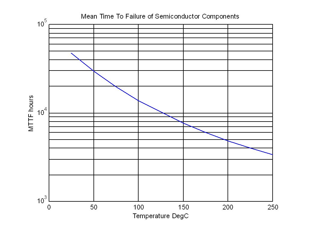
Thermal Design Considerations A major design concern for SSRs is heat removal. Semiconductor reliability is inversely proportional to the operating temperature. In order to transfer the heat dissipated by the device, device is mounted to a finned metal plate - heat sink. The semiconductor thermal ratings are the junction temperature and the “thermal resistances”. For silicon devices the junction temperature is < 125 DegC. The thermal resistances are between Junction and the case Case and the heat sink Heat sink and the ambient air

29
Enclosure Ventilation Use forced air to remove the heat. Calculate the volume of air required: Where V is the fan capacity in ft^3/minute P is the Power in Kilowatts T 1 is the inlet temperature in degR T 2 is the outlet temperature in degR; that is the temperature inside the enclosure

30
Semiconductor Reliability a function of the Arrhenius Model E = Activation Energy = Failure Rate k = Boltzmann’s constant 8.61x10^-5 eV/degK T = Temperature in DegK MTTF = 1/

Similar presentations