Download presentation
Presentation is loading. Please wait.

1
Chapter 10 Error Detection and Correction
Types of Errors Detection Correction

2
Basic concepts Networks must be able to transfer data from one device to another with complete accuracy. Data can be corrupted during transmission. For reliable communication, errors must be detected and corrected. Error detection and correction are implemented either at the data link layer or the transport layer of the OSI model.

3
Types of Errors

4
Single-bit error

5
Single bit errors are the least likely type of errors in serial data transmission because the noise must have a very short duration which is very rare. However this kind of errors can happen in parallel transmission. Example: If data is sent at 1Mbps then each bit lasts only 1/1,000,000 sec. or 1 μs. For a single-bit error to occur, the noise must have a duration of only 1 μs, which is very rare.

6
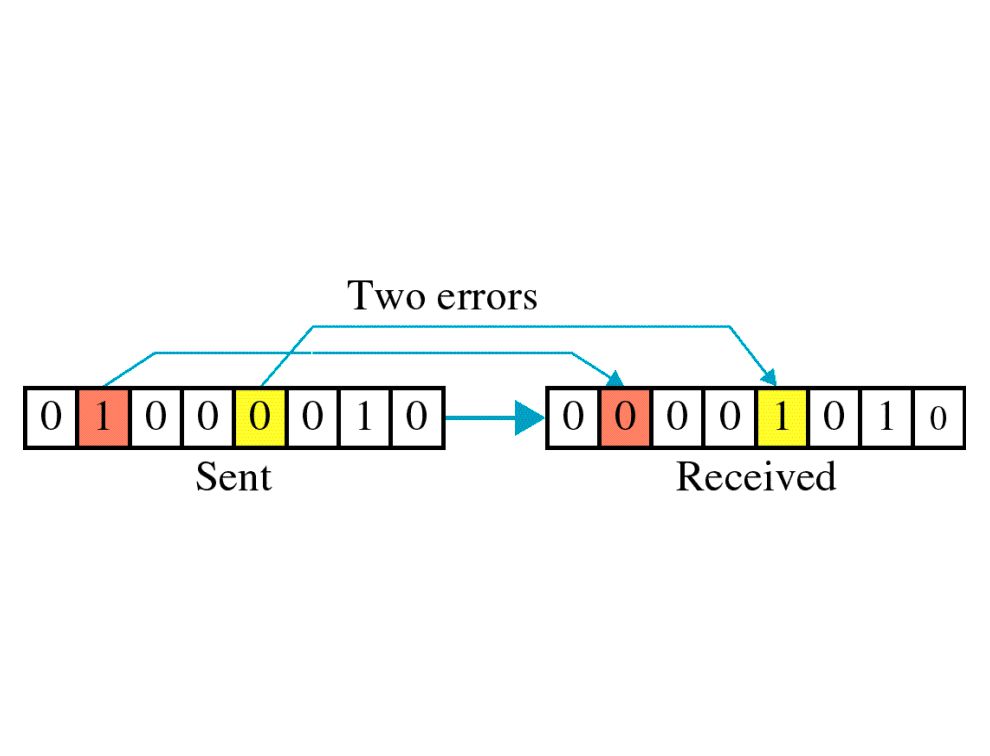
Burst error

8
The term burst error means that two or more bits in the data unit have changed from 1 to 0 or from 0 to 1. Burst errors does not necessarily mean that the errors occur in consecutive bits, the length of the burst is measured from the first corrupted bit to the last corrupted bit. Some bits in between may not have been corrupted.

9
Burst error is most likely to happen in serial transmission since the duration of noise is normally longer than the duration of a bit. The number of bits affected depends on the data rate and duration of noise. Example: If data is sent at rate = 1Kbps then a noise of 1/100 sec can affect 10 bits.(1/100*1000) If same data is sent at rate = 1Mbps then a noise of 1/100 sec can affect 10,000 bits.(1/100*106)
 If same data is sent at rate = 1Mbps then a noise of 1/100 sec can affect 10,000 bits.(1/100*106)")
10
Error detection Error detection means to decide whether the received data is correct or not without having a copy of the original message. Error detection uses the concept of redundancy, which means adding extra bits for detecting errors at the destination. Make sense of message.

11
Redundancy

12
Four types of redundancy checks are used in data communications

13
Vertical Redundancy Check
VRC

14
Performance It can detect single bit error
It can detect burst errors only if the total number of errors is odd.

15
Longitudinal Redundancy Check
LRC

16
Performance LCR increases the likelihood of detecting burst errors.
If two bits in one data units are damaged and two bits in exactly the same positions in another data unit are also damaged, the LRC checker will not detect an error.

17
VRC and LRC

18
Cyclic Redundancy Check
CRC

19
Cyclic Redundancy Check
Given a k-bit frame or message, the transmitter generates an n-bit sequence, known as a frame check sequence (FCS), so that the resulting frame, consisting of (k+n) bits, is exactly divisible by some predetermined number. The receiver then divides the incoming frame by the same number and, if there is no remainder, assumes that there was no error.
, so that the resulting frame, consisting of (k+n) bits, is exactly divisible by some predetermined number. The receiver then divides the incoming frame by the same number and, if there is no remainder, assumes that there was no error.")
20
Binary Division

21
Polynomial

22
Polynomial and Divisor

23
Standard Polynomials

24
Checksum

25
At the sender The unit is divided into k sections, each of n bits.
All sections are added together using one’s complement to get the sum. The sum is complemented and becomes the checksum. The checksum is sent with the data

26
At the receiver The unit is divided into k sections, each of n bits.
All sections are added together using one’s complement to get the sum. The sum is complemented. If the result is zero, the data are accepted: otherwise, they are rejected.

27
Performance The checksum detects all errors involving an odd number of bits. It detects most errors involving an even number of bits. If one or more bits of a segment are damaged and the corresponding bit or bits of opposite value in a second segment are also damaged, the sums of those columns will not change and the receiver will not detect a problem.

28
Error Correction It can be handled in two ways:
receiver can have the sender retransmit the entire data unit. The receiver can use an error-correcting code, which automatically corrects certain errors.

29
Single-bit error correction
To correct an error, the receiver reverses the value of the altered bit. To do so, it must know which bit is in error. Number of redundancy bits needed Let data bits = m Redundancy bits = r Total message sent = m+r The value of r must satisfy the following relation: 2r ≥ m+r+1

30
Error Correction

31
Hamming Code

32
Hamming Code

33
Hamming Code

34
Example of Hamming Code

35
Single-bit error

36
Error Detection

Similar presentations