Download presentation
Presentation is loading. Please wait.

1
Electron Microscope Sarah, David, Jóhann

2
The electron source Thermionic emission Field emission Wolfram
LaB6 [CeB6 can be used instead] Field emission Cold Field Schottky Lanthanium hexaboride

3
Thermionic emission Thermal energy is used to allow the electrons overcome the work function, releasing them to form an electron beam. Requires material with a very high melting point (Wolfram, 3695 K) or a low work function (LaB6, 2.4 eV) Richardson’s Law: 𝐽=𝐴𝐺 𝑇 2 𝑒 − Φ 𝑘 𝐵 𝑇 Where J is the current density in A/m2, T is in Kelvin, and AG is Richardson’s constant (A/m2K2)
 or a low work function (LaB6, 2.4 eV) Richardson’s Law: 𝐽=𝐴𝐺 𝑇 2 𝑒 − Φ 𝑘 𝐵 𝑇. Where J is the current density in A/m2, T is in Kelvin, and AG is Richardson’s constant (A/m2K2)")
4
Field emission The emission of electrons induced by an electrostatic field The theory is described approximately by the Fowler-Nordheim equations, which strictly speaking apply only to field emissions from bulk metals. A prime example of electron tunneling

5
Field emission, cont. In order to function properly at ambient temperatures, the surface must be contamination and oxide free – this is achieved by operating under high vacuum conditions (<10-11 Torr) – called cold field emission. A poorer vacuum can be used by heating the tip, and the thermal energy also assists in electron emission. 10^-11 Torr = 1.33e-9 Pa
 – called cold field emission. A poorer vacuum can be used by heating the tip, and the thermal energy also assists in electron emission. 10^-11 Torr = 1.33e-9 Pa.")
6
These ZrO coated electron guns are called Schottky emitters.
In these cases, the surface is covered with ZrO to improve the emission characteristics. These ZrO coated electron guns are called Schottky emitters. Walter H. Schottky, german physicist ( ) ZrO supposedly increases conductivity at high temperatures
 ZrO supposedly increases conductivity at high temperatures.")
7
Electron-beam lithography
Using a focused beam of electrons to draw custom shapes on an electron sensitive film. [“exposing”] This changes the solubility of the affected area, enabling selective removal of either the exposed or non-exposed areas by solvent immersion. [“developing”] Primary advantage of e-beam lithography is the custom pattern with <10 nm resolution, although due to its low throughput, usage is limited. Photomask fabrication, low volume production of semiconductor devices, R & D

8
Electron Sources Thermionic sources are sufficient when high resolution is not required. When it is, field electron emission sources are preferred due to their lower energy spread and enhanced brightness. Within the field emissions, thermal assisted is preferred over cold, despite the former’s slightly larger beam size, due to greater stability over long periods of time. Several hours.

9
Throughput Minimum time to expose a given area for a given dose:
𝐷∗𝐴=𝑇∗𝐼 Where T is the time to expose the object, I is the beam current, D is the dose and A is the area exposed.

10
Throughput, example Assume: Exposure area (A) of 1 cm2 Dose (D) of 10-3 C/cm2 Beam current (I) of 10-9 A 𝑇= 𝐷∗𝐴 𝐼 T=106 s (approximately 11.5 days) For the 700 cm2 surface of a 300 mm silicon wafer, minimum writing time is just over 22 years.
 of 1 cm2 Dose (D) of 10-3 C/cm2 Beam current (I) of 10-9 A 𝑇= 𝐷∗𝐴 𝐼 T=106 s (approximately 11.5 days) For the 700 cm2 surface of a 300 mm silicon wafer, minimum writing time is just over 22 years.")
11
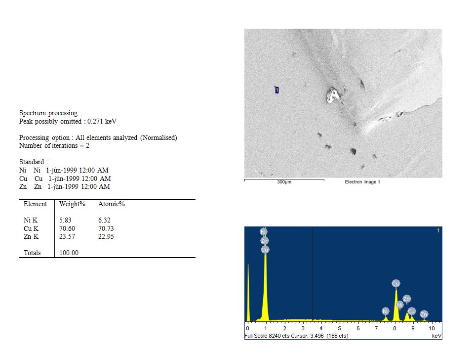
Quantitative Analysis
In order to do quantitative analysis, the surface of the material being measured must be flat. X-rays must travel through the material above them in order to be detectable – the greater the distance, the more of an effect this has on the energy. In order for this effect to be consistent, the distance traveled through the material must remain constant – which is achieved by having a flat surface.

12
Qualitative Analysis The detector for the X-rays involves the use of a silicon crystal. The photons hit the crystal, releasing electrons which are then counted. Counting these electrons takes time, which means there is a speed vs. accuracy tradeoff.

13
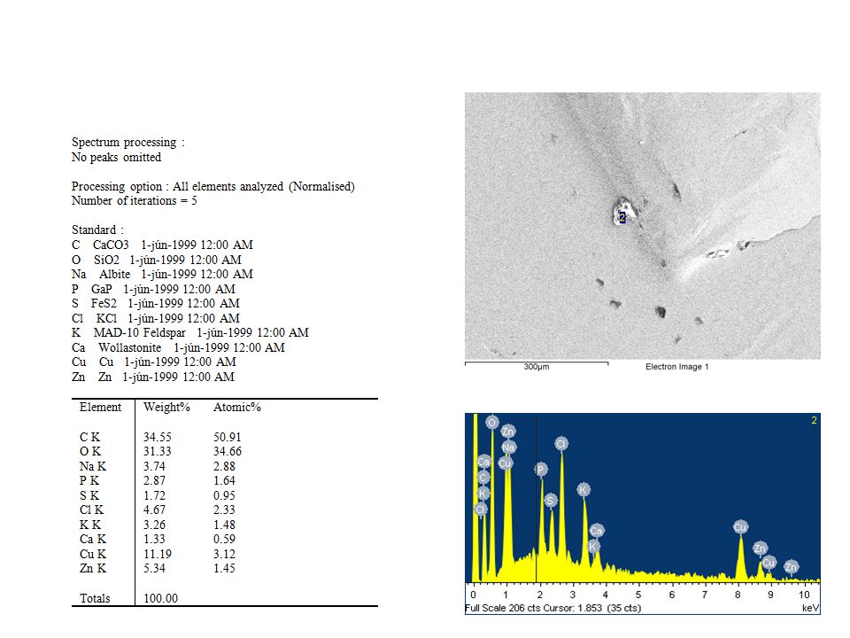
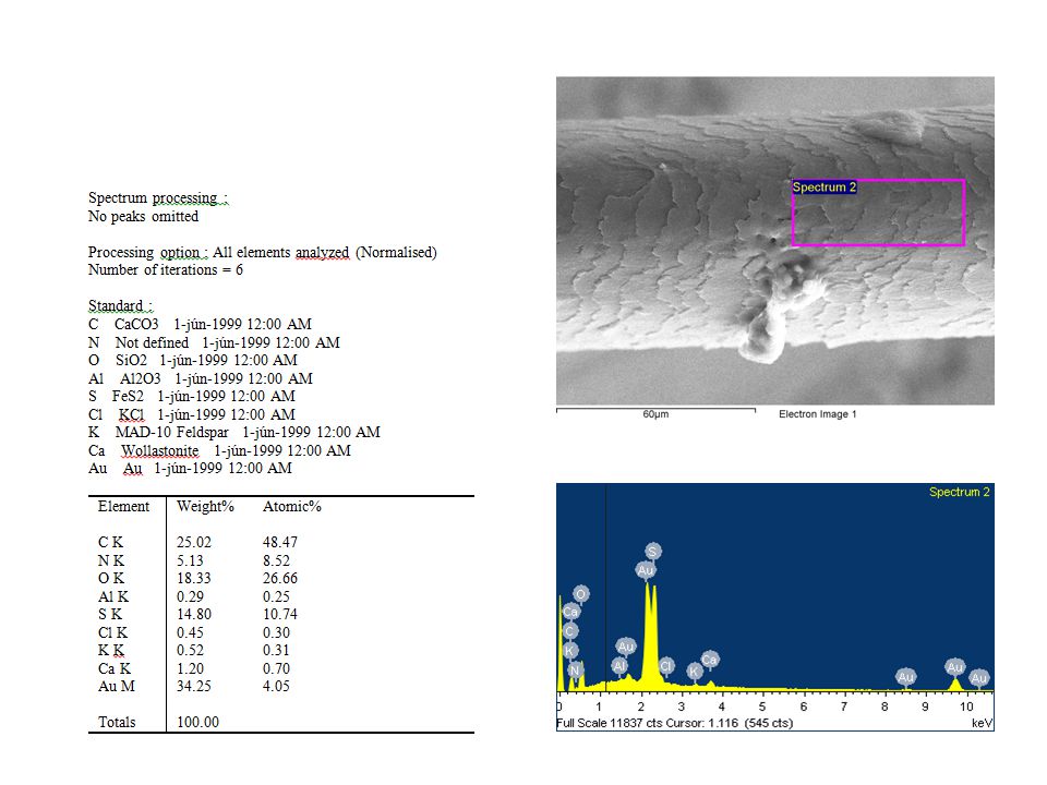
Qualitative Analysis, cont.
The spectra are a combination of two things – the characteristic peaks used for identifying elements, and the continuous background spectra, which ranges from zero up to the beam voltage. The background radiation is a result of the deceleration of beam electrons as they travel through the material.

18
2D representation of chemical composition along a line

Similar presentations


>")


 HITESH KUMAR GUPTA(09320) CHANDAN SINGH(09260) SCANNING ELECTRON MICROSCOPE MATERIAL SCIENCE ASSIGNMENT.>")


