Download presentation
Presentation is loading. Please wait.

1
Electronic voting machines
From assigned papers: What did you learn? What struck you as most interesting? Most troubling? Slides that follow bring additional perspective

2
October 29, 2006

3
Halloween 2003

4
System reliability: freedom at stake?
Simple to build a voting machine that records punched holes, right? What if they aren’t punched exactly right? Is such a vote invalid, or can someone determine what voter intended? There is much more to voting than tabulating punched cards; there is an entire system to consider + political implications. Results combined with others in hierarchy reaching state, national levels. Accuracy depends on every step along the way. Any errors in transmitting or recording will fatally corrupt the results. Checks and balances vital to having trust in the system. Major parties allowed to examine all voting materials, inspect voting machines, certify that votes are accurately counted and reported. Intent: reduce fraud, while preserving privacy and anonymity of each vote. Source: “Embedded elections”, Ed Nisley, Dr. Dobb’s Journal, April 2001 (Written shortly after the hanging chad fiasco of the 2000 election.)
")
5
Embedded elections As process changes with technology, can observation still take place? Can we maintain the critical checks and balances? Consider mechanical voting machines: Levers on front, mechanical counters on back, interconnected by rods. Powered by same handle that closes privacy curtain. Inspectors verify that dials read zero at start, then record totals at end. How might one affect final tally on such a machine? Gears can be shaved to skip counts, levers slightly bent, etc. Election inspectors are volunteers, not engineers or forensic experts. The machines are not torn down for a complete check before election. Inspectors can only verify that machine seems to be working.

6
Embedded elections, cont.
If mechanical machines are bad, all-electronic machines are worse. Called “Direct-Recording Electronic Voting Machines” in the jargon. There is nothing to inspect, no way to verify their correct operation. Self-test routines can be faked, checksums made up, and any desired validation results processed on the fly. And there’s no possibility of a recount independent of the machine, simply because the votes exist only as insubstantial electronic blips stored within the machine. Opportunities for trickery don’t end with the voting machine and, I fear, provide the most opportunity for clandestine manipulation. Because the voting results become progressively more concentrated as they go from precinct to county to state to nation, it should become more difficult to gain access to the computers doing the tallying, the software in those machines should be more open to inspection, and the process should have some verification and cross-checking. Nothing, it seems, could be further from the truth.

7
Embedded elections, cont.
Suppose a new all-electronic voting system is being designed. Consider the challenge of getting specs up front. Arcane local laws create constraints that must all be considered. Suppose outcome is unlikely but possible – how can you demonstrate that machines are functioning correctly? Options: Record every vote? Must be anonymous: can’t store name, ID, or even store them in sequence. Emit a ticket or receipt for voter? Prohibited in some jurisdictions: voters can’t be paid for their votes Engineers usually wrestle with physical laws; less likely to have mindset for a successful design in a field with “tangled legalisms and the potential for outright fraud.”

8
Embedded elections, cont.
But, wait! There’s more! Some 20 year old mechanical voting machines still work just fine. What are the chances that any machine designed today is useful, functional, or repairable 20 years from now? Think about trying to make computers work today from 20 years ago. And what about the digital vandals that write worms, viruses? Rare in embedded world – not much payback for disabling a few elevators. Suppose the US established a single standard for voting machines; would this be enticing to some? Plenty of groups who would want to influence a US presidential election; some have immense resources. What about access and opportunity? Voting machines locked up when not in use; under control of local officials. Are local officials ever convicted on charges of corruption? Hmmm….

9
Embedded elections, cont.
“The system designers will simplify the method of the crime, too.” Features: downloadable updates, revisable features, and online maintenance. Probably web-enabled to boot. Possible hardware security holes: JTAG connector, ROM socket, flash memory, serial port It should be obvious that displaying one value on an LCD, printing a second on paper, transmitting a third to the central tally, and creating an audit trail with a fourth isn’t all that difficult. You cannot verity data using the same circuitry that stores it, digital signatures notwithstanding! If an attacker can replace the program, all things are possible and all checks will balance. Assume that an attacker has four or eight or twelve years, an unlimited budget, world-class experts on call, sample systems to experiment with, and all the documentation and source code. Think they can pull off an attack? Well, do unfunded groups with low resources bring down nominally high-security systems even today?

10
Embedded elections, cont.
Even better, nobody will ever know. The attackers need not force a win by percent of the vote. Just a few points one way or the other, not a landslide, and no one will ever be the wiser. Those printed audit records (or whatever safeguards you design into your voting machine) will never be consulted, as there won’t be any reason to verify the “obviously correct” results. Or maybe everybody will know. Suppose every single voting machine in the US crashes at high noon (local or UTC, take your pick) on election day? Or the Webbish vote collection system seizes up under a Denial of Service attack? Or the final tally shows Mickey Mouse as the clear winner? Need I go on? Remember, the attackers have an unlimited budget, unlimited expertise, all the source code, complete physical access for years, and may choose any of several desirable (to them) outcomes. Tell me how you’d secure those systems, all the way from the voter’s fingertips to the national media. I don’t believe those safeguards will work, not one little bit. Be very afraid.
 will never be consulted, as there won’t be any reason to verify the obviously correct results. Or maybe everybody will know. Suppose every single voting machine in the US crashes at high noon (local or UTC, take your pick) on election day Or the Webbish vote collection system seizes up under a Denial of Service attack Or the final tally shows Mickey Mouse as the clear winner Need I go on Remember, the attackers have an unlimited budget, unlimited expertise, all the source code, complete physical access for years, and may choose any of several desirable (to them) outcomes. Tell me how you’d secure those systems, all the way from the voter’s fingertips to the national media. I don’t believe those safeguards will work, not one little bit. Be very afraid.")
11
Chapter 8: Design principles
You’ve experienced challenges of writing real-time software. Chapter 8 focuses on design principles for RTOS code. You should apply these principles in Lab 8 application code. Note that principles are not hard and fast rules; sometimes you have to break them to get your system to work. What then is purpose of “rules”? Serve as a useful guide. You should realize that violations are potentially dangerous. Rethink design – make sure there isn’t a better way of doing it.

12
Challenges of real-time code
How does 425 programming differ from other code you’ve written? In general, why is specification for real-time software more difficult than for other software? Besides specifying the actions of the system (input X produces output Y), The response time of each action must be specified, and The criticality of each deadline must be specified. Can any deadlines be missed? What fraction of deadlines can be missed? Hard vs. soft real-time systems; flexibility in meeting deadlines.
, The response time of each action must be specified, and. The criticality of each deadline must be specified. Can any deadlines be missed What fraction of deadlines can be missed Hard vs. soft real-time systems; flexibility in meeting deadlines.")
13
Example: Importance of knowing hardware
Suppose system has 9600 bps data connection. Do you get an interrupt for arrival of each byte, or is DMA used? If no DMA, processor will be interrupted ~1200 times per second. Can your processor handle it? What is the overhead of the ISR each time through? What fraction of CPU time will be spent servicing the interrupt? Is there enough CPU time left over to do other critical processing? What kinds of things do you need to know to answer these questions? Characteristics of all ISRs and tasks in the system. Details about hardware setup, rate of incoming data, etc.

14
Factors to consider Efficiency of application code CPU clock frequency
algorithms and data structures used compiler efficiency CPU clock frequency System (RTOS) overhead: time to execute required functions Predicted worst case event frequency, arrival rate Very difficult to know all these factors without coding it up and seeing what you get. Important: mockups, prototypes, proof-of-concept implementations.
 overhead: time to execute required functions. Predicted worst case event frequency, arrival rate. Very difficult to know all these factors without coding it up and seeing what you get. Important: mockups, prototypes, proof-of-concept implementations.")
15
Relevant article IEEE Computer, July 2005
Edward Lee, assoc. chair of EE/CS dept. at Berkeley argues that CS should be reinvented. Core abstractions must be modified to embrace time. Computer architectures must deliver precisely timed behaviors. Prog. languages must embrace time and concurrency in core semantics. Virtual machines must rely less on just-in-time compilation. Memory management techniques must account for timing constraints. Software eng. must allow specification & analysis of temporal dynamics. Power management techniques must rely less on clock speed scaling. Networking techniques must provide time concurrence. Why? To achieve precise timeliness in a networked embedded system, “an absolutely essential goal.”

16
Two management challenges
How do you manage the development of bug-free real-time systems? How do you convince the customer that the system works as intended? Let’s discuss these challenges.

17
Bug rates Typical: ~60 errors per 1000 lines of code
Source: The Software Engineering Institute Top notch: ~1 error per 1000 lines Companies at Capability Maturity Model, Level 5 (highest). Only ~20 organizations were certified at this level in 2002. Off the charts: 1 error in 420,000 lines! Lockheed-Martin’s space shuttle code Error rate determined from extensive audits, testing Three consecutive versions had single error each How did they do that? Aside: avg. bug rate in open source programs: 0.43 bugs per 1000 lines Study funded by Homeland Security Dept. (Results published 2006) 40 popular programs: Linux kernel (.33), Apache (.25), LAMP stack (.29)
. Only ~20 organizations were certified at this level in Off the charts: 1 error in 420,000 lines! Lockheed-Martin’s space shuttle code. Error rate determined from extensive audits, testing. Three consecutive versions had single error each. How did they do that Aside: avg. bug rate in open source programs: 0.43 bugs per 1000 lines. Study funded by Homeland Security Dept. (Results published 2006) 40 popular programs: Linux kernel (.33), Apache (.25), LAMP stack (.29)")
18
What was Lockheed-Martin’s secret?
Emphasis on extremely detailed and accurate specification before coding begins Excruciating for all involved, but it results in successful products Focus on documentation, implementation validation, and testing procedures How excited is typical developer about these? (More on this later) Other noteworthy points (at time shuttle code was written) Each developer had private office, reducing interruptions. All developers went home at 5 PM.
 Other noteworthy points (at time shuttle code was written) Each developer had private office, reducing interruptions. All developers went home at 5 PM.")
19
Sorry to interrupt, but... Programmer interruptions are very important. A controlled study found a 3:1 difference in performance because of interruptions. Other studies show that it takes 15 minutes to enter a “state of flow”, where programmer is “one with the computer.” But studies also show that the typical developer is interrupted once every 11 minutes! What are consequences of this? What about the cubical culture in which most engineers work? What types of work environments have you seen?

20
Productivity and cubicles
Study from Peopleware, DeMarco and Lister, Dorset House Publishing, 1987 Authors conducted extensive coding wars, how well can team solve standard set of software problems. Results: Average of 1st quartile outperformed average of 4th quartile by ~3x! Low correlation with experience – high correlation with environment 1st Quartile 4th Quartile Dedicated workspace sq ft sq ft Is it quiet? % yes % yes Is it private? % yes % yes Can you turn off phone? % yes % yes Can you divert calls? % yes % yes Frequent interruptions? % yes % yes

21
Productivity and cubicles
Dilbert calls cubicles “anti-productivity pods” Robert Propst invented the cubicle, but shortly before his death in 2000, he railed against them, calling them “monolithic insanity”. Recommendations to minimize negative impact (Ganssle): Wear headphones, use music to drown out noise Turn the phone off Know and use your most productive hours Disable the Put a curtain across the opening
: Wear headphones, use music to drown out noise. Turn the phone off. Know and use your most productive hours. Disable the . Put a curtain across the opening.")
22
Motivation challenge How does typical engineer/programmer view requirements to spend significant time on the following? Specification Documentation Development Testing Let’s turn to perhaps the highest technical authority for some insight.

27
What is ISO 9000? A worldwide standard for quality control and improvement. Generic; not specific to software development. Certification under the ISO standard requires: An outside audit or review A detailed paper trail covering many steps in the development cycle. Major aspects are detailed on the next slide.

28
Aspects of ISO 9000 review Management responsibility Quality system
Contract review Design control Document and data control Purchasing/control of customer-supplied product. Product identification and traceability Process control Inspection and testing Control of inspection, measuring, test equipment Inspection and test status Control of nonconforming product Corrective and preventive action Handling, storage, packaging, preservation, and delivery Control of quality records Internal quality audits Training Servicing Statistical techniques

29
Usefulness of ISO 9000 Dilbert reflects how it is viewed by engineers and developers: A terrible imposition that keeps them from their “real work”. However, something along these lines is essential for large projects to be successful. Companies like Lockheed-Martin have shown that this approach works. Their employees “bought-in” to the process. Other companies that go through the motions without commitment are wasting their time and deceiving their customers and investors.

30
Capability Maturity Model
Origin: In early 1980s, US DoD became exasperated with delays and cost overruns in software projects by its contractors. Helped create the Software Engineering Institute to study ways to help the software industry grow responsibly. In 1987, SEI established the software capability evaluation (SCE). A formal way to determine the maturity of an organization’s software development process A general measure of software development competence CMM, introduced in 1991, ranks a potential contractor’s software maturity from Level 1 to Level 5.
. A formal way to determine the maturity of an organization’s software development process. A general measure of software development competence. CMM, introduced in 1991, ranks a potential contractor’s software maturity from Level 1 to Level 5.")
31
Capability Maturity Model
How used: When DoD wants a project completed it releases a request for proposal (RFP). Describes work to be done, contract terms, and minimum CMM ranking Candidate must have undergone SCE, including site visit to interview personnel, review documentation of practices, observe environment. Problems: (from O’Connell and Saiedian, Computer, Feb 2000) Different groups use different evaluation methodologies. Evaluation teams staffed unevenly; some lack experience. SCE is expensive (typical: tens of thousands of $). SCE done in one week; tough to spend adequate time on each project. Contractors have learned to appear better than they really are.
. Describes work to be done, contract terms, and minimum CMM ranking. Candidate must have undergone SCE, including site visit to interview personnel, review documentation of practices, observe environment. Problems: (from O’Connell and Saiedian, Computer, Feb 2000) Different groups use different evaluation methodologies. Evaluation teams staffed unevenly; some lack experience. SCE is expensive (typical: tens of thousands of $). SCE done in one week; tough to spend adequate time on each project. Contractors have learned to appear better than they really are.")
32
CMM levels As of January 2005, almost 2000 government and commercial organizations voluntarily reported CMM levels. Level 1: Initial Uncertainty No organized quality activities Level 2: Repeatable Awakening Short term motivational efforts Level 3: Defined Enlightenment Implementing 14 step program Level 4: Quantitatively managed Wisdom Continuing 14 step program Level 5: Optimizing Certainty Quality improvement essential part of system Note that this is a self-selective group! Companies with worst development practices are unlikely to subject themselves to a CMM evaluation. 53 % 30 % 17 % See Charette, Spectrum, Sept (“Zen” labels from QMMG maturity matrix)
")
33
Customer confidence Certainly customers care about the quality of the product. Since complex, embedded real-time systems are difficult to exhaustively test, the development process says a lot. Since customers cannot test the entire system, they have to believe that the design, development, and internal testing were thorough. Truly an exercise of faith! Company’s track-record on other projects an important factor. Knowing that the development process was subject to rigorous internal scrutiny at every step helps to build customer confidence.

34
Source: Leveson and Turner article, IEEE Computer, July 1993.
How not to do design Case history of the Therac-25, a medical linear accelerator; accelerates electrons to create high-energy beams to destroy tumors with minimal impact on surrounding tissue. Source: Leveson and Turner article, IEEE Computer, July 1993.

35
Corporate history Therac-25 was the product of a joint venture between Atomic Energy of Canada Limited (AECL) and CGR, a French company. Prior products from this joint venture: Therac-6: a 6 million electron volt (MeV) accelerator for X-rays. Therac-20: a 20 MeV dual mode (X rays or electrons) accelerator. Both were based on older CGR machines; augmented with computerized control running on a DEC PDP-11 minicomputer. Both had limited software functionality; computer control merely added convenience in operating stand-alone hardware. Hardware included industry-standard safety features and interlocks.
 accelerator for X-rays. Therac-20: a 20 MeV dual mode (X rays or electrons) accelerator. Both were based on older CGR machines; augmented with computerized control running on a DEC PDP-11 minicomputer. Both had limited software functionality; computer control merely added convenience in operating stand-alone hardware. Hardware included industry-standard safety features and interlocks.")
36
Innovations in the Therac-25
Dual mode operation: both electrons and X-ray Can deliver electrons from 5 to 25 MeV, for shallow tissue Can deliver photons at 25 MeV for X-ray therapy, deeper tissue Turntable rotates appropriate equipment into the beam path. For electron mode, scanning magnets spread beam for safety. For photon mode, beam flattener produces uniform field. Much more compact than earlier products. Uses a “double-pass” approach for electron acceleration. Exploits “depth dose” phenomenon: The higher the energy, the deeper the dose buildup, sparing tissue above target area. No redundant hardware interlocks and backups; total reliance on software for correct operation. Any red flags?

37
Product timeline 1976: First hardwired prototype produced
Late 1982: Fully computerized version available March 1983: AECL performed safety analysis 1983: First Therac-25 units installed and operating Ultimately reached total of 11: 5 in US, 6 in Canada Between June 1985 and January 1987: Six known accidents involving massive overdoses that resulted in deaths and serious injuries. Described as “the worst series of radiation accidents in the 35-year history of medical accelerators.”

38
Software development and design
Developed by a single person in PDP assembly language over a period of several years. (Evolved from Therac-6 code started in 1972.) Very little documentation of software specifications or test plan was produced during development. Manufacturer claimed that hardware and software were “tested and exercised separately or together over many years.” Quality assurance manager later described two parts to testing: “Small amount” of testing done on a simulator. Most testing done with integrated system. Same QA manager claimed 2,700 hours of testing; later clarified as meaning “2,700 hours of use.” Programmer left firm in 1986; lawyers unable to obtain personal info. No fellow employees knew of his educational background or experience.
 Very little documentation of software specifications or test plan was produced during development. Manufacturer claimed that hardware and software were tested and exercised separately or together over many years. Quality assurance manager later described two parts to testing: Small amount of testing done on a simulator. Most testing done with integrated system. Same QA manager claimed 2,700 hours of testing; later clarified as meaning 2,700 hours of use. Programmer left firm in 1986; lawyers unable to obtain personal info. No fellow employees knew of his educational background or experience.")
39
Software structure Manufacturer: Therac-25 software had a “stand-alone, real-time treatment operating system.” Proprietary, not a standard OS or executive. Ran on 32K PDP 11/23. Preemptive scheduler, critical and non-critical tasks. Main software components: Stored data Scheduler Set of 3 critical and 7 non-critical tasks Interrupt services Tasks accessed shared data with no real synchronization. No true enforcement of critical sections while reading and writing shared variables. Resulting race conditions played important part in accidents.

40
AECL’s safety analysis
Took form of fault tree analysis (FTA) Starts with postulated hazard, creates branch for each possible cause. Continues until each leaf is “basic event,” the probability of which can be quantified. Example: probability of “getting wrong energy” 10-11 Apparently focused exclusively on hardware. Assumptions made in analysis: “Programming errors have been reduced by extensive testing on a hardware simulator and under field conditions on teletherapy units. Any residual software errors are not included in the analysis.” “Program software does not degrade due to wear, fatigue, or reproduction process.” “Computer execution errors are caused by faulty hardware components and by ‘soft’ random errors induced by alpha particles and electromagnetic noise.”
 Starts with postulated hazard, creates branch for each possible cause. Continues until each leaf is basic event, the probability of which can be quantified. Example: probability of getting wrong energy Apparently focused exclusively on hardware. Assumptions made in analysis: Programming errors have been reduced by extensive testing on a hardware simulator and under field conditions on teletherapy units. Any residual software errors are not included in the analysis. Program software does not degrade due to wear, fatigue, or reproduction process. Computer execution errors are caused by faulty hardware components and by ‘soft’ random errors induced by alpha particles and electromagnetic noise.")
41
Accident history 3 June 1985: Marietta, Georgia.
Therac-25 had been operating there for 6 months. 61-year-old patient receiving 10-MeV electron treatment for lymph nodes. Details sketchy; patient complained immediately of being burned. Technician told her this was not possible. On-site physicist contacted AECL to ask if machine could operate in electron mode without scanning to spread the beam. Three days later engineers at AECL said this was not possible. AECL: we knew nothing about the incident until lawsuit was filed in 1986. No mechanism within AECL to follow up reports of suspected accidents. Later estimated that patient received 1-2 doses over 15,000 rads. Typical dose in 200-rad range. Eventually patient’s breast had to be removed because of radiation burns. Completely lost use of shoulder and arm, in constant pain.

42
Accident history 26 July 1985: Hamilton, Ontario.
5 seconds into treatment, machine shut down with error message, but display indicated “no dose”. Operator tried again with same result: shut down, “no dose”. Cycle repeated five times: “standard operating procedure”. Hospital service technician checked out machine, but found nothing wrong. Not an unusual scenario according to experienced operators. Patient complained of burning sensation in treatment area in hip. Patient died in Nov. of cancer; autopsy noted that total hip replacement would have been required as a result of radiation overexposure. Technician later estimated that patient received 13,000 to 17,000 rads. AECL could not reproduce problem; switches on turntable were blamed. Turntable operation was modified, including software that read switches. Customers were told that “analysis of the hazard rate of the new solution indicates an improvement over the old system by at least five orders of magnitude.” (AECL later admitted that switch testing was “inconclusive”.)
")
43
Accident history December 1985, Yakima, Washington.
Patient developed excessive reddening of the skin in a parallel striped pattern on her right hip after a treatment. Staff could not find explanation that made sense; could not reproduce hardware arrangement with matching striping orientation. AECL was informed via letter and phone calls. Written response from AECL: “After careful consideration, we are of the opinion that this damage could not have been produced by any malfunction of the Therac-25 or by any operator error.” Two pages of technical reasons why an overdose was impossible. Stated that there had been “apparently no other instances of similar damage to this or other patients.” Machine malfunction not acknowledged until later accidents understood.

44
Accident history March 1986, Tyler, Texas.
More details known because of diligence of hospital physicist. Experienced operator entered prescription data, noticed an error. She had typed ‘x’ (for X-ray) when ‘e’ (for electron) was intended. Used cursor up key to edit the mode entry, hit return several times to move to bottom of screen. After message from computer that parameters had been verified, she began treatment. Console displayed message “Malfunction 54”. Only on-site information (sheet on side of machine) indicated that this was a “dose input 2” error; no other information available. Undocumented meaning: delivered dose was too high or too low. Machine showed substantial underdose on dose monitor display.
 when ‘e’ (for electron) was intended. Used cursor up key to edit the mode entry, hit return several times to move to bottom of screen. After message from computer that parameters had been verified, she began treatment. Console displayed message Malfunction 54 . Only on-site information (sheet on side of machine) indicated that this was a dose input 2 error; no other information available. Undocumented meaning: delivered dose was too high or too low. Machine showed substantial underdose on dose monitor display.")
45
Tyler accident, cont. Operator repeated treatment, got same message.
Operator isolated from patient; machine in shielded room. Video monitor unplugged, audio monitor was broken. Patient felt electric shock, burning as if hot coffee poured on his back. Not his first treatment, knew this was not normal! Started to get up to get help just as second treatment began. Felt shock in arm, and as though his hand were leaving his body. Went to door and pounded on it to surprise of operator. Electrical shock assumed initially. Therac-25 shut down for testing. Full day of testing could not reproduce “Malfunction 52” message. AECL engineer maintained impossibility of overdose with machine. AECL told physicist: no prior accidents involving radiation overexposure. Independent engineers concluded that machine could not shock patient. Patient died five months later from complications of overdose. Estimated to have received 16,500 to 25,000 rads in small area.

46
Accident history April 1986, Tyler, Texas. (same facility, 1 month later) Operator entered prescription data, noticed error, used cursor up key to change mode from X-ray to electron. Continued with treatment. After a few seconds, machine shut down with loud noise (intercom was working); “Malfunction 54” displayed. Operator rushed into room, patient moaned for help, said he felt “fire” on the side of his face. Operator got physicist immediately. Patient died three weeks later. Autopsy showed acute high-dose radiation injury to right temporal lobe of brain and brain stem. Physicist worked tirelessly with operator to reproduce error. Eventually produced error message at will, then tried to measure actual dosage. Key factor: data entry speed during editing. With his help, AECL finally able to reproduce malfunction on their machine. AECL measured dosage at center of field at 25,000 rads.
; Malfunction 54 displayed. Operator rushed into room, patient moaned for help, said he felt fire on the side of his face. Operator got physicist immediately. Patient died three weeks later. Autopsy showed acute high-dose radiation injury to right temporal lobe of brain and brain stem. Physicist worked tirelessly with operator to reproduce error. Eventually produced error message at will, then tried to measure actual dosage. Key factor: data entry speed during editing. With his help, AECL finally able to reproduce malfunction on their machine. AECL measured dosage at center of field at 25,000 rads.")
47
The bug Task that handled data entry relied on separate keyboard handler task to get input from operator. Communication between the tasks used “data entry completion flag” to determine if prescription data had been entered. Code structure, race conditions on flag allowed data entry task to completely miss editing changes in already entered data. Editing changes were displayed on operator screen and internal variable actually changed, but machine control routine would use old value. Software did not perform consistency check. Fundamental problem difficult to see; full software was complex. Operator screen

48
Quote from paper Initially, the data-entry process forces the operator to enter the mode and energy, except when the operator selects the photon mode, in which case the energy defaults to 25 MeV. The operator can later edit the mode and energy separately. If the keyboard handler sets the data-entry completion variables before the operator changes the data in MEOS [a 2-byte mode/energy offset variable], Datent will not detect the changes since it has already exited and will not be reentered again. The upper collimator, on the other hand, is set to the position dictated by the low-order byte by another concurrently running task and can therefore be inconsistent with the parameters set in accordance with the information in the high-order byte of MEOS. The software appears to include no checks to detect such an incompatibility. The first thing that Datent does when it is entered is to check whether the mode/energy has been set in MEOS. If so, it uses the high-order byte to index into a table of preset operating parameters and places them in the digital-to-analog output table. The contents of this output table are transferred to the digital-analog converter during the next clock cycle. Once the parameters are all set, Datent calls the subroutine Magnet, which sets the bending magnets.

49
Quote cont. Setting the bending magnets takes about 8 seconds. Magnet calls a subroutine called Ptime to introduce a time delay. Since several magnets need to be set, Ptime is entered and exited several times. A flag to indicate that bending magnets are being set is initialized upon entry to the Magnet subroutine and cleared at the end of Ptime. Furthermore, Ptime checks a shared variable, set by the keyboard handler, that indicates the presence of any editing requests. If there are any edits, Ptime clears the bending magnet variable and exits to Magnet, which then exits to Datent. But the edit change variable is checked by Ptime only if the bending magnet flag is set. Since Ptime clears it during its first execution, any edits performed during each succeeding pass through Ptime will not be recognized. Thus, an edit change of the mode or energy, although reflected on the operator’s screen and the mode/energy offset variable, will not be sensed by Datent so it can index the appropriate calibration tables for the machine parameters.

50
The response AECL was required to define a corrective action plan (CAP) that would meet with FDA approval. Required one year of iteration. More than 20 changes to software and hardware were proposed, plus modification to documentation and manuals. Not all related to the specific bug responsible for Texas accidents. Also proposed temporary “fix” so users could continue clinical use. But letter describing fix (next slide) did not describe defect or potential hazards; states that cursor key is to be removed, editing process changed. Therac-25 users group formed in 1986; also began user newsletter. At first meeting, AECL representative promised a letter detailing CAP. Several users had added their own hardware safety features; labeled as “redundant” by AECL. AECL claimed that proposed CAP would improve “machine safety by many orders of magnitude and virtually eliminates the possibility of lethal doses as delivered in the Tyler incident.”
 did not describe defect or potential hazards; states that cursor key is to be removed, editing process changed. Therac-25 users group formed in 1986; also began user newsletter. At first meeting, AECL representative promised a letter detailing CAP. Several users had added their own hardware safety features; labeled as redundant by AECL. AECL claimed that proposed CAP would improve machine safety by many orders of magnitude and virtually eliminates the possibility of lethal doses as delivered in the Tyler incident.")
51
AECL letter to Therac users 15 April 1986
SUBJECT: CHANGE IN OPERATING PROCEDURES FOR THE THERAC25 LINEAR ACCELERATOR Effective immediately, and until further notice, the key used for moving the cursor back through the prescription sequence (i.e., cursor “UP” inscribed with an upward pointing arrow) must not be used for editing or for any other purpose. To avoid accidental use of this key, the key cap must be removed and the switch contacts fixed in the open position with electrical tape or other insulating material. For assistance with the latter you should contact your local AECL service representative. Disabling this key means that if any prescription data is incorrect then “R” reset command must be used and the whole prescription reentered. For those users of the Multiport option, it also means that editing of dose rate, dose, and time will not be possible between ports. This is the complete letter!
 must not be used for editing or for any other purpose. To avoid accidental use of this key, the key cap must be removed and the switch contacts fixed in the open position with electrical tape or other insulating material. For assistance with the latter you should contact your local AECL service representative. Disabling this key means that if any prescription data is incorrect then R reset command must be used and the whole prescription reentered. For those users of the Multiport option, it also means that editing of dose rate, dose, and time will not be possible between ports. This is the complete letter!")
52
Another accident January 1987, Yakima, Washington.
Patient was to receive two “film-verification” exposures of 3-4 rads, then a 79-rad photon treatment. After first two exposures, operator entered room, used hand control to rotate turn-table to field-light to verify beam position on body. Left film by mistake. Treatment began, unit shut down after 5 seconds. Operator repeated. Operator heard patient on intercom, but couldn’t understand. Entered room; patient complained of “burning sensation” in chest. Console displayed total of 7 rads exposure—nothing more. Patient developed skin burn in stripes matching slots in blocking tray. Investigators suspected that beam had come on with turntable in field-light position (matching film evidence), but error could not be reproduced. Patient died in April of complications from overdose. Could have received 8,000 to 10,000 rads after two doses.
, but error could not be reproduced. Patient died in April of complications from overdose. Could have received 8,000 to 10,000 rads after two doses.")
53
The Yakima bug Different from bugs causing the Tyler accidents.
After operator enters prescription data, software loops waiting for precise positioning of patient (using hand controls in treatment room). Each pass through routine in loop increments a shared variable. Non-zero value indicates inconsistency; treatment should not proceed. Variable was one byte in size: increment overflowed every 256th pass. Accident happened when operator hit “set” at precise moment when the shared variable rolled over to zero. Because of zero test, software skipped check of turntable position. Beam was activated at full 25MeV without target in place and without scanning; scattered and deflected by stainless steel mirror in its path. AECL proposed fix: set to some fixed value instead of incrementing. FDA recommended that all Therac-25s be shut down until permanent modifications could be made.
. Each pass through routine in loop increments a shared variable. Non-zero value indicates inconsistency; treatment should not proceed. Variable was one byte in size: increment overflowed every 256th pass. Accident happened when operator hit set at precise moment when the shared variable rolled over to zero. Because of zero test, software skipped check of turntable position. Beam was activated at full 25MeV without target in place and without scanning; scattered and deflected by stainless steel mirror in its path. AECL proposed fix: set to some fixed value instead of incrementing. FDA recommended that all Therac-25s be shut down until permanent modifications could be made.")
54
Response From FDA: From AECL:
“It is impossible for CDRH to find all potential failure modes and conditions of the software.... I am not convinced that there are not other software glitches that could result in serious injury.” From AECL: Internal tests (on CAP changes) had been done but not documented. Independent evaluation of software “might not be possible.” Claimed two outside experts had reviewed software, but could not provide names. RAM limitations would not permit including an audit option to produce a hard-copy audit trail. Source code would not be made available to users.
 had been done but not documented. Independent evaluation of software might not be possible. Claimed two outside experts had reviewed software, but could not provide names. RAM limitations would not permit including an audit option to produce a hard-copy audit trail. Source code would not be made available to users.")
55
Lessons learned Danger of making operator interface more user-friendly in conflict with safety goals. Importance of fail-safe designs: “For complex interrupt-driven software, timing is of critical importance. In both of these situations, operator action within very narrow time-frame windows was necessary for the accidents to occur. It is unlikely that software testing will discover all possible errors that involve operator intervention at precise time frames during software operation.... Therefore, one must provide for prevention of catastrophic results of failures when they do occur. I, for one, will not be surprised if other software errors appear with this or other equipment in the future.” E. Miller, director of Division of Standards Enforcement, CDRH, FDA

56
Lessons learned Danger of naive assumptions:
“One of the serious mistakes that led to the multiple Therac-25 accidents was the tendency to believe that the cause of an accident had been determined ... without adequate evidence to come to this conclusion and without looking at all possible contributing factors. Another mistake was the assumption that fixing a particular error (eliminating the current software bug) would prevent future accidents. There is always another software bug.” Leveson and Turner
 would prevent future accidents. There is always another software bug. Leveson and Turner.")
57
Lessons learned Beware of overconfidence in software
removing standard hardware interlocks tendency of engineers to ignore importance of software systems without independent checks to verify correct operation companies without incident audit trails and analysis procedures projects without adequate documentation complicated designs systems without software audit trails software systems that have not been tested extensively naive assumptions that reusing software will be safe because it has been exercised extensively

58
Lessons learned Potential problems are widespread:
“A significant amount of software for life-critical systems comes from small firms, especially in the medical device industry; firms that fit the profile of those resistant to or uninformed of the principles of either system safety or software engineering.” Frank Houston, FDA Attitudes must change about software: “It is still a common belief that any good engineer can build software, regardless of whether he or she is trained in state-of-the-art software-engineering procedures. Many companies building safety-critical software are not using proper procedures....” Leveson and Turner

59
Lessons Beware of over-reliance on numerical safety analysis.
Software contributions to risk difficult to quantify, but often have bigger impact than quantifiable hardware failure rates. “Risk assessment data can be like the captured spy; if you torture it long enough, it will tell you anything you want to know.” William Ruckelshaus, two-time head of the EPA The numbers game in risk assessment “should only be played in private between consenting adults, as it is too easy to be misinterpreted.” E.A. Ryder, British Health and Safety Executive

60
Have lessons been learned?
June, 2001 press release from Int. Atomic Energy Agency addressed radiological emergency at a facility in Panama. 28 patients were affected, 8 deceased at time of report; 5 deaths probably attributable to overexposure to radiation. 75% of survivors were expected to develop serious complications. Problem determined to relate to data entry. Software allowed radiation therapist to draw on screen placement of metal shields or “blocks” that protect healthy tissue from radiation. Software allowed use of 4 blocks, doctors wanted to use 5 Doctors found they could trick software by drawing 5 blocks as single large block with hole in middle. Software didn’t handle consistently – gave different answers depending on the direction that hole was drawn. Recommended exposure varied by 2x. Physicians were indicted for murder – legally required to double check calculations by hand.

61
Other historical notes
Some failures are caused, in part, by instruments that “lied”. Two noteworthy examples: Apollo 13 and Three Mile Island. In both cases temperature sensors maxed out simply because programmers thought higher values were not possible. At TMI: sensor read 280 degrees, but temperature was ~1000. A tough problem, as specs are notoriously incomplete. Designers probably made decisions that seemed reasonable at the time. “Civil engineers study old bridge failures. Aircraft designers have a wealth of information from plane crashes. We, too, cannot afford to thwart disaster by learning solely from our own experiences.” Jack Ganssle, The Embedded Muse

62
More food for thought As a rule software systems do not work well until they have been used, and have failed repeatedly, in real applications. Generally, many uses and many failures are required before a product is considered reliable. Software products, including those that have become relatively reliable, behave like other products of evolution-like processes; they often fail, even years after they were built, when the operating conditions change. David Parnas ACM Fellow, software engineering expert

63
Software errors While there are errors in many engineering products, experience has shown that errors are more common, more pervasive, and more troublesome in software than in other technologies. [Despite extensive internal testing,] products fail in their first real use because the situations that were not anticipated by the programmers were also overlooked by the test planners. David Parnas

64
Ethics What can reasonably be expected of
Individual employees? Corporations? Under what circumstances, if any, would you submit less than your best work? take shortcuts when deadline is imminent? put your job at risk in raising safety issues with management?

65
8.2: Basic design principles
Embedded systems respond to events. “Interrupts are the driving force in embedded software.” In the absence of events, what can system do? Collect and record statistics Perform diagnostics Response to each event is usually something like: Moving data to/from a hardware device Signaling a task Sending a message to a task

66
Illustration: Telegraph
Telegraph Operation Interrupt routine. Receives network frame DDP protocol task. Determines if frame is addressed to Telegraph. ADSP protocol task. print data, status request, etc. Serial port task. Determines if serial data contains new status. Receives serial data. Received frames Frames addressed to Telegraph Print data Response to status requests New status data Send response to status requests to network hardware Discard frames not addressed Print data sent to serial port Illustration: Telegraph 3 tasks, all blocked until something happens. Each event causes an ISR to run, which sends data, requests, and commands to tasks. Tasks respond with actions that include sending messages to other tasks. This is typical of how systems are organized. Message passed through RTOS Other task activity

67
Basic design decisions
Designer must determine The division of work between ISRs and tasks Number of tasks, and the division of work between them Relative task priorities How data is to be communicated Details of software that will interface with hardware Response time constraints for important actions How shared-data problems will be avoided

68
Guidelines for interrupts
ISRs and handlers should be short for two reasons: Inefficient ISRs slow the entire system down. They increase latency of lower priority ISRs. They increase response time of all tasks. Interrupt code is “more error prone, and harder to debug than task code.” Does this agree with your experience?

69
Balancing ISRs and tasks: Two extremes
Assume system with commands (strings) coming from a serial port, one interrupt per character Maximal ISR Do all work in ISR, including all of following: Spin in loop getting characters Test for newline Add char to buffer if not carriage return Handle command if carriage return Minimal ISR Send individual characters to task via a message queue RTOS overhead in queue handling could be considerable Overhead of sending messages could cause ISR to drop data when chars arrive too quickly
 coming from a serial port, one interrupt per character. Maximal ISR. Do all work in ISR, including all of following: Spin in loop getting characters. Test for newline. Add char to buffer if not carriage return. Handle command if carriage return. Minimal ISR. Send individual characters to task via a message queue. RTOS overhead in queue handling could be considerable. Overhead of sending messages could cause ISR to drop data when chars arrive too quickly.")
70
Finding a compromise Both alternatives on previous slide are bad ideas. First alternative results in complex and lengthy ISR Difficult to debug Slows response for all task code Second alternative results in simple ISR, but Too many messages sent Significant RTOS overhead Better solution? ISR buffers each character (in dedicated, persistent char array) ISR sends complete command as message (after carriage return) Consider implementation of this approach on next slide
 ISR sends complete command as message (after carriage return) Consider implementation of this approach on next slide.")
71
What do you think of this code?
Fig. 8.2: Keeping interrupt routines short #define SIZEOF_CMD_BUFFER 200 char a_chCommandBuffer[SIZEOF_CMD_BUFFER]; #define MSG_EMPTY ((char *) 0) char *mboxCommand = MSG_EMPTY; #define MSG_COMMAND_ARRIVED ((char *) 1) void interrupt vGetCommandCharacter (void) { static char *p_chCommandBufferTail = a_chCommandBuffer; int iError; *p_chCommandBufferTail = !! Read char from hardware if (*p_chCommandBufferTail == ’\r’) sc_post (&mboxCommand, MSG_COMMAND_ARRIVED, &iError); /* Advance the tail pointer and wrap if necessary */ ++p_chCommandBufferTail; if (p_chCommandBufferTail == &a_chCommandBuffer[SIZEOF_CMD_BUFFER]) p_chCommandBufferTail = a_chCommandBuffer; !! Reset the hardware as necessary } void vInterpretCommandTask (void) static char *p_chCommandBufferHead = a_chCommandBuffer; while (TRUE) { /* wait for next command to arrive */ sc_pend (&mboxCommand, WAIT_FOREVER, &iError); /* we have a command */ !! interpret the command received !! advance p_chCommandBufferHead past <cr> What do you think of this code? Is it a good design? Command buffer is a shared data structure accessed using head and tail pointers that work on different parts of the array, so there is no shared data problem. But, message is just a flag saying the next command is available. (Could have used a semaphore instead.) Moreover, there is no test for buffer overflow.
 0) char *mboxCommand = MSG_EMPTY; #define MSG_COMMAND_ARRIVED ((char *) 1) void interrupt vGetCommandCharacter (void) { static char *p_chCommandBufferTail = a_chCommandBuffer; int iError; *p_chCommandBufferTail = !! Read char from hardware. if (*p_chCommandBufferTail == ’\r’) sc_post (&mboxCommand, MSG_COMMAND_ARRIVED, &iError); /* Advance the tail pointer and wrap if necessary */ ++p_chCommandBufferTail; if (p_chCommandBufferTail == &a_chCommandBuffer[SIZEOF_CMD_BUFFER]) p_chCommandBufferTail = a_chCommandBuffer; !! Reset the hardware as necessary. } void vInterpretCommandTask (void) static char *p_chCommandBufferHead = a_chCommandBuffer; while (TRUE) { /* wait for next command to arrive */ sc_pend (&mboxCommand, WAIT_FOREVER, &iError); /* we have a command */ !! interpret the command received. !! advance p_chCommandBufferHead past <cr> What do you think of this code Is it a good design Command buffer is a shared data structure accessed using head and tail pointers that work on different parts of the array, so there is no shared data problem. But, message is just a flag saying the next command is available. (Could have used a semaphore instead.) Moreover, there is no test for buffer overflow.")
72
How many tasks? Advantages of having many tasks:
Easier to make task code modular. Can often encapsulate data and hardware details more readily. Designer has better control of relative response times for more of the work performed by tasks. Tasks will be smaller, simpler, easy to write and debug. Tasks can be dedicated to servicing a single event; a separate task can be used for each type of event.

73
How many tasks? Disadvantages of having many tasks:
More likely to have data sharing between tasks: increased likelihood of shared-data problems. More need for semaphores to protect shared data: increased overhead and possible semaphore bugs. More need for messages, queues, pipes: increased overhead and likelihood of bugs. More memory needed for stacks, message buffers. More CPU time spent switching tasks. More calls to RTOS, increasing system overhead.

74
Comparing the tradeoffs
The playing field isn’t quite level: If you have many tasks, the negative consequences are automatic. The advantages of many tasks come only if you use tasks well, and carefully divide the work. The bottom-line recommendation: “other things being equal, use as few tasks as you can get away with; add more tasks to your design only for clear reasons.”

75
Figure 8.3: A separate task helps control shared hardware
General suggestions Paper handling task All else being equal: Have small, simple tasks. Have separate tasks for work done in response to different events. Example system at right: One task handles printer’s paper mechanism One task handles button presses on front panel One task handles display: decides what to output based on what other tasks send “Paper jam” “Out of paper” Display task “Form = 66 lines” Button handling task “Copies = 1” PRINTER MELTDOWN! Hardware display Figure 8.3: A separate task helps control shared hardware

76
Recommended task structure
Fig. 8.5 /* vtaska.c */ !! Private static data is declared here void vTaskA (void) { !! More private data declared here, !! either static or on the stack !! Initialization code, if needed. while (FOREVER) !! Wait for system signal (event, msg, etc.) switch (!! type of signal) case !! signal type 1: … break; case !! signal type 2: } Recommended task structure Spin in loop, waiting for signal or message. Block in only one place; behavior easier to understand. Task response time is predictable, relatively easy to determine.
 { !! More private data declared here, !! either static or on the stack. !! Initialization code, if needed. while (FOREVER) !! Wait for system signal (event, msg, etc.) switch (!! type of signal) case !! signal type 1: … break; case !! signal type 2: } Recommended task structure. Spin in loop, waiting for signal or message. Block in only one place; behavior easier to understand. Task response time is predictable, relatively easy to determine.")
77
Creating and destroying tasks
Table 8.1: RTOS timings on a 20 MHz Intel 80386 Service Time Get a semaphore 10 μsec Release semaphore 6-38 μsec Switch tasks μsec Write to queue μsec Read from queue μsec Create a task 158 μsec Destroy a task μsec Overhead of creating, then destroying, tasks when needed is considerable. Seldom a good idea at runtime. Consider possible dangers: What if task holds a semaphore? What if task empties a queue that is not empty? What if task holds a memory buffer that has not been freed?

78
Time slicing Some RTOSs allow multiple tasks at same priority level and timeslice between them. Advantage: Fairness; each task gets to make some progress. Disadvantage: Increases number of task switches and system overhead: actually increases overall response time. Recommendation: Avoid assigning tasks same priority if RTOS allows this. If tasks have same priority, turn off time slicing in RTOS “unless you can pinpoint a reason that it will be useful in your system.”

79
Restrict your use of RTOS
To save memory, RTOS can usually be configured to load only those system functions that are used. Consequence: application with 6 pipes will probably require less memory (for RTOS code) than version with 5 pipes and 1 queue. Many developers use wrapper functions (shell) rather than direct calls to RTOS routines. Restricts usage to selected subset of RTOS functions. Makes code much easier to port to other RTOSs. Only real downside: adds a little overhead.
 than version with 5 pipes and 1 queue. Many developers use wrapper functions (shell) rather than direct calls to RTOS routines. Restricts usage to selected subset of RTOS functions. Makes code much easier to port to other RTOSs. Only real downside: adds a little overhead.")
80
Section 8.3: A design example
Illustration of factors to consider in design process. Example: design of underground tank monitoring system. Significant constraints on cost and response time. Significant computation required to compute tank levels. Does application warrant the use of an RTOS? How should work be divided into tasks? How much work should ISRs do? How will shared data problems be addressed? Read it! Gives valuable insight for Lab 8 application code design.

81
Supplemental design example
I/O Firmware in the HP Inkjet printer, some of which cost less than $40. Courtesy Eric Stucki How complex is Inkjet software? Full featured RTOS (VxWorks, ThreadX) 20-30 tasks, many interrupts, 7 interrupt priority levels firmware modules, complex hierarchy ~ 4MB compressed code (compressed in ROM, uncompressed and loaded in RAM at power-up) Development required 20 to 30 engineers for months
 tasks, many interrupts, 7 interrupt priority levels firmware modules, complex hierarchy. ~ 4MB compressed code (compressed in ROM, uncompressed and loaded in RAM at power-up) Development required 20 to 30 engineers for months.")
82
Simplified system model
USB Driver USB Interrupt DMA Interrupt Timer Library Routine All other code Protocol Task 1 Protocol Task 2 Timer Interrupt Consider challenge of designing this driver (Transmits information over USB connection)
")
83
Driver design considerations
It will service requests from clients. It will have multiple clients: ISRs (from bottom) Tasks (from top) It should never refuse a request and should never block. Can’t always handle immediately – requests must be queued. Queue must never overflow – how to manage this? Runtime efficiency is vital. Similar driver required for each device/transport: 1284, USB, 1394, 802.3, , Bluetooth, etc…
 Tasks (from top) It should never refuse a request and should never block. Can’t always handle immediately – requests must be queued. Queue must never overflow – how to manage this Runtime efficiency is vital. Similar driver required for each device/transport: 1284, USB, 1394, 802.3, , Bluetooth, etc…")
84
What form should driver code take?
ISR? Not a viable option. Needs to respond to task code, no interrupt in that case. Interrupt code shouldn’t be lengthy, complicated. Can’t get semaphores, malloc memory, receive messages, etc. Task? Explored as option 1 in following slides. Library function called by ISRs and tasks? Explored as option 2.

85
Solution 1: Make driver a task
Use a message queue to handle requests. Every driver entry point generates a message. Driver simply processes message queue. Advantage: Relatively straightforward implementation. Disadvantages: Servicing each request causes context switch. Serious problems arise when caller finds queue full.

86
Solution 2: Make driver a function
Must be reentrant. Enclose shared data accesses in critical sections. Advantage: Avoids context switches on each request. Disadvantages: Have to identify every shared resource and protect. Sometimes hard to catch all paths. Complicated by the fact that function may be called by both tasks and ISRs.

87
Critical sections the wrong way
disables interrupts Inefficient: unrelated higher priority interrupts needlessly locked out. What if interrupts were already disabled (nested critical sections)? Have to be careful about length of time that interrupts are disabled. Can’t use a semaphore to enforce critical section. (Why?) // Enter critical section intLock(); // Access shared data list_append(_request_list, new_request); // Exit critical section intUnlock(); enables interrupts
 Have to be careful about length of time that interrupts are disabled. Can’t use a semaphore to enforce critical section. (Why ) // Enter critical section. intLock(); // Access shared data. list_append(_request_list, new_request); // Exit critical section. intUnlock(); enables interrupts.")
88
Critical sections, second try
CRIT_IPL is interrupt priority level (IPL) of highest priority interrupt that interacts with driver. Interrupts with priority higher than CRIT_IPL can still run. intLevelSet() returns previous IPL. Original IPL gets restored at end, so nested critical sections OK. But what if higher priority interrupt comes in critical section and causes a context switch to another task? Performance hit: bad news. ipl_t ipl; // Raise int. priority level ipl = intLevelSet(CRIT_IPL); // Access shared data list_append(_request_list, new_request); // Restore int. priority level intLevelSet(ipl);
 of highest priority interrupt that interacts with driver. Interrupts with priority higher than CRIT_IPL can still run. intLevelSet() returns previous IPL. Original IPL gets restored at end, so nested critical sections OK. But what if higher priority interrupt comes in critical section and causes a context switch to another task Performance hit: bad news. ipl_t ipl; // Raise int. priority level. ipl = intLevelSet(CRIT_IPL); // Access shared data. list_append(_request_list, new_request); // Restore int. priority level. intLevelSet(ipl);")
89
Critical sections, third try
Create two functions: critical_start() critical_end() Use them like this: ipl_t prev_ipl; // Enter critical section. prev_ipl = critical_start(); // Access shared data. list_append(_request_list, new_request); // Exit critical section. critical_end(prev_ipl);
 critical_end() Use them like this: ipl_t prev_ipl; // Enter critical section. prev_ipl = critical_start(); // Access shared data. list_append(_request_list, new_request); // Exit critical section. critical_end(prev_ipl);")
90
Contents of new functions
ipl_t critical_start(void) { ipl_t prev_ipl; // Disable task switches if // called from task context. if (!intContext()) taskLock(); // Set new int. priority prev_ipl = intLevelSet(CRIT_IPL); assert(prev_ipl <= CRIT_IPL); return(prev_ipl); } void critical_end(ipl_t ipl) { ipl_t prev_ipl; // Restore int. priority prev_ipl = intLevelSet(ipl); assert(prev_ipl >= ipl); // Enable task switches if // called from task context. if (!intContext) taskUnlock(); }
 { ipl_t prev_ipl; // Disable task switches if. // called from task context. if (!intContext()) taskLock(); // Set new int. priority. prev_ipl = intLevelSet(CRIT_IPL); assert(prev_ipl <= CRIT_IPL); return(prev_ipl); } void critical_end(ipl_t ipl) { ipl_t prev_ipl; // Restore int. priority. prev_ipl = intLevelSet(ipl); assert(prev_ipl >= ipl); // Enable task switches if. // called from task context. if (!intContext) taskUnlock(); }")
91
Advantage of this approach
High priority interrupts are not affected, can still run. IPL is restored, so nested critical sections are okay. taskLock() prevents scheduler from switching to another task while any task is in critical section. When higher priority interrupt enables a higher priority task, it cannot run until driver leaves its critical section.
 prevents scheduler from switching to another task while any task is in critical section. When higher priority interrupt enables a higher priority task, it cannot run until driver leaves its critical section.")
92
Challenge #2 Clients submit requests by making call to function.
Callers must never be caused to block by calling function. Requests include pointer to “callback” function to be called when request has completed. What should driver do when it gets a request that it can’t satisfy immediately? Put in queue of work to be done later. How is space for queue allocated? Could allocate fixed size array, but will it be big enough? The design they chose: Request comes in struct, includes next and prev pointers, just link up. ISRs must not allocate struct using malloc!

93
Section 8.4: Encapsulation
Basic idea: hiding implementation details within functions. Advantages: Makes rest of code simpler; just sweat the details in one place. Decreases likelihood of bugs resulting from misuse. Focus in this section: Encapsulating semaphores and queues

94
Semaphore example Suppose you have a global variable that represents the time. Option 1: Let all routines access it directly, after getting a semaphore. Rely on all routines to pend on and post to semaphore as directed. What can go wrong? Option 2: Limit access to global variable to two essential routines: Timer task that updates it. Function to read and return time; can be called by any task code. Hide access to required semaphore within reentrant function. Nowhere else in code do you have to access the semaphore. Compared with option 1, what can go wrong?

95
A queue example Consider routine that gets incoming messages from a queue: Potential problems arising from programmer error: Messages might be bogus: wrong struct, illegal values, etc. Messages might be placed in wrong queue. Queue, queue struct, and msgs. could be overwritten and destroyed. These problems possible because of global nature of queue. Encapsulation solution: Put all routines that must access queue in a separate C file. Declare queue data structures to be “static” within that file. Write reentrant routines to read and write queue correctly and safely. Other functions simply call read(), write() functions; no knowledge of queue details required.
, write() functions; no knowledge of queue details required.")
96
Encapsulation Closely related to principle of information hiding:
Hiding design decisions that are most likely to change, thus protecting other parts of the program from change if the design is modified. Essential characteristics of encapsulation: Interface makes operations visible, hides data and implementation. Only operations specified in the interface can be performed. Implementation can be changed without modifying the interface: application programs protected from low level implementation changes. From Wikipedia

97
Encapsulation What are best candidates for encapsulation?
Actions that make code non-reentrant Access to shared resources: shared data, shared hardware Constructs that are tricky to use without introducing bugs Shared data structures, semaphores, queues Therefore, consider encapsulating direct access to: Shared variables Semaphores Queues Hardware

98
8.5: Hard real-time systems
Designer must guarantee that hard deadlines will be met. How is this accomplished? Contributing factors: Efficiency of code in ISRs and tasks; data structures and algorithms Compiler efficiency: what is output for a given C construct? Assigned task priorities Frequency of interrupts, context switches Performance of microcontroller To guarantee all deadlines will be met, you must know: Worst-case run-time of all ISRs and tasks Maximum frequency of events/interrupts in system. To pull this off in a real system is tricky. Ensuring that deadlines are met is an important research topic.

99
Hard real-time systems
If the topic is important, why does text discuss it so little? Most academic results based on simplifying assumptions to make the problems tractable. Examples: No task switch overhead, no task blocking on semaphores, etc. All worst case timing of tasks and ISRs is known a priori. Result: academic contributions less useful than one might hope. One noteworthy contribution: rate-monotonic systems.

100
Rate-monotonic scheduling
Assumptions No resource sharing, preemption, no context switch overhead Deadlines are exactly equal to periods Static priorities assigned in rate-monotonic fashion: shortest period (greatest execution frequency) is given highest priority, etc. Result (1973, Liu and Layland) If CPU utilization is below a specific bound (depending on number of tasks), a feasible schedule exists all deadlines will be met Bound for 2 tasks ≈ ; bound for ∞ tasks = ln 2 ≈ Above 70%, it may still work, but no guarantee In other 30%, (lower priority) non real-time tasks may run See Wikipedia article
 is given highest priority, etc. Result (1973, Liu and Layland) If CPU utilization is below a specific bound (depending on number of tasks), a feasible schedule exists all deadlines will be met. Bound for 2 tasks ≈ ; bound for ∞ tasks = ln 2 ≈ Above 70%, it may still work, but no guarantee. In other 30%, (lower priority) non real-time tasks may run. See Wikipedia article.")
101
Rate-monotonic result
How useful is this result to system designers? Because of assumptions, probably most useful to a practitioner as a rule of thumb to confirm that deadlines will be met. Related problem: what if most frequently run task is not the most important? Assigning it highest priority could be viewed as a form of priority inversion. But this is not a real concern if all deadlines are met.

102
Hard real-time systems
Note importance of knowing worst-case execution time of all tasks in system. In practice, how is this done? Empirically? Analytically? What tools are useful in this context? Desirable software property in this regard: “Being predictable is almost more important than being fast.” “It is important to write subroutines that always execute in the same amount of time or that have a clearly identifiable worst case.”

103
Example: scheduling overhead
What scheduling operations does RTOS require? Mark a task ready. Mark a task blocked. Identify highest priority ready task. Data structure used by RTOS determines overhead of these operations. Many of us use a queue of ready tasks in our YAK code. Worst case depends on position of TCB in queue and queue length. C/OS has algorithm, data structures that have (near) constant execution time for all three operations. Let’s see how C/OS does it.
 constant execution time for all three operations. Let’s see how C/OS does it.")
104
C/OS scheduling: data structures
OSRdyGrp OSRdyTbl[8] 1 2 3 4 5 6 7 8 9 10 11 12 13 14 15 16 17 18 19 20 21 22 23 24 25 26 27 28 29 30 31 32 33 34 35 36 37 38 39 40 41 42 43 44 45 46 47 48 49 50 51 52 53 54 55 56 57 58 59 60 61 62 63 Each bit in this 8-bit data structure corresponds to a row in OSRdyTbl[ ]. The bit is set iff at least one bit in the row is set. One bit in this 8-byte data structure for each of 64 allowed tasks. Task ID is unique and corresponds to priority. Bit is 1 if task is ready, else bit is 0. What is overhead of setting a bit? clearing a bit? finding highest priority bit that is set?

105
C/OS scheduling: data structures
OSMapTbl[ ] = { 0x01, 0x02, 0x04, 0x08, 0x10, 0x20, 0x40, 0x80 } ; OSUnMapTbl[ ] = { 0, 0, 1, 0, 2, 0, 1, 0, 3, 0, 1, 0, 2, 0, 1, 0, 4, 0, 1, 0, 2, 0, 1, 0, 3, 0, 1, 0, 2, 0, 1, 0, 5, 0, 1, 0, 2, 0, 1, 0, 3, 0, 1, 0, 2, 0, 1, 0, 6, 0, 1, 0, 2, 0, 1, 0, 3, 0, 1, 0, 2, 0, 1, 0, 7, 0, 1, 0, 2, 0, 1, 0, 3, 0, 1, 0, 2, 0, 1, 0, 4, 0, 1, 0, 2, 0, 1, 0, 3, 0, 1, 0, 2, 0, 1, 0 } ; This array is indexed with desired bit position, returns bit mask with 1 in desired position, other bits 0. This array is indexed with 8-bit value, returns bit position of highest priority bit set in that 8-bit value. (Remember: LSB is highest priority task.) Example: Suppose you index table with value ( ). Entry for 216 has value 3, bit 3 is least significant bit that is set (has value 1). Note absence of shifting, twiddling bits.
 Example: Suppose you index table with value ( ). Entry for 216 has value 3, bit 3 is least significant bit that is set (has value 1). Note absence of shifting, twiddling bits.")
106
C/OS “ready list” operations
OSRdyGrp OSRdyTbl[8] 1 2 3 4 5 6 7 8 9 10 11 12 13 14 15 16 17 18 19 20 21 22 23 24 25 26 27 28 29 30 31 32 33 34 35 36 37 38 39 40 41 42 43 44 45 46 47 48 49 50 51 52 53 54 55 56 57 58 59 60 61 62 63 Code to place task p in “ready list”: OSRdyGrp |= OSMapTbl[p>>3]; OSRdyTbl[p>>3] |= OSMapTbl[p&0x07]; Code to remove task p from “ready list”: if ((OSRdyTbl[p>>3] &= ~OSMapTbl[p&0x07]) == 0) OSRdyGrp &= ~OSMapTbl[p>>3]; Code to determine highest priority ready task: y = OSUnMapTbl[OSRdyGrp]; x = OSUnMapTbl[OSRdyTbl[y]]; p = (y << 3) + x;
 == 0) OSRdyGrp &= ~OSMapTbl[p>>3]; Code to determine highest priority ready task: y = OSUnMapTbl[OSRdyGrp]; x = OSUnMapTbl[OSRdyTbl[y]]; p = (y << 3) + x;")
107
Example “ready list” operation
OSRdyGrp OSRdyTbl[8] 1 2 3 4 5 6 7 8 9 10 11 12 13 14 15 16 17 18 19 20 21 22 23 24 25 26 27 28 29 30 31 32 33 34 35 36 37 38 39 40 41 42 43 44 45 46 47 48 49 50 51 52 53 54 55 56 57 58 59 60 61 62 63 Code to place task p in “ready list”: OSRdyGrp |= OSMapTbl[p>>3]; OSRdyTbl[p>>3] |= OSMapTbl[p&0x07]; Example with p = 37 ( ) p>>3 = 1002 = 4 OSMapTbl[4] = 0x10 So bit “4” in OSRdyGrp is set to 1 p&0x07 = 1012 = 5 OSMapTbl[5] = 0x20 so OSRdyTbl[4] gets bit 5 set, and bit 5 corresponds to task 37
 p>>3 = 1002 = 4. OSMapTbl[4] = 0x10. So bit 4 in OSRdyGrp is set to 1. p&0x07 = 1012 = 5. OSMapTbl[5] = 0x20. so OSRdyTbl[4] gets bit 5 set, and. bit 5 corresponds to task 37.")
108
8.6: Saving memory Dealing with memory limitations is a fact of life for embedded system designers. You have to fit in the RAM and ROM that you are given. There is almost never as much as you want. Code and constant data go into ROM. Variable data must be in RAM at runtime. Idea: use “packed” data structures with no unused space. Examples: 4 separate byte variables, stored in 32-bit word. Packing multiple booleans into a single byte. Advantage: reduced memory requirements Disadvantage: on average, requires more instructions to access the packed data. Increase in instructions offsets data memory savings. What else can you do?

109
What consumes the most memory?
Generally task stacks. Can they be reduced? How can you determine minimum stack size to allocate? Static analysis. Determine: Worst case function nesting, add up stack frame of each. Worst case interrupt nesting, add frame required for each context. Max stack space used when you call RTOS functions. (How known?) Experimental analysis. Initialize stack with known values. Run for a long time, simply see max size it reached. In practice, what is feasibility and reliability of each?
 Experimental analysis. Initialize stack with known values. Run for a long time, simply see max size it reached. In practice, what is feasibility and reliability of each")
110
How can code space be reduced?
Make sure you don’t have two different functions to do the same thing. Make sure RTOS is configured to include only used functions. Examine output of compiler to make sure the C code is reasonable. Alternatives in source code may result in very different assembly code. Consider using static variables instead of variables on stack. On many ISAs, stack-based variables take more instructions to access. On 8-bit processor, use char instead of int. With 16-bit CPU (such as 8086), avoid 32-bit operations. Write your code in assembly. (Not recommended!) Lots of work, but can save space and be made faster. Savings depends on efficiency of C compiler.
, avoid 32-bit operations. Write your code in assembly. (Not recommended!) Lots of work, but can save space and be made faster. Savings depends on efficiency of C compiler.")
111
Alternative: use compression
Yang, et al. describe a novel, lossless data compression scheme (IEEE Spectrum, Aug. 2008) For PDA running Linux, data compressed/decompressed when swapped in/out by virtual memory system. Technique is pattern-based partial match; uses 16-entry dictionary of frequent patterns constructed on the fly, each 32 bits. Exploits fact that typical numerical values don’t use full 32 bits. Examples: zero word encoded in just 2 bits; word with bytes {0,0,0,arbitrary} encoded in 12 bits. Claims to reduce RAM holding data by 60%, with performance penalty of 0.2% average, and 9.2% worst case. Patent pending
 For PDA running Linux, data compressed/decompressed when swapped in/out by virtual memory system. Technique is pattern-based partial match; uses 16-entry dictionary of frequent patterns constructed on the fly, each 32 bits. Exploits fact that typical numerical values don’t use full 32 bits. Examples: zero word encoded in just 2 bits; word with bytes {0,0,0,arbitrary} encoded in 12 bits. Claims to reduce RAM holding data by 60%, with performance penalty of 0.2% average, and 9.2% worst case. Patent pending.")
112
8.7: Saving power Battery lifetime important in many embedded systems.
Most common approach: turn off unused parts of system. What can be done under software control? Most microprocessors have at least one power-saving mode. Details are processor specific. Sleep mode, low-power mode, idle mode, standby mode, etc. Let’s look at some common alternatives.

113
Power saving mode #1 Very common: processor enters mode in which
No instructions are executed Built-in peripherals are stopped, turned off Processor clock is turned off Processor chip is essentially “off”, but entire system is not. This saves power: CPU transistors aren’t changing state Circuitry is added to reset processor when needed. What happens on reset? Software must distinguish between initial power-up and restart. Solution: write a particular value in memory to check on reboot. Leaving SRAM on requires little power.

114
Power saving mode #2 Processor stops executing instructions but on-chip peripherals continue to operate. Interrupts cause the processor to wake up. ISR will execute, then return to task code right after instruction that put processor to sleep; normal execution sequence. Will continue to execute until processor puts itself back to sleep. Tradeoffs: Less power savings than previous mode; peripherals are always on. Less overhead on restart; software knows precisely where it was. No special reset circuitry required. Other actions can continue while processor sleeps: DMA transfers, timers, etc.

115
Power saving mode #3 Entire system is powered down.
User must turn it back on when needed. Requirements: Software must have means to turn entire system off. User must have means to turn system on. Example: pulling trigger on bar-code scanner Advantage: Power consumption reduced to zero during power down. Disadvantages: Software must save values it needs in non-volatile memory; anything in RAM will be lost.

116
Example: “Ultra low-power Intel486”
For embedded market; uses aggressive power management techniques Features in hardware (transparent to software) Enhanced Auto Clock Freeze mode “Local clock freeze” stops clock to unused units or blocks “Global clock freeze” stops global clock during memory, I/O wait cycles, etc. Features under control of OS and system hardware System Management mode Special purpose interrupt causes special handlers to run that manage system power control (among other things). Stop Clock mode Low priority interrupt causes execution of microcode sequence which stops execution on next instruction boundary, stops prefetch unit, empties pipelines and write buffers, and stops internal clock. Special interrupt returns to normal. Auto Halt Powerdown mode Execution of HALT instruction causes processor to enter low-power state w/ clock still running. Interrupt or reset returns to normal state.
 Enhanced Auto Clock Freeze mode. Local clock freeze stops clock to unused units or blocks. Global clock freeze stops global clock during memory, I/O wait cycles, etc. Features under control of OS and system hardware. System Management mode. Special purpose interrupt causes special handlers to run that manage system power control (among other things). Stop Clock mode. Low priority interrupt causes execution of microcode sequence which stops execution on next instruction boundary, stops prefetch unit, empties pipelines and write buffers, and stops internal clock. Special interrupt returns to normal. Auto Halt Powerdown mode. Execution of HALT instruction causes processor to enter low-power state w/ clock still running. Interrupt or reset returns to normal state.")
117
Power conscious software design
If power is an important factor in your system: Study processor documentation to discover alternatives supported by your CPU. Design software to employ appropriate power saving mode.

118
Software-based memory testing
Questions concerning the Michael Barr article: Why is memory test software common? What are most common memory problems? What three individual tests are suggested? Why is order of tests important? What does each test do? When would test suite be run? What does developer do if a test is failed? Barr, Embedded Systems Programming, July 2000

Similar presentations


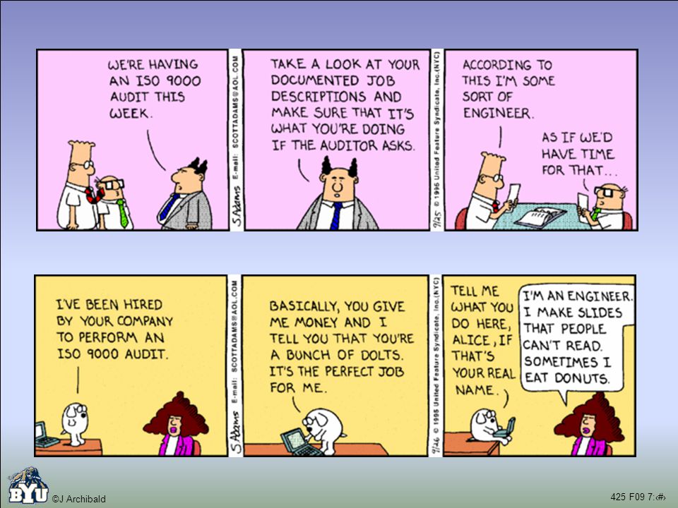


 5/22/20151Dr Alain Beaulieu.>")


2 Scenario Customer: “We would like the word processor to check the spelling of what is typed in. We.>")


