Download presentation
Presentation is loading. Please wait.

4
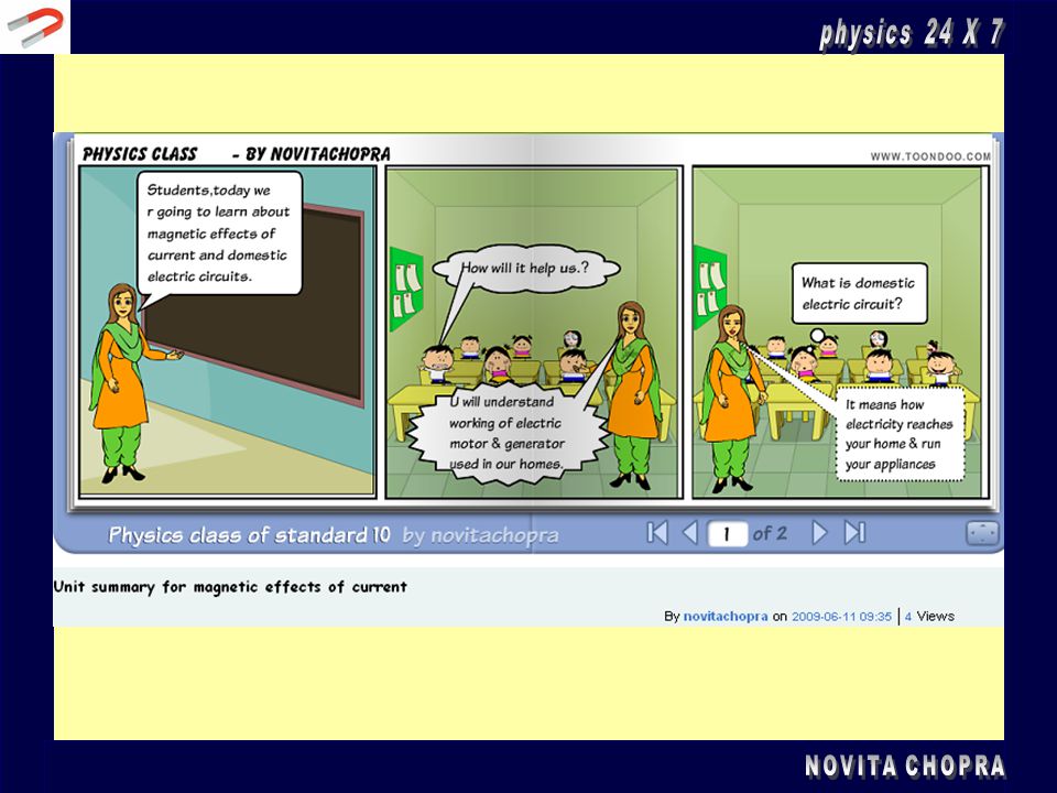
MAGNETIC EFFECTS OF CURRENT

5
Magnetic Field due to Current through Circular loop
Fig shows magnetic field pattern due to circular loop carrying current. Just like a straight conductor, concentric circles representing magnetic field around circular loop become larger and larger as we move away from the wire. By the time we reach at the centre of the circular loop, the arcs of these big circles would appear as straight lines. Right-hand thumb rule can be used to find direction of the field.

6
SOLENOID A solenoid is a long coil made up of a numbers of turns of wire. Magnetic Field Pattern This figure illustrates the field pattern produced by a solenoid when current pass through it. The field lines in the solenoid are close to each other, showing that the magnetic field is stronger inside the solenoid. We can also see that the field lines are parallel inside the solenoid. This shows that the strength of the magnetic filed is about uniform inside the solenoid. The magnetic field of a solenoid resembles that of the long bar magnet, and it behaves as if it has a North Pole at one end and a South Pole at the other.

7
Determining the Pole of the Magnetic Field
The pole of the magnetic field of a solenoid can be determined by the Right Hand Grip Rule. Imagine your right-hand gripping the coil of the solenoid such that your fingers point the same way as the current. Your thumb then points in the direction of the field. Since the magnetic field line is always coming out from the North Pole, therefore the thumb points towards the North Pole.

8
Alternate Method Try to visualise that you are viewing the solenoid from the 2 ends as illustrated in figure (c) below. The end will be a North pole if the current is flowing in the anticlockwise, or a South pole if the current is flowing in the clockwise direction. The strength of the magnetic field can be increased by Increasing the current, Increasing the number of turns per unit length of the solenoid Using a soft-iron core within the solenoid.
 below. The end will be a North pole if the current is flowing in the anticlockwise, or a South pole if the current is flowing in the clockwise direction. The strength of the magnetic field can be increased by. Increasing the current, Increasing the number of turns per unit length of the solenoid. Using a soft-iron core within the solenoid.")
9
Comparative Study of field patterns
Magnetic field lines of a permanent magnet, cylindrical coil, iron-core electromagnet, straight current-carrying wire, and a circular current carrying loop.

10
Force on a current- carrying conductor in a magnetic field
Oersted's experiment shows that a current carrying wire exerts a force on a magnetic needle and deflects it from its usual north-south position. The reverse must also be true, which was proved by the French scientist Andre Marie Ampere, who suggested that a magnet must also exert an equal and opposite force on the current carrying conductor. Conclusion - current carrying conductor experiences a force when placed in a magnetic field. The direction of force is reversed when the direction of current in the conductor is reversed. The force acting on the current-carrying conductor can be changed by changing the direction of the magnetic field.

11
Fleming Left Hand Rule Fleming's left Hand Rule helps us to predict the movement of a current carrying conductor placed in a magnetic field. FORCE According to this rule, extend the thumb, forefinger, and the middle finger of the left hand in such a way that all the three are mutually perpendicular to each another. If the forefinger points in the direction of the magnetic field and the middle finger in the direction of the current, then, the thumb points in the direction of the force exerted on the conductor. Devices that use current carrying conductors and magnetic fields include electric motors, generators, loudspeakers and microphones. MAGNETIC FIELD CURRENT

12
ELECTRIC MOTOR An electric motor is a device which converts electrical energy into mechanical energy. A common motor works on direct current. So, it is also called DC motor. Principle - When a rectangular coil carrying current is placed in a magnetic field, a torque acts on the coil which rotates it continuously. When the coil rotates, the shaft attached to it also rotates and thus it is able to do mechanical work. Parts of a DC Motor are Armature - A D.C. motor consists of a rectangular coil made of insulated copper wire wound on a soft iron core. This coil wound on the soft iron core forms the armature. The coil is mounted on an axle and is placed between the cylindrical concave poles of a magnet.

13
Commutator - A commutator is used to reverse the direction of flow of current. Commutator is a copper ring split into two parts C1 and C2. The split rings are insulated form each other and mounted on the axle of the motor. The two ends of the coil are soldered to these rings. They rotate along with the coil. Commutator rings are connected to a battery. The wires from the battery are not connected to the rings but to the brushes which are in contact with the rings Brushes - Two small strips of carbon, known as brushes press slightly against the two split rings, and the split rings rotate between the brushes. The carbon brushes are connected to a D.C. source.

14
Working of a DC Motor When the coil is powered, a magnetic field is generated around the armature. The left side of the armature is pushed away from the left magnet and drawn towards the right, causing rotation. When the coil turns through 90deg, the brushes lose contact with the commutator and the current stops flowing through the coil.However the coil keeps turning because of its own momentum. Now when the coil turns through 1800, the sides get interchanged. As a result the commutator ring C1 is now in contact with brush B2 and commutator ring C2 is in contact with brush B1. Therefore, the current continues to flow in the same direction.

15
ELECTRIC GENERATOR The electric generator converts mechanical energy into electrical energy. The two types of generators are DC and AC generators: DC Generators - A cycle dynamo and a car dynamo are examples of DC generators. They produce DC AC Generators - AC Generators or alternators are used in power stations and industries to produce AC. Principle ;When a straight conductor is moved rapidly in a magnetic field, then a current is induced in the conductor. It is based on the phenomenon of electromagnetic induction. Construction Main Parts of the AC Generator An AC generator consists of a magnet with concave cylindrical poles, an armature, and a current collecting arrangement. The current collecting arrangement consists of slip rings and brushes.

16
Armature is a soft iron core on which a coil having a large number of turns of insulated copper wire is wound. Magnetic poles are concave and cylindrical. The concave poles produce a radial magnetic field. The ends of the armature are connected to two slip rings. They rotate along with the coil. The slip rings are made of metal and are insulated from each other. There are two brushes B1 and B2 made of carbon. One end of each brush is in contact with the rotating slip rings and the other end is connected to an external circuit. Here the brushes are connected to a galvanometer and brushes do not rotate with the coil. The axle is rotated mechanically from outside by a diesel engine, flowing water, steam or high-speed wind.

17
Working As the armature rotates about an axis perpendicular to the magnetic field, it keeps on changing its relative orientation with respect to the field Thus the flux keeps on changing continuously with time.This change in magnetic flux induces an emf. If the outer terminals of the armature are connected to an external circuit, an electric current flows through it The deflection of the galvanometer needle indicates that an emf is induced The direction of the induced emf is reversed after every half rotation of the coil. Thus in one rotation of the coil, the current changes its direction twice Such a current which changes its direction after equal intervals of time is called alternating current (AC).
.")
18
To get a direct current (DC) generator a split-ring type commutator must be used. In this arrangement, one brush is at all times in contact with the arm moving up in the field while the other is in contact with the arm moving down. Thus a unidirectional current is produced in such a generator. The AC current produced in India has a frequency of 50 hertz (Hz). The coil is rotated at the rate of 50 revolutions in 1 second. So in 50 revolutions the current changes its direction 100 times in one second.
. The coil is rotated at the rate of 50 revolutions in 1 second. So in 50 revolutions the current changes its direction 100 times in one second.")
19
Typical Transmission Line
Electric power is usually generated at places which are far away from the places where it is consumed. At the generating station, the electric power is generated at 11,000 volts. This voltage alternates at a frequency of 50 Hz. The power is transmitted over long distances at high voltage to minimise the loss of energy in the transmission.

20
Domestic Wiring The electric power line enters our house through three wires- namely the live wire, the neutral wire and the earth wire. To avoid confusion we follow a colour code for insulating these wires. The red wire is the live wire, and the black wire is neutral. The earth wire is given green plastic insulation. The live wire has a high potential of 220 volts whereas the neutral wire has zero potential. Thus the potential difference between the live wire and the neutral wire is = 220 volts. The earth wire is much thicker in size and is made of copper. One end of it is connected to a copper plate buried deep under the earth. The earth connection is made to the electric meter and then to the main switch. In our homes, we receive supply of electric power through a main supply (mains), either supported through overhead electric poles or by underground cables.
, either supported through overhead electric poles or by underground cables.")
21
The live wire and neutral wire, coming from the electric pole, enter a box fitted just outside our house which has a main fuse F1. The fuse is connected in series with the live wire. This is done so because it is only the live wire which has a high potential of 220 volts unlike the neutral wire which carries zero potential. The fuse F1 has a high rating of about 50 amperes. Thus it prevents any damage such as fire to the entire electrical wiring entering the house due to short-circuit or overloading. The two wires then enter the electricity meter which records the electrical power consumed by us in kilowatt-hour (kWh). This meter is installed by the electric supply Department of our city. These two wires coming out of the meter are then connected to a main switch which is placed in a distribution box. Another fuse F2 is placed in series with the live wire in this box for the sake of consumer safety.
. This meter is installed by the electric supply Department of our city. These two wires coming out of the meter are then connected to a main switch which is placed in a distribution box. Another fuse F2 is placed in series with the live wire in this box for the sake of consumer safety..")
22
The ditribution circuits are always connected in parallel combination
The ditribution circuits are always connected in parallel combination. In a parallel circuit even if there is a fault or short-circuiting in any one line, the corresponding fuse blows off leaving the other circuits and appliances intact and prevents damage to the entire house. In case short-circuit occurs in the power circuit, then the power-fuse will blow off but our lights will continue to burn as the lighting circuit remains unaffected. A constant voltage of the main line is available for all other electrical appliances. Along with the two wires, a third wire called the earth wire also enters our house as shown in the fig. The earth connection is first made to the electric meter and then to the main switch. This wire then goes into the rooms along with the live and neutral wires

23
YOUR ACTIVITY Visit to further understand the concepts of Lenz Law and ac generator through Java applets and complete the assignment titled “Magnetic Effects of Current”. Visit to learn making of simplest electric dc motor and generator through videos and submit a working model of dc motor under your physics project. Make ppt/brochure/handouts to illustrate the daily life impact of magnetic effects of current and use of electric motors and generators in domestic affairs Study the electrical circuit of your house {under parental supervision}, collect data, draw circuit diagrams and make a presentation on precautions and safety measures to be taken in domestic electrical circuits and appliances to avoid overloading and shock. Research work – visit a hospital / pathology lab or take a virtual tour on the net and talk to experts to study Magnetic Resonance Imaging {MRI}. Investigate further how magnetism can be used in medicine

24
ASSIGHNMENT

26
Assignment The diagram shows the apparatus set-up to investigate the factors affect the strength of an electromagnet. When the switch is closed, the pin are attracted to the soft iron rod. The number of pins attracted to the soft iron rod can be increased by A Increasing the current in the circuit B Increasing the resistance in the rheostat C Deceasing the number of turns in the solenoid D Replacing the battery with alternating current.

27
THANK YOU

Similar presentations