Download presentation
Presentation is loading. Please wait.

1
THERMAL ANALYSIS OF SHELL AND TUBE HEAT EXCHANGER
Prepared By: Guided By: Khalasi Bharat K. Dr. Prabhakaran Sir

2
Contents: HEAT EXCHANGER Types Of Heat Exchangers
Shell-and-Tube Heat Exchangers Thermal Analysis Example References

3
HEAT EXCHANGER: A heat exchanger is a device that is used to transfer thermal energy between two or more fluids, a solid surface and a fluid, solid particulates and a fluid Typical applications involve heating or cooling of a fluid stream of concern and evaporation or condensation of single- or multicomponent fluid streams.

4
Types Of Heat Exchangers
Double-pipe heat exchanger Shell and tube heat exchanger Plate and frame heat exchanger Spiral heat exchanger Pipe coil exchanger Air-cooled heat exchangers

5
Heat Exchanger Types Concentric-Tube Heat Exchangers Parallel Flow
Counterflow

6
Unfinned-One Fluid Mixed
Cross-flow Heat Exchangers Finned-Both Fluids Unmixed Unfinned-One Fluid Mixed the Other Unmixed

7
Compact Heat Exchangers
Achieve large heat rates per unit volume Large heat transfer surface areas per unit volume, small flow passages, and laminar flow.

8
Shell and Tube Heat Exchangers
The shell and tube heat exchanger is the most common style found in industry. As the tube-side flow enters the exchanger, flow is directed into tubes that run parallel to each other. these tubes run through a shell that has a fluid passing through it. Heat energy is transferred through the tube wall into the cooler fluid. Heat transfer occurs primarily through conduction and convection.

9
Shell-and-Tube Heat Exchangers:
One Shell Pass and One Tube Pass Baffles are used to establish a cross-flow and to induce turbulent mixing of the shell-side fluid. One Shell Pass, Two Tube Passes Two Shell Passes, Four Tube Passes

10
Main Parts: 1.Connections 2.Tube Sheets 3.Gaskets 4.Head 5.Mounting
6.Baffles 7. Shell 8.Tube bundle

11
The Thermal Analysis: The fundamental equations for heat transfer across a surface are given by: Q = U A ΔTlm = w Cp(t) (t2 − t1) = W Cp(s) (T1 − T2) or W L Where Q = heat transferred per unit time (kJ/h, Btu/h) U = the overall heat transfer coefficient (kJ/h-m2 oC, Btu/hft2-ºF) A = heat-transfer area (m2, ft2) Δtlm = log mean temperature difference (oC, ºF) Cp(t) = liquid specific heat tube side, Cp(s) = liquid specific heat shell side (kJ/kg-ºK, Btu/lb-ºF) w = tube side flow W = shell side flow (kg/h, lb/h) The log mean temperature difference ΔTlm (LMTD) for counter current flow is given by:
 (t2 − t1) = W Cp(s) (T1 − T2) or W L. Where Q = heat transferred per unit time (kJ/h, Btu/h) U = the overall heat transfer coefficient (kJ/h-m2 oC, Btu/hft2-ºF) A = heat-transfer area (m2, ft2) Δtlm = log mean temperature difference (oC, ºF) Cp(t) = liquid specific heat tube side, Cp(s) = liquid specific heat shell side (kJ/kg-ºK, Btu/lb-ºF) w = tube side flow. W = shell side flow (kg/h, lb/h) The log mean temperature difference ΔTlm (LMTD) for counter current flow is given by:")
12
A correction factor is applied to the LMTD to allow for the departure from true counter current flow to determine the true temperature difference. ΔTm = Ft ΔTlm The correction factor is a function of the fluid temperatures and the number of tube and shell passes and Correlated as a function of two dimensionless temperature ratios

13
The correction factor Ft for a 1-2 heat exchanger which has 1 shell pass and 2 or more even number of tube passes is given by: The overall heat transfer coefficient U is the sum of several individual resistances as follows: The combined fouling coefficient hf can be defined as follows:

14
Area of Flow: Spacing Required:
Shell side cross flow area aS is given by Spacing Required: Spacing does not normally exceed the shell diameter Maximum spacing is given by:

15
Shell side Film Coefficient Methods for Single Component Condensation in Laminar Flow:
Horizontal condenser sub coolers are less adaptable to rigorous calculation But give considerably higher overall clean coefficients than vertical condenser sub coolers which have the advantage of well defined zones. The Nusselt Method: The mean heat transfer coefficient for horizontal condensation outside a single tube is given by the relationship developed by Nusselt. This correlation takes no account of the influence of vapour flow which, in addition to the effect of vapour shear, acts to redistribute the condensate liquid within a tube bundle.

16
The Kern Method: Kern adapted the Nusselt equation to allow evaluation of fluid conditions at the film temperature For horizontal tube surfaces from 0° to 180° the above equation can be further developed to give

17
McAdam extended the Kern equation to allow for condensate film and splashing affects.
The loading per tube is taken to be inversely proportional to the number tubes to the power of This equation requires the film to be in streamline flow Reynolds Numbers in range 1800 to 2100

18
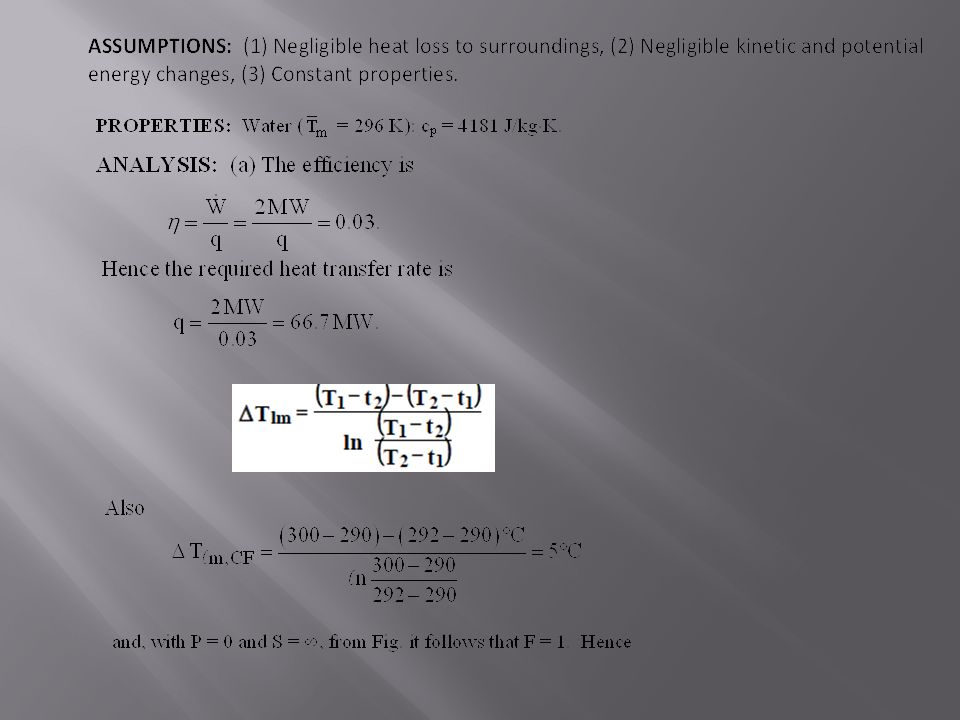
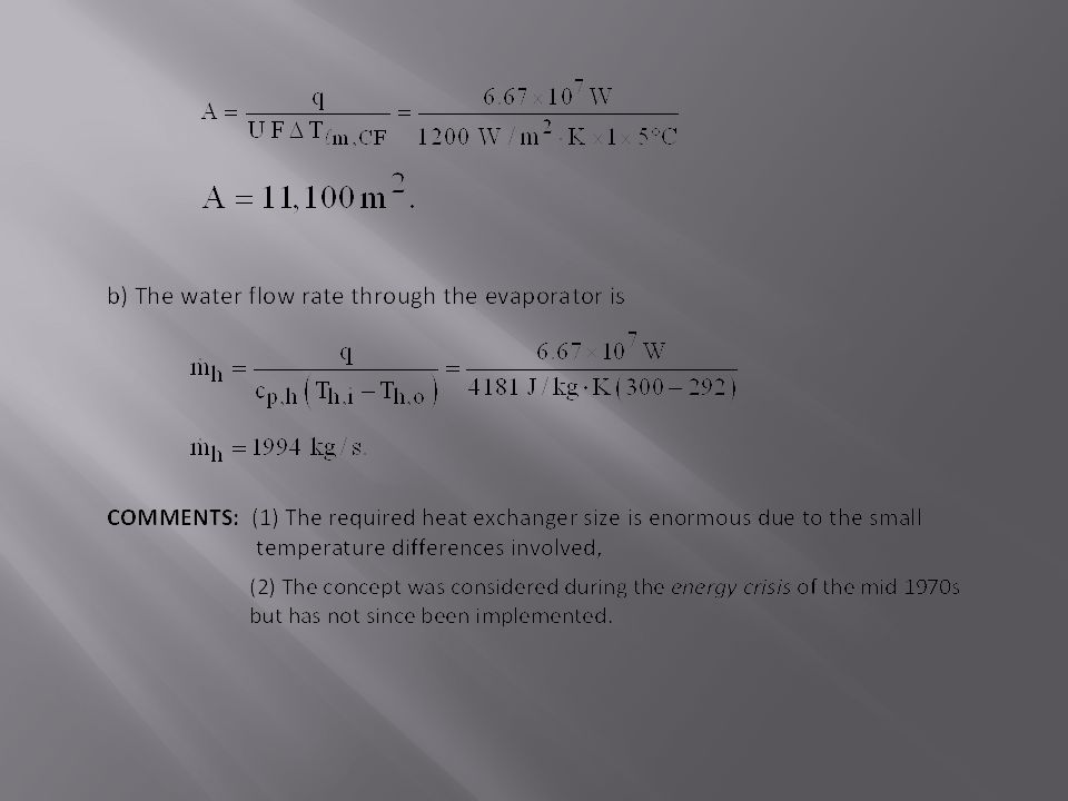
Example: Problem : Design of a two-pass, shell-and-tube heat exchanger to supply vapour for the turbine of an ocean thermal energy conversion system based on a standard (Rankine) power cycle. The power cycle is to generate 2 MW at an efficiency of 3%. Ocean water enters the tubes of the exchanger at 300K, and its desired outlet temperature is 292K. The working fluid of the power cycle is evaporated in the tubes of the exchanger at its phase change temperature of 290K, and the overall heat transfer coefficient is known.
 power cycle. The power cycle is to generate 2 MW at an efficiency of 3%. Ocean water enters the tubes of the exchanger at 300K, and its desired outlet temperature is 292K. The working fluid of the power cycle is evaporated in the tubes of the exchanger at its phase change temperature of 290K, and the overall heat transfer coefficient is known.")
21
REFERANCES: Design And Rating Shell And Tube Heat Exchangers , By John E. Edwards Engineering Data Book, By Professor John R. Thome en.wikipedia.org

22
THANK YOU

23
Any Question ?

Similar presentations


>")


