Download presentation
Presentation is loading. Please wait.

1
SELECTION OF SUPPORTING ARRANGEMENT FOR CRITICAL PIPING By DILEEP PILLAI

2
PURPOSE OF STRESS ANALYSIS The selection of supporting arrangement is based on Piping Stress analysis. Piping Stress Analysis is carried out to - 1. Keep STRESSES in the piping within its allowable values. 2. Keep REACTIONS due to the piping on equipment nozzles within their allowable values. 3. Provide SUITABLE SUPPORTS to take the DEAD WEIGHT of the piping while providing free movement of the piping system.

3
PROCEDURE Static analysis – This consists of first a free Thermal Run and a Weight distribution Run.followed by Hanger Selection. After that the final Thermal Run with selected hanger and all restraints in place is taken. The hangers are selected based on the thermal movements and the the pipe weight. Analysis is done in such a way that the reactions at the terminals are kept within their allowable values. Restraints are used to help achieve this as well restrict undue pipe movements. Hangers are selected with margin in movement on both top and bottom. In all KWU sets the analysis is done in such a way so that no pipe weight is transferred to the turbine and valve nozzles. To ensure this as well as to take care of the actual pipe weight (due to pipe tolerances) with respect to the theoretical weights the piping is floated on unlocked spring hangers before connecting to turbine nozzles during erection.
 with respect to the theoretical weights the piping is floated on unlocked spring hangers before connecting to turbine nozzles during erection..")
4
The various static analysis outputs generated by us are- Piping stress check as per codes Hanger and support tables Forces and moments table consisting of - –Weight –Hot ( immediate Hot) –Hot (safety valves blowing) –Cold Relaxed –Cold Relaxed (with upper casing removed, in case of split casing) The analysis is done up to the Turbine CG so as to facilitate stability calculations. The reactions at the turbine are limited by two criterion, the turbine stability and the nozzle strength.

5
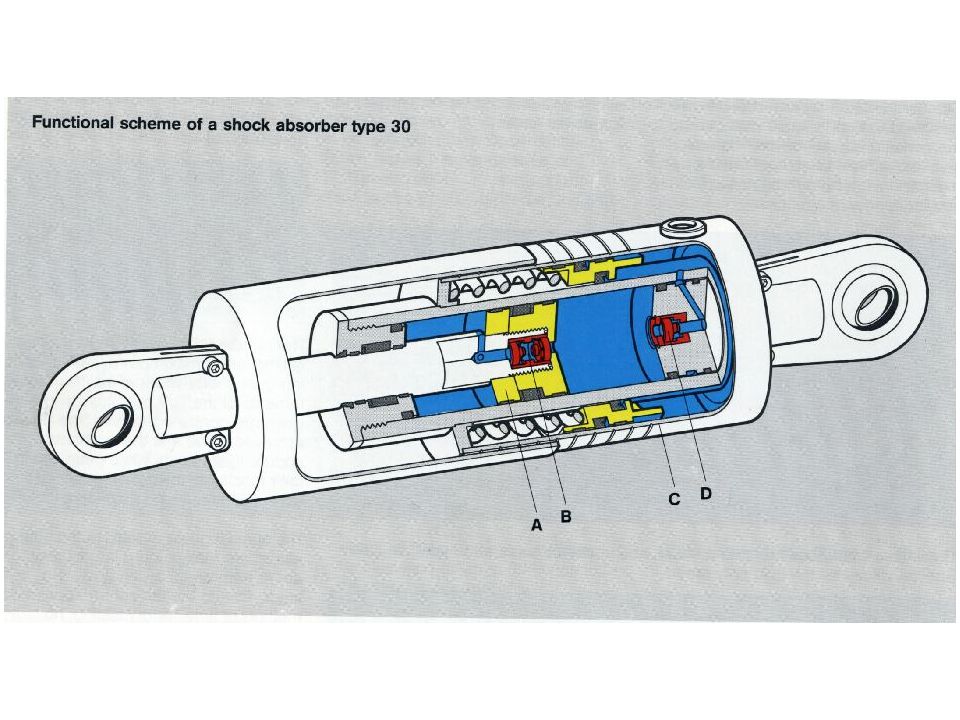
Dynamic analysis – We carry out a Dynamic Analysis of MS, HRH and CRH piping because of quick closing of ESV & CV in MS piping and IV & CV in HRH piping. A pressure shock wave is generated in the piping when the valve closes fast which travels at the speed of sound in the piping. Depending on the actual valve closing time, the mass flow through the valves and the piping lengths the forcing functions are worked out in each leg. With these forcing functions a vibration analysis of the piping is carried out. Wherever found necessary shock absorbers are introduced to the piping system so as not to disturb the static analysis as well as satisfy dynamic requirements. The analysis gives us the stresses in the piping, forces and moments at the equipments and restraints and the deflection of the piping at various points. The hangers are then once again checked to determine whether the earlier margins provided during static analysis were adequate. They should not top out or bottom out during dynamic conditions also. The restraints are finally designer to cater for static + dynamic loads. The additional reactions at equipment nozzles due to dynamic conditions are also taken into consideration

6
Stresses 1.Primary stresses 2.Secondary stresses

7
PRIMARY STRESSES Primary stresses are those stresses caused by load that act continuously. They are not self limiting and if yield stress is reached yielding will occur. Primary stresses for which the piping is usually analyzed are Dead weight Pressure Occasional loadings such as earthquake and steam hammer (earthquake in case the plant is located in an earthquake prone area)
.")
8
SECONDARY STRESSES Secondary stresses are stresses which are self limiting and failure occurs by repeated application. Thermal stresses are secondary stresses and failure occurs through repeated cycles and subsequent fatigue.

9
Stress comparison as per code ANSI B31.1 Longitudinal Stresses due to Sustained Loads Sp + Sw <= Sh Longitudinal Stress due to Occasional Loads Sp + Sw + So <= kSh, k= 1.15 for duration < 10 % of op. time k= 1.20 for duration < 1 % of op. time Thermal Expansion Stress Range Se <= Sa Sa = Allowable Stress Range = f (1.25 Sc +0.25 Sh) Sustained + Thermal Expansion Stress Sp + Sw + Se <= (Sh +Sa)
 Sustained + Thermal Expansion Stress Sp + Sw + Se <= (Sh +Sa).")
10
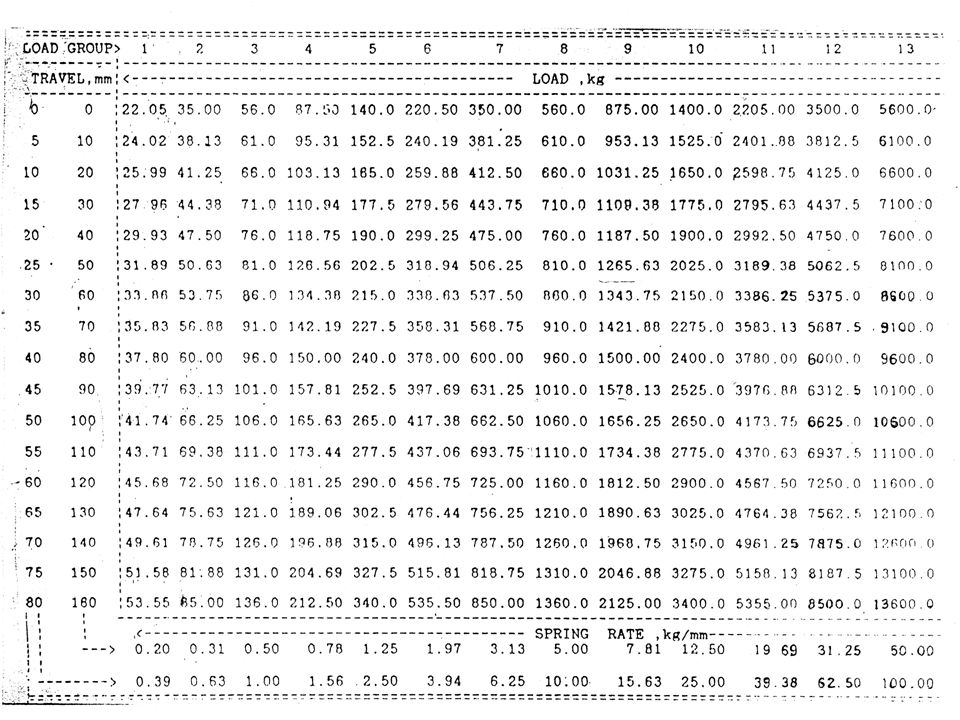
HANGER SELECTION Hanger selections are made based on static analysis, and then finally checked for dynamic deflections as well. Variable springs are usually selected for deflections of up to 40 mm. Beyond 40 mm Constant Load hangers are selected. Variability of load for variable load hangers are usually kept within 25%. In Constant load hangers the variability is theoretically zero. Hanger Loads consists of pipe wt, media wt, insulation wt and wt of hanger components such clamps,channels,tie rods etc. Variable Load hangers are selected from ‘Load Tables’ given in the Hanger catalogue by Piping Center. While selecting springs, care is taken to see that top and bottom margins are available in all operating conditions such as Cold, Hot and Cold Relaxed. Care is also taken to see that dynamic deflections are within the top and bottom margins provided.

11
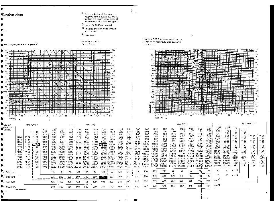
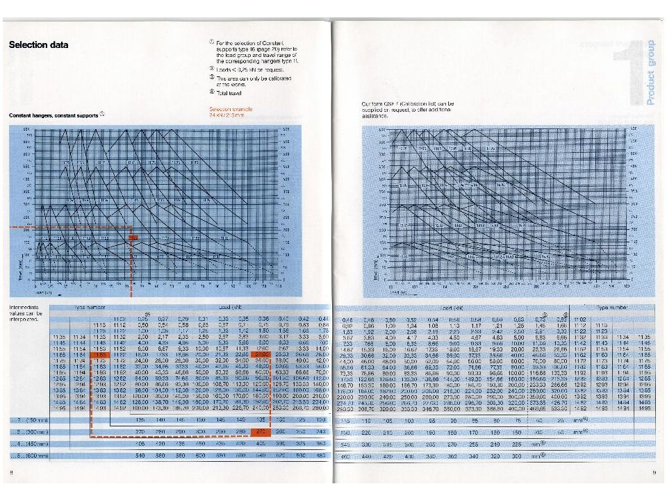
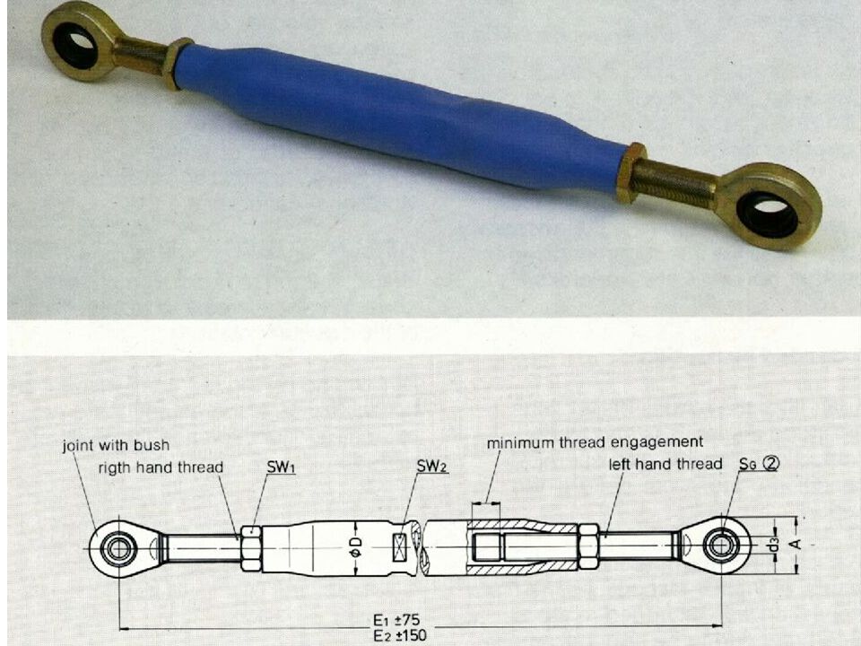
Constant Load hangers are selected using ‘Selection data’ charts of PC. Here margins are checked for Cold and Hot conditions and also for dynamic movements. Rigid supports are provided judiciously in the system making the system as rigid as possible while still keeping stresses in the piping as well as reactions at the terminal points within limits. Rigid supports may be tie rod hangers, struts or restraints made of pipe attachments. Shock Absorbers are only used when it becomes absolutely necessary, to absorb the pressure shock wave generated due to quick closing of ESV & CV and IV & CV. The loads are decided based on Dynamic Analysis results

Similar presentations


 Energy The amount of energy in an object depends on: 1.Mass of the object 2.Temperature of the object 3.The nature of.>")


 Philadelphia University Faculty of Engineering>")


>")

