Download presentation
Presentation is loading. Please wait.

1
Computer technology in America’s Cup Yacht Racing
Dr. J. Craig Mudge Pacific Challenge ee380 Colloquium Computer Systems Laboratory Stanford University Feb 19, 2003 Goal: present how computer technology is used in the various aspects of an America’s Cup campaign – including the design of the sleek racing yachts, the evaluation of alternate designs, campaign management, and computer help during a race. This week, New Zealand is defending the America's Cup, the longest-running sports competition in the world, against a challenger selected from nine syndicates by a series of two-boat elimination races beginning in October 2002. The would-be challengers came from syndicates based in France, Great Britain, Italy, Sweden, Switzerland, and the United States. Some syndicates have spent $80 million on their campaigns. Alinghi, the Swiss challenger won the right to challenge for the Cup. Before we look at some video footage of the racing in the last week off Auckland in NZ, let’s look at the race course

2
Big deal for the economy of the defending nation. Perhaps $300 m in NZ.

3
6 legs in America’s Cup course
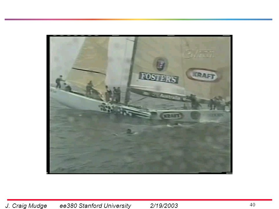
Alinghi Race 2:- Time Min:sec Delta in seconds Start 1 26:11 12 2 24:14 -34 3 26:37 -26 4 22:43 -14 5 27:33 finish 25:43 7 Now look at a photo taken at the mark at the top of this diagram.

4
How a sailboat moves ahead
Downwind Push on sails Upwind Lift from sails Lift from keel Context Changes in wind strength and direction Changes in wave shape, direction, and frequency The boat on the left has just gone around the floating mark, and the boat on the right is trailing and is about to go around the mark. <- Notice the angle of heel is quite different upwind to downwind. These changes from day to day, and from minute to minute in some cases, add to the complexity of the design and modeling. This weekend, Race 2 was sailed in 10 Knots (approx 10 miles per hour), whereas Race 3 was sailed in winds around 17 knots. Race 1 had extensive little waves of about 18 inches high (?) Acknowledge corner of white spinnaker
, whereas Race 3 was sailed in winds around 17 knots. Race 1 had extensive little waves of about 18 inches high ( ) Acknowledge corner of white spinnaker.")
5
Defender vs Challenger
Video clips of last couple of days racing - what to watch for Now turn to some video, and I’ll use this still image to point out some things to look for Helmsman steering with one of two linked wheels. Steering is with a rudder the way the movable part of the tail provides steering on an aircraft Tactician looking at his computer display Orange line (we never use the word rope) is led from the corner of the forward of the two sails to a winch drum controlled by the Jib trimmer Similarly the yellow line controlled by the Mainsail trimmer each winch drum is coupled to crank handles powered by the arms of the two grinders working together. Moving to the top image we’ll see two types of sails. When the boat is heeling over, these two sails are closely aligned with the direction of the hull, and the boat is zig-zagging , or beating, up wind. Going in the other direction, namely downwind, the sails are roughly at right angles to the boat, and the pressure on the sails is pushing the boat downwind; at this point also the big white parachute sail is at the front of the boat. So let's roll the video.
 is led from the corner of the forward of the two sails to a winch drum controlled by the Jib trimmer. Similarly the yellow line controlled by the Mainsail trimmer. each winch drum is coupled to crank handles powered by the arms of the two grinders working together. Moving to the top image we’ll see two types of sails. When the boat is heeling over, these two sails are closely aligned with the direction of the hull, and the boat is zig-zagging , or beating, up wind. Going in the other direction, namely downwind, the sails are roughly at right angles to the boat, and the pressure on the sails is pushing the boat downwind; at this point also the big white parachute sail is at the front of the boat. So let s roll the video.")
7
Elementary theory Lift drag Lift drag (or resistance)
Aerodynamic forces from sails Leeway angle hydrodynamic There are two types of forces, each generated by a fluid moving past a curved surface aero and hydro. For the keel to provide lift we need a non-zero angle of attack – this leeway angle is approx 5 degrees Lift drag Lift drag (or resistance)
")
8
Tacking up wind Zig-zagging up wind towards our destination
Wind direction Zig-zagging up wind towards our destination The boat that sails at an angle “closer to the wind” gets upwind faster Now look at moving up wind again. <- Obviously the designer of the sails and the hull tries to make the boat sail efficiently at the smallest angle to the wind.

9
Polar representations of boat speed
Radial representation of Boat speed at different true wind angles for one windspeed 5 We represent the upwind and downwind boatspeeds, and points in between, as follows. <- Upwind it’s an airplane wing – generating lift Downwind its both a parachute and lift Its at this point that boats with very low resistance, such as ice boats, can sail faster than the wind. Another type of boat with low resistance is a catamaran – two narrow floats. Stan Honey, navigator on the catamaran Playstation 2 in likes to say it this way: the boat was fast enough s.t. if released a He balloon, the boat would pass in front of it. SO how do we use these polars? Given a wind speed, they show the crew what angle is best to sail at, and what the speed should be. 10 20 (Adapted from 12 metre designed by S Killing)
")
10
A list of computer uses Area Type Design of hull
Hydrodynamic modeling (to reduce drag) Hull appendages Hydrodynamic modeling (lift and drag) Design of sails Aerodynamic modeling; photogrammatic Computational Fluid Dynamics (CFD) Modeling, analysis, and visualization – sails, hulls, appendages Two boat testing Data collection and data management Navigation/tactics/ strategy Performance parameters; predictions for next leg Campaign Project/financial management, travel, web site Weather Forecast wind patterns for each race Sports media Visualization of race course from telemetry Let me complete this introductory section by acknowledging some colleagues
 Hull appendages. Hydrodynamic modeling (lift and drag) Design of sails. Aerodynamic modeling; photogrammatic. Computational Fluid Dynamics (CFD) Modeling, analysis, and visualization – sails, hulls, appendages. Two boat testing. Data collection and data management. Navigation/tactics/ strategy. Performance parameters; predictions for next leg. Campaign. Project/financial management, travel, web site. Weather. Forecast wind patterns for each race. Sports media. Visualization of race course from telemetry. Let me complete this introductory section by acknowledging some colleagues.")
11
Acknowledgements Jim Antrim, naval architect
Richard Burton, sailor and computer scientist Margot Gerritsen, Computational Fluid Dynamics (CFD) specialist, Stanford Yacht Research Stan Honey, record-breaking navigator Olivier Le Diouris, sailor and software engineer Eric Steinberg, electronics on America True Brian Tramontana, PARC multimedia * ESPN for video clips * americascup.yahoo.com for photos * Virtual Spectator for screenshots of race course
 specialist, Stanford Yacht Research. Stan Honey, record-breaking navigator. Olivier Le Diouris, sailor and software engineer. Eric Steinberg, electronics on America True. Brian Tramontana, PARC multimedia. * ESPN for video clips. * americascup.yahoo.com for photos. * Virtual Spectator for screenshots of race course.")
12
- both canoe body and appendages
Outline Hull design - both canoe body and appendages Sail design Materials - hull and sails Two-boat tuning Winning races Designers break the floating piece into two parts. Let’s return to our force diagram, showing both the aerodynamic forces from the sails, - and the hydrodynamic forces from the keel.

13
Adding heeling/righting moments to two forces
Aerodynamic forces from sails Hydro- mechanical Righting moment Leeway angle hydrodynamic Aerodynamic Heeling moment Here we add the third force due to heeling, shown in green. The hull shape provides space for its payload, is shaped to give low wetted surface area, and has strength to hold the appendages underneath and the rig above. Also the hull has to withstand expected sea conditions. PAUSE Moreover, by adding the moments as the third force, we have the three balance equations involved in an equilibrium sailing condition And the solving of these 3 is the basis of modeling by the designer. Heeling Righting Lift Drag Lift Drag (or resistance)
")
14
Lateral stability Heeling moment from sails
Left hand boat is wide to give form stability The boat on the right is more like a Cylinder - biggest evolution since IACC started – use only ballast for stability. Extreme ballast from bulb (20 tons of a 24 ton IACC boat) Lead ballast is placed in the lower portion of the keel.
 Lead ballast is placed in the lower portion of the keel.")
15
Alternative to lead bulb for righting moment
Even though it’s not contributing to righting, the keel (centerboard) is there to prevent sideways slipping and to generate lift Hull length = 18 Sandbaggers, an influential American design in the late 1800s Water ballast is current genre in fast ocean racing yachts. Sydney Harbour 18 ft skiffs
 is there to prevent sideways slipping and to generate lift. Hull length = 18. Sandbaggers, an influential American design in the late 1800s. Water ballast is current genre in fast ocean racing yachts. Sydney Harbour 18 ft skiffs.")
16
More 18 ft skiffs from Sydney
A very influential design - on modern racing yachts - on latest Olympic class (49er) Yendys 1924 Anecdote: Sydney Harbour racing: as wind drops, crew swim ashore one-by-one, as requested by the captain
 Yendys Anecdote: Sydney Harbour racing: as wind drops, crew swim ashore one-by-one, as requested by the captain.")
17
Newer IACC boats are much narrower
Having looked at sideways stability, lets look at the drag on the hull as it moves through the water.

18
Resistance components - upwind
heeled Added waves Induced (from leeway) Heel (extra viscous+wave) upright Wave (pushing the water) Viscous (friction from wetted surface) [describe each one] Induced -- as water flows form higher pressure (leeward side) to lower pressure and causing eddies. An important take away from this talk is shown in this diagram- Each of these components has to be modeled (using empirical data or approximations of theoretical representations of fluid flow). Then assumptions are made for how the components interact (Fig 5.4, Larsson, 2000)
 Heel. (extra viscous+wave) upright. Wave. (pushing the water) Viscous. (friction from. wetted surface) [describe each one] Induced -- as water flows form higher pressure (leeward side) to lower pressure and causing eddies. An important take away from this talk is shown in this diagram- Each of these components has to be modeled (using empirical data or approximations of theoretical representations of fluid flow). Then assumptions are made for how the components interact. (Fig 5.4, Larsson, 2000)")
19
Appendages: side force and resistance
Side force (also called Lift) From both keel and rudder Lift/drag tradeoff Aspect ratio Bulb shape Turbulence Here we draw on classical wing theory. The aspect ratio is the most important parameter for the lift and drag. This ratio refers to how tall an object is relative to its width. Ideally we want more depth (or long wings in case of airplane) to give a high aspect ratio but there are limits – on an airplane wing structural or airport rules - in a boat, the rule, or desire to sail in shallower waters CLICK Winglets Now look at the computer visualization of flow of water passed a bulb on a keel with winglets Tip vortices if depth is limited End wall not practical, so Winglets used Winglets also provide lift when boat heeled
 From both keel and rudder. Lift/drag tradeoff. Aspect ratio. Bulb shape. Turbulence. Here we draw on classical wing theory. The aspect ratio is the most important parameter for the lift and drag. This ratio refers to how tall an object is relative to its width. Ideally we want more depth (or long wings in case of airplane) to give a high aspect ratio but there are limits – on an airplane wing structural or airport rules. - in a boat, the rule, or desire to sail in shallower waters. CLICK. Winglets. Now look at the computer visualization of flow of water passed a bulb on a keel with winglets. Tip vortices if depth is limited. End wall not practical, so Winglets used. Winglets also provide lift when boat heeled.")
20
Surface pressure and Streamlines around bulb
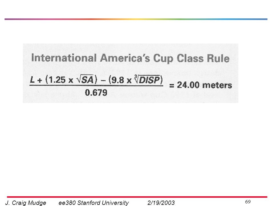
Just one plane If showed neighboring planes, one would see interaction between them, which would appear as a spiraling vortex From M Sawley (2002) at Switzerland’s EPFL, in Lausanne, an advisor to Alinghi
 at Switzerland’s EPFL, in Lausanne, an advisor to Alinghi.")
21
An overview of numerical modeling in yacht design
Fundamental tool is a predictor of performance to compare different designs Called a VPP (Velocity Prediction Program) -- since early 70s Given a wind speed and wind angle, a VPP predicts boat speed, heel, and leeway
 -- since early 70s. Given a wind speed and wind angle, a VPP predicts boat speed, heel, and leeway.")
22
Modeling boat speed - VPP
Go quickly across a few (Milgram, 1998)
")
23
An overview of numerical modeling in yacht design
Fundamental tool is a predictor of performance to compare different designs Called a VPP (Velocity Prediction Program) -- since early 70s Given a wind speed and wind angle, a VPP predicts boat speed, heel, and leeway The balance equations are solved Keel lift and side force Sails lift and drag Overturning moment Modeling these forces in the balance equations is (currently) approximate Navier Stokes equations (set of differential equations governing the motion of a fluid) are central part Models are combination of empirically based and approx of N-S equations
 -- since early 70s. Given a wind speed and wind angle, a VPP predicts boat speed, heel, and leeway. The balance equations are solved. Keel lift and side force. Sails lift and drag. Overturning moment. Modeling these forces in the balance equations is (currently) approximate. Navier Stokes equations (set of differential equations governing the motion of a fluid) are central part. Models are combination of empirically based and approx of N-S equations.")
24
Overall Hull Design process
Decide range of wind strength, sea state 2. Coarse exploration of shapes by numerical modeling, incl CFD 3. Then tank testing 4. Then build one real thing 5. Refine with two-boat testing Tank testing very expensive; limited to 2 or 3 models. Ensure large enough model, say 8 metres, to avoid scaling problems In 1983, Australia II with its revolutionary winged keel on the Cup, the first time it had been taken away from America. John Bertrand was the skipper, and I later asked him what was different from previous challenges. … In 2001 there was a America's Cup Jubilee regatta in Cowes and Australia II was there with many other old Cup boats. Hugh Treharne, the tactician on Australia II when she won was of course ther too. Later I asked him what it was like – he said the boat was like an old glove – she fitted so well. This emphasizes the enormous amount of time teh sailor spend on the boat in preparation.

25
An overview of numerical modeling in yacht design …contd.
Computational Fluid Dynamics (CFD) RANS (Reynolds-Averaged Navier-Stokes) is a more computationally tractable form of the N-S equations. In RANS, the flow variables are split into one time-averaged (mean) part, and one turbulent part. The mean values are solved. And the turbulent part is expressed in terms of the mean part. CFD applications Aerospace -- wing sections, airframe shapes, etc Automotive -- flow in air intake, right on through engine Mechanical – pumps Chemical e.g., separators Environmental e.g., water borne pollution Physiological – cardio vascular system
 RANS (Reynolds-Averaged Navier-Stokes) is a more. computationally tractable form of the N-S equations. In RANS, the flow variables are split into. one time-averaged (mean) part, and one turbulent part. The mean values are solved. And the turbulent part is expressed in terms of the mean part. CFD applications. Aerospace -- wing sections, airframe shapes, etc. Automotive -- flow in air intake, right on through engine. Mechanical – pumps. Chemical e.g., separators. Environmental e.g., water borne pollution. Physiological – cardio vascular system.")
26
An overview of numerical modeling in yacht design …contd.
Typical computer resources are these at EPFL, Lausanne SGI Origin 3800 128 MIPS R14000 Pc (500Mhz; 64 GB RAM) Swiss T1 64 DEC Alpha ev6 Pc (500 Mhz; 32GB RAM) Dell Precision 530 2 Pentium Xeon Pc (1.7 GHz, 2GB RAM) Largest RANS simulations: 5 million mesh cells: 10 hours on 16 Pc c.f. AC2000 campaign: 2 million mesh cells: 10 hours on 12 Pc Origin 2000 Transition: so let’s see how it all worked out in the current AC competition
 Swiss T1. 64 DEC Alpha ev6 Pc (500 Mhz; 32GB RAM) Dell Precision Pentium Xeon Pc (1.7 GHz, 2GB RAM) Largest RANS simulations: 5 million mesh cells: 10 hours on 16 Pc. c.f. AC2000 campaign: 2 million mesh cells: 10 hours on 12 Pc Origin Transition: so let’s see how it all worked out in the current AC competition.")
27
Unveiling January 7, 2003 Alinghi Oracle
Cow: Who said Swiss are humorless Alpine horns, although the cynic might suggest that this bout of Swiss nationalism is to counter the criticism of the multinational nature of their crew. In the 16-person crew, there are just two Swiss.

28
Different winglet configurations and bulb shapes
QUICKLY to normalized view

29
Different winglet configurations and bulb shapes
Oracle Alinghi Do they know what they are doing? Jim Antrim’s comment Summary of this section hull design: just how important it is to get the prediction of wind strength right In higher winds, wave drag higher proportion of total drag Tradeoff weight sail shape keel weight PAUSE When I think about the computers I have designed, I think we had a better handle on things – modeling the workload, modeling the physics, a useful set of layers of abstraction, good simulation and verification tools, and so on. However, we had a better handle on things, not because we were smarter than naval architects, but because yacht design is a much harder problem. Team NZ (based on photos at the unveiling 1/7/03)
")
30
Universities working in yacht design
University of Auckland Technical University of Berlin Chalmers University of Technology Kiel University EPFL, Lausanne, Switzerland MIT University of Maryland University of Michigan University of Southampton Stanford Yacht Research Center for Turbulence Research, Stanford Just give the list

31
Outline Sail design Hull design Materials Two-boat tuning
Winning races Again we use classic wing theory Unlike the hull, the camber of the surface can be changed while it’s in operation.

32
Positioning and shaping
Crew positions the sails according to required angle of attack - from polars Sailors shape the sail using control lines attached to the edge of a sail Sailors know how to get a desired shape – with the control lines, so the real issue for a talk like this is what is the right shape? The shape is to provide max lift/drag and to keep the flow laminar, not separated or turbulent.

33
What is the right shape? Sailmaker designs each sail for a range of wind strength and wave type. (Sailor selects a sail from the suite, according to expected conditions.) Want nice laminar flow, without separation and turbulence Lift vs drag curve; polars again Both wind tunnels and CFD used Sail design is challenging. The hull, sails and rig form an integrated system with many parameters that should be optimized simultaneously. However, the fluid-structure interaction between the three-dimensional flow around the sail and the hull, and the effect of the dynamic motion of the boat on the sail flow and hull hydrodynamics are complex.
 Want nice laminar flow, without separation and turbulence. Lift vs drag curve; polars again. Both wind tunnels and CFD used. Sail design is challenging. The hull, sails and rig form an integrated system with many parameters that should be optimized simultaneously. However, the fluid-structure interaction between the three-dimensional flow around the sail and the hull, and the effect of the dynamic motion of the boat on the sail flow and hull hydrodynamics are complex.")
34
Vertical characteristics of wind
Apparent wind is the wind we feel on the boat, as opposed to the true wind. As we go from deck to top of mast, the wind increases in strength and apparent direction 8 7 5 Has implications for both sail designers and sailors (sail trimming)
")
35
Design of downwind sails

36
Wind tunnels in sail design
University of Auckland Twisted Flow Wind Tunnel Sailors spend hours with tunnel. Trimming and trimming to explore different shapes and angles of attack. Note: because trimming upwind sails is much finer, this wind tunnel is not used for upwind sails. In AC2003, only Oracle and TNZ used wind tunnels with twisted flow – Team NZ used this one, and Oracle built their own, very much like this one. Courtesy U Auckland, Seahorse magazine

37
Outline Materials - hull, sails, and rig Hull design Sail design
Two-boat tuning Winning races Changes in materials, e.g., less stretch in sailcloth or stronger lighter materials in hull construction is requiring more extensive computer modeling, buyt I won’t go into this in any detail.

38
Ocean racers have to be stronger
Courtesy Richard Bennett

39
Forces on rig and hull Now in this video of One Australia, please pay attention to the detailed explanation that John Bertrand gives after the sinking.

41
Prominent logo of sponsor

42
OneAustralia 1995

43
Older sail material Courtesy: Mariners’ Museum Desirable chars:
Low stretch Low weight High strength Endurance Resistance to aging in sunlight Courtesy: Mariners’ Museum

44
Materials and shaping Desired 3D shape in CAD model
Flax Cotton Japara silk various polyesters (with or without film) (Kevlar is the best known of the aramid fibers) Carbon Desired 3D shape in CAD model Panel shape Mold shape Sew panels Apply layers (liquid/fiber)
 (Kevlar is the best known of the aramid fibers) Carbon. Desired 3D shape in CAD model. Panel shape Mold shape. Sew panels Apply layers. (liquid/fiber)")
45
Improved sail shape with modern materials
Also note the fat stripes This time it appears that all syndicates used what they called Sil Scanning - photogrammatic techniques

46
Lexcen keel Oracle kite Canting keel
Novel designs Lexcen keel Oracle kite Canting keel

47
Ben Lexcen’s winged keel 1983
Start with the first keel with winglets – America’s Cup 1983. Painted with blue sections to look like a Conventional high-aspect ratio keel with sweep of 30 degrees Lexcen, a genius designer experimented in Holland, starting 1981 for several months with his friend peter van oossanen 24 ft models Upside down keel (to get weight down and beat draft restriction) Added wings to cope with horrendous vortexes Further experiments to get position, overall size, and angle of dihedral I got info from Peter Joubert, prof of, whom I used to meet annually in the 80s .. .and he published a delightful paper in 1986 jointly with van oossanen. Joubert was racing his 43 fter in the bad Hobart. He was 74 and had completed many Hobart races in this boat. It rolled sideways and he received broken ribs when a crew member crashed into him down below.. One crew member was washed overboard and picked up by helicopter 40 mins (?) later. Courtesy: Rosenfeld
 Added wings to cope with horrendous vortexes. Further experiments to get position, overall size, and angle of dihedral. I got info from Peter Joubert, prof of, whom I used to meet annually in the 80s .. .and he published a delightful paper in 1986 jointly with van oossanen. Joubert was racing his 43 fter in the bad Hobart. He was 74 and had completed many Hobart races in this boat. It rolled sideways and he received broken ribs when a crew member crashed into him down below.. One crew member was washed overboard and picked up by helicopter 40 mins ( ) later. Courtesy: Rosenfeld.")
48
Oracle kite Mention kite surfers

49
Canting keel and canard
Wild Oats and Schock 40 Acknowledge Reichel-Puch and Dynayacht From Dynayacht: Is it hard to control the boat with two "rudders"? No. It's so easy, you soon forget you have two steering foils. It steers like a normal sailboat, only better. Both steering foils are controlled by the tiller so steering is intuitive and as simple as any traditional sailboat. The front foil (rudder) turns in an opposite direction to the aft foil (which makes sense since it is forward of the boat's pivot point). Steering control is much more positive than on a boat with a single rudder. MentionSchock 40 (Reichel-Puch, Dynayacht, 2002)
 turns in an opposite direction to the aft foil (which makes sense since it is forward of the boat s pivot point). Steering control is much more positive than on a boat with a single rudder. MentionSchock 40. (Reichel-Puch, Dynayacht, 2002)")
50
Outline Two-boat tuning Hull design Sail design Materials
Winning races

51
Why two-boat tuning Shortcomings of numerical modeling and tank testing Sensors not accurate enough A two boat lead at end of a 3 mile leg requires boat speed 0.7% accuracy; Accuracy on wind direction, strength also difficult hard to get accuracy;

52
Instruments and data logging on J/105 Kookaburra
To motivate this section of the talk, we’;; look quickly at the data logging on my 35 foot racing yacht Data from instruments:- Wind speed (true and apparent); Boat position; Heading; Boat speed (through water and over the ground); Etc etc
; Boat position; Heading; Boat speed (through water and over the ground); Etc etc.")
53
A leg of a race selected for further analysis

54
Log of Wind Oscillations during a race
221º 299º Why wind direction important in a race. Guys up the mast. Importance wind shifts very apparent in finals Oracle vs Alinghi

55
Two-boat tuning – Team NZ
Each boat can see the data from the other boat (wireless links) Range and bearing – laser Normal instruments plus rudder angle deflection sensors on hull (horizontal and longit flexing) Load sensors on the rig Huge data collection and data management exercise Deciding what’s statistically significant is a challenge.
 Range and bearing – laser. Normal instruments plus. rudder angle. deflection sensors on hull. (horizontal and longit flexing) Load sensors on the rig. Huge data collection and data management exercise. Deciding what’s statistically significant is a challenge.")
56
Computer use in America’s Cup races
Outline Hull design Sail design Materials Two-boat tuning Computer use in America’s Cup races

57
Performance Performance is a function of Preparation before the race
Start Boatspeed Design of hull and appendages Design of sails Boat handling by crew Strategy Tactics Helmsman’s skill Navigation Navigation must take currents into account.

58
Currents Hauraki Gulf, NZ Feb 19
Time: 1400 Courtesy David Brayshaw, GoFlow

59
Currents Hauraki Gulf, NZ Feb 19
Time: 1139 Maximum ebb Courtesy David Brayshaw, GoFlow

60
The start

61
The start Display of computed parameters time to start time to line
This nice result is helped by accurately estimating time to the starting line (Alinghi Race 3) Display of computed parameters time to start time to line tack+acceleration+ travel time (for boat speed, index into polars)
 Display of computed parameters. time to start. time to line. tack+acceleration+ travel time. (for boat speed, index into polars)")
62
On each leg Display time to next mark time in each tack remaining
time to layline target boat speed etc Predict next leg - given assumptions on wind and mark, use polars to display:- course, wind angles, Target speeds from polars Display actual against target - guidance and incentive for helmsman

63
Topics not covered Effect of mast on flow past mainsail
Trim tabs on aft end of keel Heads-up display in navigator’s sunglasses Modeling interaction of hull and sails Modeling of currents Analysis of materials and structure of hulls Techniques in rig design and analysis [JUST QUICKLY READ IT]

64
Bibliography Joubert, P N. and Oosannen van, P. The Development of the Winged Keel for Twelve Metre Yachts, Rev Killing, Steve.Yacht Design Explained, Norton, New York, 1998. Larsson, L and Eliasson, R. Principles of Yacht Design, 2nd ed. International Marine, Camden, 2000. Milgram, Jerome H. Fluid Mechanics for Sailing Vessel Design, Annual Review of Fluid Mechanics, : Marchaj, C A. Sail Performance. International Marine, London, 1996. Sawley, M L. Numerical Flow Simulation for the America’s Cup. EPFL Newsletter,2002. Whidden, Tom. The art and science of sails, St. Martins Press, New York,1990. for a copy of this bibliography

65
High performance yachts in the future
Some possibilities 1. Materials Surfaces Low drag (MEMS?) Vortex generators (a la Formula 1 cars) – also slots, porosity 2. Control of sail shape Auto-adjust (but without stored energy) 3. Rig and masts 4. Better numerical modeling Downwind sail design Sail shape optimization, including design in unsteady conditions (waves, …) Coupling of accurate CFD to structural analysis Hull-sail interaction One researcher suggested to me that the Sailing industry is years behind aircraft industry in use of CFD (models, validation, ) This sail shape optimization would use a newer form of performance modeling (ie beyond the VPPs we saw earlier), called PPPs (Performance Prediction Programs). This would include sail design in unsteady conditions. Of interest to this audience is that all of the possibilities under Item 4 are focus areas of Stanford Yacht Research over the next 3 years or so. Rules will have to change in some cases.
 Vortex generators (a la Formula 1 cars) – also slots, porosity. 2. Control of sail shape. Auto-adjust (but without stored energy) 3. Rig and masts. 4. Better numerical modeling. Downwind sail design. Sail shape optimization, including design in unsteady conditions (waves, …) Coupling of accurate CFD to structural analysis. Hull-sail interaction. One researcher suggested to me that the Sailing industry is years behind aircraft industry in use of CFD (models, validation, ) This sail shape optimization would use a newer form of performance modeling (ie beyond the VPPs we saw earlier), called PPPs (Performance Prediction Programs). This would include sail design in unsteady conditions. Of interest to this audience is that all of the possibilities under. Item 4 are focus areas of Stanford Yacht Research over the next 3 years or so. Rules will have to change in some cases.")
66
So computer technology in the America’s Cup, for me is about modeling, design tradeoffs, about simple help with navigation, and helping the sailors think deeply about what makes a boat go fast, and then putting their ideas into the design. Off Auckland, right this moment, two boats are racing -- we have Team NZ down 3-0 in a best of nine races. May the best team win. Thank you very much.

68
Maltese Falcon ideal test case
Design shape flying shape Square-rigged Twist onset flow small Extensive experimental data 160 ft Prototype testing appealing 280 ft Stanford Yacht Research (Gerritsen, Doyle, Perkins) 65 ft
 65. ft.")
70
Kiwi clip on or hula To extend the waterline; Used to be bustle
It gets more water to the back of the boat and so makes longer waves. MAYBE don’t show this (LWL arg’t) and have in reserve. However it is the result of computer modeling.
 and have in reserve. However it is the result of computer modeling.")
71
3DL Contrast with panelled sails

72
Review: computer use Area Type Design of hull
Hydrodynamic modeling (to reduce drag) Hull appendages Hydrodynamic modeling (lift and drag) Design of sails Aerodynamic modeling; photogrammatic Computational Fluid Dynamics (CFD) Modeling, analysis, and visualization – sails, hulls, appendages Two boat testing Data collection and data management Navigation/tactics/ strategy Performance parameters; predictions for next leg Campaign Project/financial management, travel, web site Weather Forecast wind patterns for each race Sports media Visualization of race course from telemetry
 Hull appendages. Hydrodynamic modeling (lift and drag) Design of sails. Aerodynamic modeling; photogrammatic. Computational Fluid Dynamics (CFD) Modeling, analysis, and visualization – sails, hulls, appendages. Two boat testing. Data collection and data management. Navigation/tactics/ strategy. Performance parameters; predictions for next leg. Campaign. Project/financial management, travel, web site. Weather. Forecast wind patterns for each race. Sports media. Visualization of race course from telemetry.")
Similar presentations