Download presentation
Presentation is loading. Please wait.

1
TOP IMPLART AT 152 MeV: SPOT SCANNING AFTER BEAM-1 LINE C. RONSIVALLE Tentative parameters: L1=0.2 m L2=0.4 m d=0.2 m L=1.5 m Bmax=0.3 T M1 M2 8 Aprile 2010

2
BEAM-1 LINE (Current design) 1.6 m Lquad=180 mm 0.6 m
 1.6 m Lquad=180 mm 0.6 m")
3
Beam at the entrance of scanning magnet 1 Beam at the output of scanning magnet 2 Horizontal size (FWHM)=8.7 mm Vertical size (FWHM)=9.08 mm Max. x-displacement due to hor. kick given by M1 M1 and M2 are approximated as two steerers placed in the middle of the magnets. Each particle gets a kick depending on its energy

4
IRRADIATED FIELD: 100x100 mm One row, nsteps=10 Step length=1 FWHM Bx vs t for one row scanning time=100 msec Hor. centroids displacement F=100 Hz

5
IRRADIATED FIELD: 100x100 mm One row, nsteps=10, Step length=1 FWHM F=100 Hz

6
IRRADIATED FIELD: 100x100 mm One row, nsteps=20 Step length=FWHM/2 F=200 Hz

7
EXAMPLES OF SCANNING MAGNETS

8
1. CNAO

10
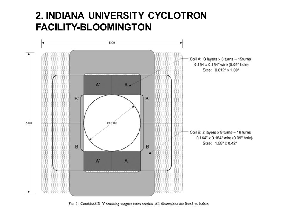
2. INDIANA UNIVERSITY CYCLOTRON FACILITY- BLOOMINGTON

12
3. GSI

Similar presentations


 Undulator Wakes Estimation of CSR Effects for FLASH2HGHG.>")

 modes. Kick is linearly proportional to offset. For offsets close to the axis this is a reasonable approximation.>")
 especially suitable for deep-sited tumors (brain, neck.>")
