Download presentation
Presentation is loading. Please wait.

1
Rodolfo Rodriguez Kevin Zhang MJ Gellada
PIC MICROCONTROLLER Rodolfo Rodriguez Kevin Zhang MJ Gellada

2
Overview Microcontroller and Architecture Basics
Variants among families ISA Programming overview Hardware interface/Developmental boards

3
Description PIC – “Peripheral Interface Controller”
Made by Microchip Technology Most popular by industry developers and hobbyists Low cost (cents to dollars) Availability Extensive application notes Serial programming
 Availability. Extensive application notes. Serial programming.")
4
v

5
8-bit Core Architecture
Harvard (separate code and data space) RISC One accumulator W Register Small addressable data space (256 bytes) Banking RAM PC, special purpose registers
 RISC. One accumulator. W Register. Small addressable data space (256 bytes) Banking. RAM. PC, special purpose registers.")
6
Advantages & Limitations to 8-bit Architecture
Small ISA to learn Built in oscillator with selectable speeds Development made easy Inexpensive Device variants Wide range of interfaces (I2C, SPI, etc.) One accumulator Bank switching Hardware call stack unaddressable (no multi-tasking)
 One accumulator. Bank switching. Hardware call stack unaddressable (no multi-tasking)")
7
16-bit and 32-bit Architecture
More working registers No bank switching Assignable interrupt vector table More flash memory Cache (32-bit architecture)
")
8
Application Notes Very extensive Description of documentation
16758 items Description of documentation PDF documenation Source code

9
8-bit architecture Pin Count 6-40 8-64 18-100 Interrupts No
Baseline Architecture Mid-Range Architecture Enhanced Mid-Range Architecture PIC18 Architecture Pin Count 6-40 8-64 18-100 Interrupts No Single interrupt capability Single interrupt capability with hardware context save Multiple interrupt capability with hardware context save Performance 5 MIPS 8 MIPS Up to 16 MIPS Instructions 33, 12-bit 35, 14-bit 49, 14-bit 83, 16-bit Program Memory Up to 3 KB Up to 14 KB Up to 28 KB Up to 128 KB Data Memory Up to 138 Bytes Up to 368 Bytes Up to 1.5 KB Up to 4 KB Features Comparator 8-bit ADC Internal Oscillator In addition to Baseline: SPI/I²C™ UART PWMs LCD 10-bit ADC Op Amp In addition to Mid-Range: Multiple Communication Peripherals Linear Programming Space PWMs with Independent Time Base In addition to Enhanced Mid-Range: 8x8 Hardware Multiplier CAN CTMU USB Ethernet 12-bit ADC Families PIC10, PIC12, PIC16 PIC12, PIC16 PIC12FXXX, PIC16F1XX PIC18 8-bit architecture

10
0 -> WDT, 1 -> TO, 0 -> PD
PIC16 ISA: 35 Instructions, 14-bit INSTRUCTION DESCRIPTION OPERATION Data Transfer Instructions MOVLW k Move constant to W k -> w MOVWF f Move W to f W -> f MOVF f,d Move f to d f -> d CLRW Clear W 0 -> W CLRF f Clear f 0 -> f SWAPF f,d Swap nibbles in f f(7:4),(3:0) -> f(3:0),(7:4) Arithmetic-logic Instructions ADDLW k Add W and constant W+k -> W ADDWF f,d Add W and f W+f -> d SUBLW k Subtract W from constant k-W -> W SUBWF f,d Subtract W from f f-W -> d ANDLW k Logical AND with W with constant W AND k -> W ANDWF f,d Logical AND with W with f W AND f -> d IORLW k Logical OR with W with constant W OR k -> W IORWF f,d Logical OR with W with f W OR f -> d XORWF f,d Logical exclusive OR with W with constant W XOR k -> W XORLW k Logical exclusive OR with W with f W XOR f -> d INCF f,d Increment f by 1 f+1 -> f DECF f,d Decrement f by 1 f-1 -> f RLF f,d Rotate left f through CARRY bit RRF f,d Rotate right f through CARRY bit COMF f,d Complement f Bit-oriented Instructions BCF f,b Clear bit b in f 0 -> f(b) BSF f,b 1 -> f(b) Program Control Instructions BTFSC f,b Test bit b of f. Skip the following instruction if clear. Skip if f(b) = 0 BTFSS f,b Test bit b of f. Skip the following instruction if set. Skip if f(b) = 1 DECFSZ f,d Decrement f. Skip the following instruction if clear. f-1 -> d skip if Z = 1 INCFSZ f,d Increment f. Skip the following instruction if set. f+1 -> d skip if Z = 0 GOTO k Go to address k -> PC CALL k Call subroutine PC -> TOS, k -> PC RETURN Return from subroutine TOS -> PC RETLW k Return with constant in W k -> W, TOS -> PC RETFIE Return from interrupt TOS -> PC, 1 -> GIE Other instructions NOP No operation CLRWDT Clear watchdog timer 0 -> WDT, 1 -> TO, 1 -> PD SLEEP Go into sleep mode 0 -> WDT, 1 -> TO, 0 -> PD Data Transfer Instructions INSTRUCTION DESCRIPTION OPERATION MOVLW k Move constant to W k -> w MOVWF f Move W to f W -> f MOVF f,d Move f to d f -> d CLRW Clear W 0 -> W CLRF f Clear f 0 -> f SWAPF f,d Swap nibbles in f f(7:4),(3:0) -> f(3:0),(7:4) PIC16 ISA W: Working register(Accumulator) Registers: Memory locations
,(3:0) -> f(3:0),(7:4) Arithmetic-logic Instructions. ADDLW k. Add W and constant. W+k -> W. ADDWF f,d. Add W and f. W+f -> d. SUBLW k. Subtract W from constant. k-W -> W. SUBWF f,d. Subtract W from f. f-W -> d. ANDLW k. Logical AND with W with constant. W AND k -> W. ANDWF f,d. Logical AND with W with f. W AND f -> d. IORLW k. Logical OR with W with constant. W OR k -> W. IORWF f,d. Logical OR with W with f. W OR f -> d. XORWF f,d. Logical exclusive OR with W with constant. W XOR k -> W. XORLW k. Logical exclusive OR with W with f. W XOR f -> d. INCF f,d. Increment f by 1. f+1 -> f. DECF f,d. Decrement f by 1. f-1 -> f. RLF f,d. Rotate left f through CARRY bit. RRF f,d. Rotate right f through CARRY bit. COMF f,d. Complement f. Bit-oriented Instructions. BCF f,b. Clear bit b in f. 0 -> f(b) BSF f,b. 1 -> f(b) Program Control Instructions. BTFSC f,b. Test bit b of f. Skip the following instruction if clear. Skip if f(b) = 0. BTFSS f,b. Test bit b of f. Skip the following instruction if set. Skip if f(b) = 1. DECFSZ f,d. Decrement f. Skip the following instruction if clear. f-1 -> d skip if Z = 1. INCFSZ f,d. Increment f. Skip the following instruction if set. f+1 -> d skip if Z = 0. GOTO k. Go to address. k -> PC. CALL k. Call subroutine. PC -> TOS, k -> PC. RETURN. Return from subroutine. TOS -> PC. RETLW k. Return with constant in W. k -> W, TOS -> PC. RETFIE. Return from interrupt. TOS -> PC, 1 -> GIE. Other instructions. NOP. No operation. CLRWDT. Clear watchdog timer. 0 -> WDT, 1 -> TO, 1 -> PD. SLEEP. Go into sleep mode. 0 -> WDT, 1 -> TO, 0 -> PD. Data Transfer Instructions. INSTRUCTION. DESCRIPTION. OPERATION. MOVLW k. Move constant to W. k -> w. MOVWF f. Move W to f. W -> f. MOVF f,d. Move f to d. f -> d. CLRW. Clear W. 0 -> W. CLRF f. Clear f. 0 -> f. SWAPF f,d. Swap nibbles in f. f(7:4),(3:0) -> f(3:0),(7:4) PIC16 ISA. W: Working register(Accumulator) Registers: Memory locations.")
11
0 -> WDT, 1 -> TO, 0 -> PD
INSTRUCTION DESCRIPTION OPERATION Data Transfer Instructions MOVLW k Move constant to W k -> w MOVWF f Move W to f W -> f MOVF f,d Move f to d f -> d CLRW Clear W 0 -> W CLRF f Clear f 0 -> f SWAPF f,d Swap nibbles in f f(7:4),(3:0) -> f(3:0),(7:4) Arithmetic-logic Instructions ADDLW k Add W and constant W+k -> W ADDWF f,d Add W and f W+f -> d SUBLW k Subtract W from constant k-W -> W SUBWF f,d Subtract W from f f-W -> d ANDLW k Logical AND with W with constant W AND k -> W ANDWF f,d Logical AND with W with f W AND f -> d IORLW k Logical OR with W with constant W OR k -> W IORWF f,d Logical OR with W with f W OR f -> d XORWF f,d Logical exclusive OR with W with constant W XOR k -> W XORLW k Logical exclusive OR with W with f W XOR f -> d INCF f,d Increment f by 1 f+1 -> f DECF f,d Decrement f by 1 f-1 -> f RLF f,d Rotate left f through CARRY bit RRF f,d Rotate right f through CARRY bit COMF f,d Complement f Bit-oriented Instructions BCF f,b Clear bit b in f 0 -> f(b) BSF f,b 1 -> f(b) Program Control Instructions BTFSC f,b Test bit b of f. Skip the following instruction if clear. Skip if f(b) = 0 BTFSS f,b Test bit b of f. Skip the following instruction if set. Skip if f(b) = 1 DECFSZ f,d Decrement f. Skip the following instruction if clear. f-1 -> d skip if Z = 1 INCFSZ f,d Increment f. Skip the following instruction if set. f+1 -> d skip if Z = 0 GOTO k Go to address k -> PC CALL k Call subroutine PC -> TOS, k -> PC RETURN Return from subroutine TOS -> PC RETLW k Return with constant in W k -> W, TOS -> PC RETFIE Return from interrupt TOS -> PC, 1 -> GIE Other instructions NOP No operation CLRWDT Clear watchdog timer 0 -> WDT, 1 -> TO, 1 -> PD SLEEP Go into sleep mode 0 -> WDT, 1 -> TO, 0 -> PD Arithmetic-logic Instructions (partial) ADDLW k Add W and constant W+k -> W ADDWF f,d Add W and f W+f -> d INCF f,d Increment f by 1 f+1 -> f DECF f,d Decrement f by 1 f-1 -> f RLF f,d Rotate left f through CARRY bit RRF f,d Rotate right f through CARRY bit COMF f,d Complement f f -> d PIC16 ISA SUBLW, SUBWF ANDLW, ANDWF IORLW, IORWF XORLW, XORWF
,(3:0) -> f(3:0),(7:4) Arithmetic-logic Instructions. ADDLW k. Add W and constant. W+k -> W. ADDWF f,d. Add W and f. W+f -> d. SUBLW k. Subtract W from constant. k-W -> W. SUBWF f,d. Subtract W from f. f-W -> d. ANDLW k. Logical AND with W with constant. W AND k -> W. ANDWF f,d. Logical AND with W with f. W AND f -> d. IORLW k. Logical OR with W with constant. W OR k -> W. IORWF f,d. Logical OR with W with f. W OR f -> d. XORWF f,d. Logical exclusive OR with W with constant. W XOR k -> W. XORLW k. Logical exclusive OR with W with f. W XOR f -> d. INCF f,d. Increment f by 1. f+1 -> f. DECF f,d. Decrement f by 1. f-1 -> f. RLF f,d. Rotate left f through CARRY bit. RRF f,d. Rotate right f through CARRY bit. COMF f,d. Complement f. Bit-oriented Instructions. BCF f,b. Clear bit b in f. 0 -> f(b) BSF f,b. 1 -> f(b) Program Control Instructions. BTFSC f,b. Test bit b of f. Skip the following instruction if clear. Skip if f(b) = 0. BTFSS f,b. Test bit b of f. Skip the following instruction if set. Skip if f(b) = 1. DECFSZ f,d. Decrement f. Skip the following instruction if clear. f-1 -> d skip if Z = 1. INCFSZ f,d. Increment f. Skip the following instruction if set. f+1 -> d skip if Z = 0. GOTO k. Go to address. k -> PC. CALL k. Call subroutine. PC -> TOS, k -> PC. RETURN. Return from subroutine. TOS -> PC. RETLW k. Return with constant in W. k -> W, TOS -> PC. RETFIE. Return from interrupt. TOS -> PC, 1 -> GIE. Other instructions. NOP. No operation. CLRWDT. Clear watchdog timer. 0 -> WDT, 1 -> TO, 1 -> PD. SLEEP. Go into sleep mode. 0 -> WDT, 1 -> TO, 0 -> PD. Arithmetic-logic Instructions (partial) ADDLW k. Add W and constant. W+k -> W. ADDWF f,d. Add W and f. W+f -> d. INCF f,d. Increment f by 1. f+1 -> f. DECF f,d. Decrement f by 1. f-1 -> f. RLF f,d. Rotate left f through CARRY bit. RRF f,d. Rotate right f through CARRY bit. COMF f,d. Complement f. f -> d. PIC16 ISA. SUBLW, SUBWF. ANDLW, ANDWF. IORLW, IORWF. XORLW, XORWF.")
12
0 -> WDT, 1 -> TO, 0 -> PD
INSTRUCTION DESCRIPTION OPERATION Data Transfer Instructions MOVLW k Move constant to W k -> w MOVWF f Move W to f W -> f MOVF f,d Move f to d f -> d CLRW Clear W 0 -> W CLRF f Clear f 0 -> f SWAPF f,d Swap nibbles in f f(7:4),(3:0) -> f(3:0),(7:4) Arithmetic-logic Instructions ADDLW k Add W and constant W+k -> W ADDWF f,d Add W and f W+f -> d SUBLW k Subtract W from constant k-W -> W SUBWF f,d Subtract W from f f-W -> d ANDLW k Logical AND with W with constant W AND k -> W ANDWF f,d Logical AND with W with f W AND f -> d IORLW k Logical OR with W with constant W OR k -> W IORWF f,d Logical OR with W with f W OR f -> d XORWF f,d Logical exclusive OR with W with constant W XOR k -> W XORLW k Logical exclusive OR with W with f W XOR f -> d INCF f,d Increment f by 1 f+1 -> f DECF f,d Decrement f by 1 f-1 -> f RLF f,d Rotate left f through CARRY bit RRF f,d Rotate right f through CARRY bit COMF f,d Complement f Bit-oriented Instructions BCF f,b Clear bit b in f 0 -> f(b) BSF f,b 1 -> f(b) Program Control Instructions BTFSC f,b Test bit b of f. Skip the following instruction if clear. Skip if f(b) = 0 BTFSS f,b Test bit b of f. Skip the following instruction if set. Skip if f(b) = 1 DECFSZ f,d Decrement f. Skip the following instruction if clear. f-1 -> d skip if Z = 1 INCFSZ f,d Increment f. Skip the following instruction if set. f+1 -> d skip if Z = 0 GOTO k Go to address k -> PC CALL k Call subroutine PC -> TOS, k -> PC RETURN Return from subroutine TOS -> PC RETLW k Return with constant in W k -> W, TOS -> PC RETFIE Return from interrupt TOS -> PC, 1 -> GIE Other instructions NOP No operation CLRWDT Clear watchdog timer 0 -> WDT, 1 -> TO, 1 -> PD SLEEP Go into sleep mode 0 -> WDT, 1 -> TO, 0 -> PD Program Control Instructions BTFSC f,b Test bit b of f. Skip the following instruction if clear. Skip if f(b) = 0 BTFSS f,b Test bit b of f. Skip the following instruction if set. Skip if f(b) = 1 DECFSZ f,d Decrement f. Skip the following instruction if clear. f-1 -> d skip if Z = 1 INCFSZ f,d Increment f. Skip the following instruction if set. f+1 -> d skip if Z = 0 GOTO k Go to address k -> PC CALL k Call subroutine PC -> TOS, k -> PC RETURN Return from subroutine TOS -> PC RETLW k Return with constant in W k -> W, TOS -> PC RETFIE Return from interrupt TOS -> PC, 1 -> GIE PIC16 ISA
,(3:0) -> f(3:0),(7:4) Arithmetic-logic Instructions. ADDLW k. Add W and constant. W+k -> W. ADDWF f,d. Add W and f. W+f -> d. SUBLW k. Subtract W from constant. k-W -> W. SUBWF f,d. Subtract W from f. f-W -> d. ANDLW k. Logical AND with W with constant. W AND k -> W. ANDWF f,d. Logical AND with W with f. W AND f -> d. IORLW k. Logical OR with W with constant. W OR k -> W. IORWF f,d. Logical OR with W with f. W OR f -> d. XORWF f,d. Logical exclusive OR with W with constant. W XOR k -> W. XORLW k. Logical exclusive OR with W with f. W XOR f -> d. INCF f,d. Increment f by 1. f+1 -> f. DECF f,d. Decrement f by 1. f-1 -> f. RLF f,d. Rotate left f through CARRY bit. RRF f,d. Rotate right f through CARRY bit. COMF f,d. Complement f. Bit-oriented Instructions. BCF f,b. Clear bit b in f. 0 -> f(b) BSF f,b. 1 -> f(b) Program Control Instructions. BTFSC f,b. Test bit b of f. Skip the following instruction if clear. Skip if f(b) = 0. BTFSS f,b. Test bit b of f. Skip the following instruction if set. Skip if f(b) = 1. DECFSZ f,d. Decrement f. Skip the following instruction if clear. f-1 -> d skip if Z = 1. INCFSZ f,d. Increment f. Skip the following instruction if set. f+1 -> d skip if Z = 0. GOTO k. Go to address. k -> PC. CALL k. Call subroutine. PC -> TOS, k -> PC. RETURN. Return from subroutine. TOS -> PC. RETLW k. Return with constant in W. k -> W, TOS -> PC. RETFIE. Return from interrupt. TOS -> PC, 1 -> GIE. Other instructions. NOP. No operation. CLRWDT. Clear watchdog timer. 0 -> WDT, 1 -> TO, 1 -> PD. SLEEP. Go into sleep mode. 0 -> WDT, 1 -> TO, 0 -> PD. Program Control Instructions. BTFSC f,b. Test bit b of f. Skip the following instruction if clear. Skip if f(b) = 0. BTFSS f,b. Test bit b of f. Skip the following instruction if set. Skip if f(b) = 1. DECFSZ f,d. Decrement f. Skip the following instruction if clear. f-1 -> d skip if Z = 1. INCFSZ f,d. Increment f. Skip the following instruction if set. f+1 -> d skip if Z = 0. GOTO k. Go to address. k -> PC. CALL k. Call subroutine. PC -> TOS, k -> PC. RETURN. Return from subroutine. TOS -> PC. RETLW k. Return with constant in W. k -> W, TOS -> PC. RETFIE. Return from interrupt. TOS -> PC, 1 -> GIE. PIC16 ISA.")
13
0 -> WDT, 1 -> TO, 0 -> PD
INSTRUCTION DESCRIPTION OPERATION Data Transfer Instructions MOVLW k Move constant to W k -> w MOVWF f Move W to f W -> f MOVF f,d Move f to d f -> d CLRW Clear W 0 -> W CLRF f Clear f 0 -> f SWAPF f,d Swap nibbles in f f(7:4),(3:0) -> f(3:0),(7:4) Arithmetic-logic Instructions ADDLW k Add W and constant W+k -> W ADDWF f,d Add W and f W+f -> d SUBLW k Subtract W from constant k-W -> W SUBWF f,d Subtract W from f f-W -> d ANDLW k Logical AND with W with constant W AND k -> W ANDWF f,d Logical AND with W with f W AND f -> d IORLW k Logical OR with W with constant W OR k -> W IORWF f,d Logical OR with W with f W OR f -> d XORWF f,d Logical exclusive OR with W with constant W XOR k -> W XORLW k Logical exclusive OR with W with f W XOR f -> d INCF f,d Increment f by 1 f+1 -> f DECF f,d Decrement f by 1 f-1 -> f RLF f,d Rotate left f through CARRY bit RRF f,d Rotate right f through CARRY bit COMF f,d Complement f Bit-oriented Instructions BCF f,b Clear bit b in f 0 -> f(b) BSF f,b 1 -> f(b) Program Control Instructions BTFSC f,b Test bit b of f. Skip the following instruction if clear. Skip if f(b) = 0 BTFSS f,b Test bit b of f. Skip the following instruction if set. Skip if f(b) = 1 DECFSZ f,d Decrement f. Skip the following instruction if clear. f-1 -> d skip if Z = 1 INCFSZ f,d Increment f. Skip the following instruction if set. f+1 -> d skip if Z = 0 GOTO k Go to address k -> PC CALL k Call subroutine PC -> TOS, k -> PC RETURN Return from subroutine TOS -> PC RETLW k Return with constant in W k -> W, TOS -> PC RETFIE Return from interrupt TOS -> PC, 1 -> GIE Other instructions NOP No operation CLRWDT Clear watchdog timer 0 -> WDT, 1 -> TO, 1 -> PD SLEEP Go into sleep mode 0 -> WDT, 1 -> TO, 0 -> PD Bit-oriented Instructions BCF f,b Clear bit b in f 0 -> f(b) BSF f,b Set bit b in f 1 -> f(b) PIC16 ISA Other instructions NOP No operation TOS -> PC, 1 -> GIE CLRWDT Clear watchdog timer 0 -> WDT, 1 -> TO, 1 -> PD SLEEP Go into sleep mode 0 -> WDT, 1 -> TO, 0 -> PD
,(3:0) -> f(3:0),(7:4) Arithmetic-logic Instructions. ADDLW k. Add W and constant. W+k -> W. ADDWF f,d. Add W and f. W+f -> d. SUBLW k. Subtract W from constant. k-W -> W. SUBWF f,d. Subtract W from f. f-W -> d. ANDLW k. Logical AND with W with constant. W AND k -> W. ANDWF f,d. Logical AND with W with f. W AND f -> d. IORLW k. Logical OR with W with constant. W OR k -> W. IORWF f,d. Logical OR with W with f. W OR f -> d. XORWF f,d. Logical exclusive OR with W with constant. W XOR k -> W. XORLW k. Logical exclusive OR with W with f. W XOR f -> d. INCF f,d. Increment f by 1. f+1 -> f. DECF f,d. Decrement f by 1. f-1 -> f. RLF f,d. Rotate left f through CARRY bit. RRF f,d. Rotate right f through CARRY bit. COMF f,d. Complement f. Bit-oriented Instructions. BCF f,b. Clear bit b in f. 0 -> f(b) BSF f,b. 1 -> f(b) Program Control Instructions. BTFSC f,b. Test bit b of f. Skip the following instruction if clear. Skip if f(b) = 0. BTFSS f,b. Test bit b of f. Skip the following instruction if set. Skip if f(b) = 1. DECFSZ f,d. Decrement f. Skip the following instruction if clear. f-1 -> d skip if Z = 1. INCFSZ f,d. Increment f. Skip the following instruction if set. f+1 -> d skip if Z = 0. GOTO k. Go to address. k -> PC. CALL k. Call subroutine. PC -> TOS, k -> PC. RETURN. Return from subroutine. TOS -> PC. RETLW k. Return with constant in W. k -> W, TOS -> PC. RETFIE. Return from interrupt. TOS -> PC, 1 -> GIE. Other instructions. NOP. No operation. CLRWDT. Clear watchdog timer. 0 -> WDT, 1 -> TO, 1 -> PD. SLEEP. Go into sleep mode. 0 -> WDT, 1 -> TO, 0 -> PD. Bit-oriented Instructions. BCF f,b. Clear bit b in f. 0 -> f(b) BSF f,b. Set bit b in f. 1 -> f(b) PIC16 ISA. Other instructions. NOP. No operation. TOS -> PC, 1 -> GIE. CLRWDT. Clear watchdog timer. 0 -> WDT, 1 -> TO, 1 -> PD. SLEEP. Go into sleep mode. 0 -> WDT, 1 -> TO, 0 -> PD.")
14
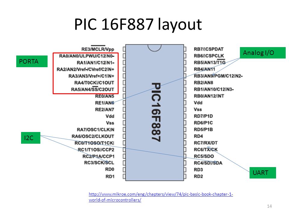
PIC 16F887 layout Analog I/O PORTA I2C UART
15
Programming a PIC Microchip provides the free MPLAB: Compiler
Assembler and linker Application development Hardware emulation Debugging C or assembly compatible Compiler Can be C-based or Basic A free one is the CCS C Compiler for PIC12/24/26/18 (not compatible with all PICS) or the HI-TECH PICC-Lit
 or the HI-TECH PICC-Lit.")
16
Programming Tools Basic based environments are available, but don’t offer the functionality of C Third party IDE’s might be preferred due to an enhanced software library or debugging tools

17
Device Programmer Need device to store machine code into PIC’s memory (EEPROM or Flash) Can be external device, but ICSP is easier: Don’t have to remove chip from its circuit Provides interface between computer (USB) and PIC Specific to circuit (due to interconnect scheme and surrounding circuit) Communication protocol requires 5 signals The data is transferred using a two wire synchronous serial scheme, three more wires provide programming and chip power. The clock signal is always controlled by the programmer.
 and PIC. Specific to circuit (due to interconnect scheme and surrounding circuit) Communication protocol requires 5 signals. The data is transferred using a two wire synchronous serial scheme, three more wires provide programming and chip power. The clock signal is always controlled by the programmer.")
18
Device Programmer Five Signals: Vpp (programming voltage) Vdd (power)
Vss (ground) IC SPCLK (clock) IC SPDAT (data) Vpp - Programming mode voltage. This must be connected to the MCLR pin, or the Vpp pin of the optional ICSP port available on some large-pincount PICs. To put the PIC into programming mode, this line must be in a specified range that varies from PIC to PIC. For 5V PICs, this is always some amount above Vdd, and can be as high as 13.5V. The 3.3V only PICs like the 18FJ, 24H, and 33F series use a special signature to enter programming mode and Vpp is a digital signal that is either at ground or Vdd. There is no one Vpp voltage that is within the valid Vpp range of all PICs. In fact, the minimum required Vpp level for some PICs can damage other PICs. Vdd - This is the positive power input to the PIC. Some programmers require this to be provided by the circuit (circuit must be at least partially powered up), some programmers expect to drive this line themselves and require the circuit to be off, while others can be configured either way (like the Microchip ICD2). The Embed Inc programmers expect to drive the Vdd line themselves and require the target circuit to be off during programming. Vss - Negative power input to the PIC and the zero volts reference for the remaining signals. Voltages of the other signals are implicitly with respect to Vss. ICSPCLK - Clock line of the serial data interface. This line swings from GND to Vdd and is always driven by the programmer. Data is transferred on the falling edge. ICSPDAT - Serial data line. The serial interface is bi-directional, so this line can be driven by either the programmer or the PIC depending on the current operation. In either case this line swings from GND to Vdd. A bit is transferred on the falling edge of PGC. 1. Select device 2. Load HEX file 3. Program PIC
 IC SPCLK (clock) IC SPDAT (data) Vpp - Programming mode voltage. This must be connected to the MCLR pin, or the Vpp pin of the optional ICSP port available on some large-pincount PICs. To put the PIC into programming mode, this line must be in a specified range that varies from PIC to PIC. For 5V PICs, this is always some amount above Vdd, and can be as high as 13.5V. The 3.3V only PICs like the 18FJ, 24H, and 33F series use a special signature to enter programming mode and Vpp is a digital signal that is either at ground or Vdd. There is no one Vpp voltage that is within the valid Vpp range of all PICs. In fact, the minimum required Vpp level for some PICs can damage other PICs. Vdd - This is the positive power input to the PIC. Some programmers require this to be provided by the circuit (circuit must be at least partially powered up), some programmers expect to drive this line themselves and require the circuit to be off, while others can be configured either way (like the Microchip ICD2). The Embed Inc programmers expect to drive the Vdd line themselves and require the target circuit to be off during programming. Vss - Negative power input to the PIC and the zero volts reference for the remaining signals. Voltages of the other signals are implicitly with respect to Vss. ICSPCLK - Clock line of the serial data interface. This line swings from GND to Vdd and is always driven by the programmer. Data is transferred on the falling edge. ICSPDAT - Serial data line. The serial interface is bi-directional, so this line can be driven by either the programmer or the PIC depending on the current operation. In either case this line swings from GND to Vdd. A bit is transferred on the falling edge of PGC. 1. Select device. 2. Load HEX file. 3. Program PIC.")
19
Necessary Connections (PIC16F877A)
PIC can be bread-boarded, with the following important connections: Power Ground Reset signal Crystal (oscillator)
")
20
LED example: code //LED example program written for //PIC programming tutorial. From //( //standard include files #include <stdlib.h> #include <pic.h> #include “delay.h” //main function void main() { PORTA = 0x00; //set RA0-RA5 low TRISA = 0x00; //set PORTA to output //superloop while(1) PORTA = ~PORTA; DelayMs(250); }
 { PORTA = 0x00; //set RA0-RA5 low TRISA = 0x00; //set PORTA to output //superloop while(1) PORTA = ~PORTA; DelayMs(250); }")
21
Development Boards Prepackaged boards come with a multitude of peripherals for development and debugging: Programmer User I/O: buttons, port pinouts, LED’s Displays: LCD and seven segment Power Serial connection interface

22
Easy PIC v7 from MikroElectronika
USB Port Programmer PIC Power Supply LEDs and buttons Port Pinouts

23
Additional Peripherals
Touch Screen ADC converter

24
Questions?

25
References http://www.microchip.com/

Similar presentations


 are all contained in a single package.>")


