Download presentation
Presentation is loading. Please wait.

1
By Sherjeel Farooqui

2
Wireless Local Area Network Wireless local area networks (LANs) are a new breed of LANs that use airwaves instead of a physical medium (wires or cables) to interconnect computers. Wireless LAN can be connected to a wired LAN: as an extension or can form the basis for a new network

3
Why Wireless LAN? Problems of creating a wired network where cabling is not possible or feasible. Companies want their LAN wirings to be altered frequently. Companies want to introduce mobility apart from a traditional wired network in place. There are places where laying and running network cables are almost impossible.

4
Wireless Advantages Mobility Ease and speed of deployment Flexibility Cost

5
WLAN 802.11b A wireless local area network protocol which allows high speed access to network resources. It operates at 11 megabits per second. (depending on distance). It uses the 2.4 Ghz spectrum. 802.11b uses Direct Sequence Spread Spectrum (DSSS) Phase Shift Keying (PSK). Frequency Hopping Spread Spectrum (FHSS) Frequency Shift Keying (FSK).
. It uses the 2.4 Ghz spectrum b uses Direct Sequence Spread Spectrum (DSSS) Phase Shift Keying (PSK). Frequency Hopping Spread Spectrum (FHSS) Frequency Shift Keying (FSK)..")
6
WLAN STANDARDS IEEE 802.11b – 11Mbps/2.4GHz band Operates in the ISM Frequency Band Divided into 11 Channels for use. IEEE 802.11g – 22Mbps/2.4GHz band IEEE 802.11e – Quality of Service Extensions IEEE 802.11a – 54Mbps/5GHz band

7
IEEE 802.11 Standards StandardSpectrumBit RateTransmissionQuality of Service Compatibility 802.11wavelength between 850 and 950 nm; 2.4 GHz 2 MbpsInfrared / FHSS / DSSS NoN/A 802.11b (Wi-Fi) 2.4 GHz11 MbpsDSSSNo802.11 802.11a5.0 GHz54 MbpsOFDMNoNone 802.11g2.4 GHz54 MbpsOFDMNo802.11/ 802.11b 802.11e2.5/5.0 GHz11/54MbpsOFDM/DSSSYes802.11a/ 802.11b 802.11n 2.5/5.0 GHz 200/500Mbps OFDM/DSSSYes -
 2.4 GHz11 MbpsDSSSNo a5.0 GHz54 MbpsOFDMNoNone g2.4 GHz54 MbpsOFDMNo802.11/ b e2.5/5.0 GHz11/54MbpsOFDM/DSSSYes802.11a/ b n 2.5/5.0 GHz 200/500Mbps OFDM/DSSSYes -")
8
IEEE 802.11 Architecture Distribution system (DS) Access point (AP) Basic service set (BSS) Stations competing for access to shared wireless medium Isolated or connected to backbone DS through AP Extended service set (ESS) Two or more basic service sets interconnected by DS
 Access point (AP) Basic service set (BSS) Stations competing for access to shared wireless medium Isolated or connected to backbone DS through AP Extended service set (ESS) Two or more basic service sets interconnected by DS")
9
Types Of 802.11 Networks Ad-hoc Networks Stations wireless medium Infrastructure Networks Access Point Stations Wireless Medium Distribution System

10
Ad-hoc Network Temporary set of stations Forming as ad-hoc network – an independent BSS (IBSS), means that there is no connection to wired network No AP No relay function (direct connection) Simple setup
, means that there is no connection to wired network No AP No relay function (direct connection) Simple setup")
11
A-hoc Network No Relay Direct connection

12
Infrastructure Networks Access Point (AP) is used. AP is used for all types of communication including communication between stations in the same service area. Originating station transfer frames to AP. AP transfer frames to destination station. All stations should be in the range of AP.

13
The IEEE 802.11 Wireless LAN architecture Wireless LAN Station (STA) Access Points (AP) Basic Service Set (BSS) Distribution System (DS) Extended Service Set (ESS)
 Access Points (AP) Basic Service Set (BSS) Distribution System (DS) Extended Service Set (ESS)")
14
AP’s & Stations Each node in the 802.11 network may be station (STA) or and access point In definition AP contains a station. No limit on a number of stations an AP can serve.

15
Basic Service set (BSS) Set of arbitrary stations, and one AP. Station have to be associated with the AP in order to be part of the BSS Local relay function through the AP. Advantage : When station is in power saving mode the AP will buffer traffic for the (sleeping) mobile station. Disadvantage: Consume twice bandwidth
 mobile station. Disadvantage: Consume twice bandwidth.")
16
Basic Service Set (BSS) BSS
 BSS")
17
Basic Service Set (BSS) BSS AP STA
 BSS AP STA")
18
Extended Service Set (ESS) An ESS can be created by chaining BSS together with the backbone network. The APs communicate among themselves to form relay between the BSS domains, through abstract distribution system (DS) Wireless network of arbitrary large size can be created by linking BSS into ESS
 Wireless network of arbitrary large size can be created by linking BSS into ESS.")
19
WLAN 802.11 Network BSS DS (usually Ethernet) ESS AP STA BSS AP STA
 ESS AP STA BSS AP STA")
20
Distribution System (DS) Logical communication between the APs The DS is the backbone of the WLAN and may be constructed over wired or wireless connection. The communication between the APs over the DS, is not in the scope of 802.11 protocol.

21
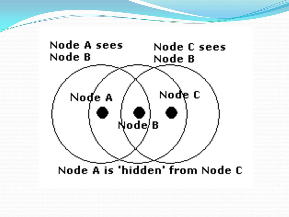
The Hidden Node Problem The hidden node problem occurs in a point to multi-point network and is defined as being one in which three (or more nodes) are present. Node A, Node B and Node C. It is possible that in this case Node B can hear Node A (and vice versa) and Node B can hear Node C (and vice versa) BUT Node C cannot hear Node A. In a CSMA/CA environment Nodes A and C would both properly transmit (they cannot hear each other on the 'listen' phase so could both simultaneously and properly transmit a packet) but Node B would get corrupted data. Nodes A and C are said to be 'hidden' from each other.
 and Node B can hear Node C (and vice versa) BUT Node C cannot hear Node A. In a CSMA/CA environment Nodes A and C would both properly transmit (they cannot hear each other on the listen phase so could both simultaneously and properly transmit a packet) but Node B would get corrupted data. Nodes A and C are said to be hidden from each other..")
23
Hidden Node Problem Problems A Send data to B C can disturb transmition A B because C can’t hear A A B C

24
Extended Service Set (ESS) BSS’s with wired Distribution System (DS) BSS Distribution System
 BSS’s with wired Distribution System (DS) BSS Distribution System")
25
Extended Service Set (ESS) BSS’s and wireless Distribution System (DS) BSS Distribution System
 BSS’s and wireless Distribution System (DS) BSS Distribution System")
26
802.11 & ISO Model

27
Distance & Speed

28
IEEE 802 Overview

29
Services Station services: authentication, de-authentication, privacy, delivery of data Distribution Services ( A thin layer between MAC and LLC sublayer) association disassociation reassociation distribution Integration A station maintain two variables: authentication state (=> 1) association state (<= 1)
 association disassociation reassociation distribution Integration A station maintain two variables: authentication state (=> 1) association state (<= 1)")
30
Distribution of Messages Within a DS Distribution service Used to exchange MAC frames from station in one BSS to station in another BSS Integration service Transfer of data between station on IEEE 802.11 LAN and station on integrated IEEE 802.x LAN

31
Transition Types Based On Mobility No transition Stationary or moves only within BSS BSS transition Station moving from one BSS to another BSS in same ESS ESS transition Station moving from BSS in one ESS to BSS within another ESS

32
Association-Related Services Association Establishes initial association between station and AP Reassociation Enables transfer of association from one AP to another, allowing station to move from one BSS to another Disassociation Association termination notice from station or AP

33
Access and Privacy Services Authentication Establishes identity of stations to each other Deathentication Invoked when existing authentication is terminated Privacy Prevents message contents from being read by unintended recipient

34
IEEE 802.11 Services

35
IEEE 802 Protocol Layers

36
IEEE 802.11 Terminology Service Set Identifier (SSID): “Network name” 32 octets long Similar to “Domain-ID” in the pre-IEEE WaveLAN systems One network (ESS or IBSS) has one SSID. Portal: A bridging device to link 802.11 network with external 802 networks.

37
Ex.

38
Scanning & Joining Scanning Passive Scanning : only listens for Beacon and get info of the BSS. Power is saved. Active Scanning: transmit and elicit response from APs. If IBSS, last station that transmitted beacon responds. Time is saved. Joining a BSS Synchronization in TSF and frequency : Adopt PHY parameters : The BSSID : WEP : Beacon Period : DTIM

39
Protocol Architecture Functions of physical layer: Provide an interface/services to higher layer and perform flow and error control. Encoding/decoding of signals Preamble generation/removal (for synchronization) Bit transmission/reception On transmission assembles data into a frame with address and error detection fields. On reception disassemble frame and perform address recognition and error detection Govern access to LAN transmission medium Includes specification of the transmission medium.
 Bit transmission/reception On transmission assembles data into a frame with address and error detection fields. On reception disassemble frame and perform address recognition and error detection Govern access to LAN transmission medium Includes specification of the transmission medium..")
40
Physical Layer Physical Layer Convergence Procedure(PLCP). Defines the method of mapping 802.11 MAC Layer Protocol data units (MPDU). Into framing format suitable for sending and receiving user data. Management information between two or more stations using the associated PMD sub layer. Physical Medium dependent sublayer (PMD). Defines the characteristics of and method of transmitting and receiving user data through a wire less medium between two or more station.
. Into framing format suitable for sending and receiving user data. Management information between two or more stations using the associated PMD sub layer. Physical Medium dependent sublayer (PMD). Defines the characteristics of and method of transmitting and receiving user data through a wire less medium between two or more station..")
41
Power Save Mode The optional power save mode that a user can turn on or off enables the radio NIC to conserve battery power when there is no need to send data.power save mode With power save mode on, the radio NIC indicates its desire to enter "sleep" state to the access point via a status bit located in the header of each frame. The access point takes note of each radio NIC wishing to enter power save mode, and buffers packets corresponding to the sleeping station. In order to still receive data frames, the sleeping NIC must wake up periodically (at the right time) to receive regular beacon transmissions coming from the access point. These beacons identify whether sleeping stations have frames buffered at the access point and waiting for delivery to their respective destinations. The radio NICs having awaiting frames will request them from the access point. After receiving the frames, the radio NIC can go back to sleep
 to receive regular beacon transmissions coming from the access point. These beacons identify whether sleeping stations have frames buffered at the access point and waiting for delivery to their respective destinations. The radio NICs having awaiting frames will request them from the access point. After receiving the frames, the radio NIC can go back to sleep.")
42
Timing Intervals There are five timing intervals. 1) the short interframe space (SIFS) 2) PHY determines: the slot time. 3) The priority interframe space (PIFS), 4) The distributed interframe space (DIFS), 5)The extended interframe space (EIFS).
 the short interframe space (SIFS) 2) PHY determines: the slot time. 3) The priority interframe space (PIFS), 4) The distributed interframe space (DIFS), 5)The extended interframe space (EIFS)..")
43
Timing Intervals The SIFS is the shortest interval, followed by the slot time which is slightly longer. The PIFS is equal to SIFS plus one slot time. The DIFS is equal to the SIFS plus two slot times. The EIFS is much larger than any of the other intervals. It is used when a frame that contains errors is received by the MAC, allowing the possibility for the MAC frame exchanges to complete correctly before another transmission is allowed Through these five timing intervals, both the DCF and PCF are implemented.

44
Transmission Specifics CSMA/CA Interval durations: DIFS= 50 µs SIFS= 10 µs Defer Access Slot time Select slot and decrement backoff Backoff windowNext Frame Contention Window DIFS PIFS SIFS Busy Medium DIFS Immediate access if medium is free >= DIFS

45
MAC coordination functions

46
Carrier-Sensing Functions and the Network Allocation Vector Carrier sensing is used to determine if the medium is available. Two types of carrier sensing functions in 802.11 manage this process: the physical carrier-sensing and virtual carrier-sensing functions. with hidden nodes potentially lurking everywhere, physical carrier-sensing cannot provide all the necessary information. Virtual carrier-sensing is provided by the Network Allocation Vector (NAV). Most 802.11 frames carry a duration field, which can be used to reserve the medium for a fixed time period.
. Most frames carry a duration field, which can be used to reserve the medium for a fixed time period..")
47
Carrier-Sensing Functions and the Network Allocation Vector Stations count down from the NAV to 0. By using the NAV, stations can ensure that atomic operations are not interrupted. To ensure that the sequence is not interrupted, node 1 sets the NAV in its RTS to block access to the medium. RTS frames are not necessarily heard by every station in the network. Therefore, the recipient of the intended transmission responds with a CTS that includes a shorter NAV. This NAV prevents other stations from accessing the medium until the transmission completes.

48
Using the NAV for virtual carrier sensing

49
Contention-Based Access Using the DCF The DCF allows multiple independent stations to interact without central control. It may be used in either IBSS networks or in infrastructure networks. Before attempting to transmit, each station checks whether the medium is idle. If the medium is not idle, stations defer to each other and employ an orderly exponential backoff algorithm to avoid collisions.

50
Contention-Based Access Using the DCF Two basic rules apply to all transmissions using the DCF If the medium has been idle for longer than the DIFS, transmission can begin immediately. Carrier sensing is performed using both a physical medium dependent method and the virtual (NAV) method. If the previous frame was received without errors, the medium must be free for at least the DIFS. If the previous transmission contained errors, the medium must be free for the amount of the EIFS. If the medium is busy, the station must wait for the channel to become idle. 802.11 refers to the wait as access deferral
 method. If the previous frame was received without errors, the medium must be free for at least the DIFS. If the previous transmission contained errors, the medium must be free for the amount of the EIFS. If the medium is busy, the station must wait for the channel to become idle refers to the wait as access deferral.")
51
Additional rules Error recovery is the responsibility of the station sending a frame. Positive acknowledgments are the only indication of success. Atomic exchanges must complete in their entirety to be successful. If an acknowledgment is expected and does not arrive, the sender considers the transmission lost and must retry. All unicast data must be acknowledged. Multiframe sequences may update the NAV with each step in the transmission procedure. When a station receives a medium reservation that is longer than the current NAV, it updates the NAV. Setting the NAV is done on a frame- by-frame basis.

52
The following types of frames can be transmitted after the SIFS Once a station has transmitted the first frame in a sequence, it has gained control of the channel. Any additional frames and their acknowledgments can be sent using the short interframe space, which locks out any other stations. Additional frames in the sequence update the NAV for the expected additional time the medium will be used.

53
Error Recovery with the DCF Error detection and correction is up to the station that begins an atomic frame exchange. When an error is detected, the station with data must resend the frame. the sender can infer frame loss by the lack of a positive acknowledgment from the receiver.

54
DSSS contention window size

55
NAV Settings SIFS – Short Interframe Space DIFS – Distributed Interframe space DIFS RTS SIFS CTS Data SIFS ACK DIFS NAV (RTS) NAV (CTS) Defer AccessBackoff Next transmition SIFS Source Destination Other
 NAV (CTS) Defer AccessBackoff Next transmition SIFS Source Destination Other")
56
DCF Operation (Timing of the 802.11 DCF. In this example, station 6 cannot detect the RTS frame of the transmitting station 2, but the CTS frame of station 1.)
.")
57
Point Coordination Function (PCF) Uses a poll and response protocol to eliminate the possibility of contention for the medium. It is also known as Centrally Controlled Access Mechanism. A point coordinator (PC) controls the PCF. The PC is always located in an AP. The PCF uses PIFS and SIFS instead of DIFS so that no DCF communication can take place. Polling list is maintained when ever station is associated with the AP. During contention free period only station with permission by AP can transmit frame.
 controls the PCF. The PC is always located in an AP. The PCF uses PIFS and SIFS instead of DIFS so that no DCF communication can take place. Polling list is maintained when ever station is associated with the AP. During contention free period only station with permission by AP can transmit frame..")
58
Types of Frames in DCF Several different frame types can be used in the contention free period: Data The standard vanilla Data frame is used when the access point is sending a frame to a station and does not need to acknowledge a previous transmission. The standard Data frame does not poll the recipient and thus does not allow the recipient to transmit any data in return. The Data-Only frame used in the contention-free period is identical to the Data frame used in contention-based periods. CF-Ack This frame is used by stations to acknowledge the receipt of a frame when no data needs to be transmitted. Contention-free acknowledgments are longer than the standard control frame acknowledgment, so this frame may not be used in actual implementations.

59
Types of Frames in DCF CF-Poll CF-Poll frames are sent by the access point to a mobile station to give the mobile station the right to transmit a single buffered frame. It is used when the access point does not have any data for the mobile station. When a frame for the mobile station is available, the access point uses the Data+CF-Poll frame type. Data+CF-Ack This frame combines data transmission with an acknowledgment. Data is directed to the frame recipient; the acknowledgment is for the previous frame transmitted and usually is not for the recipient of the data.

60
Types of Frames in DCF Data+CF-Poll This frame is used by access points to transmit data to a mobile station and request one pending frame from the mobile station. The Data+CF-Poll can only be sent by the access point during the contention-free period. CF-ACK+CF-Poll This frame acknowledges the last frame from one of the access point's clients and requests a buffered frame from the next station on the polling list. It is directed to the next station on the polling list, though the acknowledgment may be intended for any mobile station associated with the access point. Data+CF-ACK+CF-Poll This frame brings together the data transmission, polling feature, and acknowledgment into one frame for maximum efficiency.

61
Types of Frames in DCF CF-End This frame ends the contention-free period and returns control of the medium to the contention-based mechanisms of the DCF. CF-End+CF-Ack This is the same as the CF-End frame but also acknowledges the previously transmitted Data frame. Any Management No restriction is placed by the standard on which management frames can be transmitted during the contention-free period. If the rules applying to a particular frame type allow its transmission, the access point may transmit it.

62
Point Coordination Function (PCF)
")
63
Types of Data frame

64
MAC – Medium Access Control

65
Protocol Architecture Functions of medium access control (MAC) layer: On transmission, assemble data into a frame with address and error detection fields On reception, disassemble frame and perform address recognition and error detection Govern access to the LAN transmission medium Functions of logical link control (LLC) Layer: Provide an interface to higher layers and perform flow and error control
 layer: On transmission, assemble data into a frame with address and error detection fields On reception, disassemble frame and perform address recognition and error detection Govern access to the LAN transmission medium Functions of logical link control (LLC) Layer: Provide an interface to higher layers and perform flow and error control")
66
MAC – Reliable Data Delivery WLAN using the IEEE 802.11 PHY and MAC layers is subject to considerably unreliability. Even with error-correction codes, a number of MAC frames may not successfully be received More efficient to deal with errors at the MAC level than higher layer (e.g., TCP)
.")
67
Medium Access Control Deals with Noisy and unreliable medium Frame exchange protocol - ACK Overhead to IEEE 802.3 - Hidden Node Problem – RTS/CTS Participation of all stations Reaction to every frame

68
IEEE 802.11 MAC Layer Key to the 802.11 specification It “rides” on every PHY layer and controls the transmission of user data into the air. Provides core framing operations Provides interaction with a wired network backbone Covers Four functional areas Reliable data delivery Medium access control Power Management Security

69
MAC – Reliable Data Delivery 802.11 incorporates positive acknowledgement Frame exchange protocol Source station transmits data Destination responds with acknowledgment (ACK) If source does not receive ACK, it retransmits frame Four frame exchange Source issues request-to-send (RTS) Destination responds with clear-to-send (CTS) Source transmits data Destination responds with ACK
 If source does not receive ACK, it retransmits frame Four frame exchange Source issues request-to-send (RTS) Destination responds with clear-to-send (CTS) Source transmits data Destination responds with ACK")
70
MAC Frame Format MAC control Contains Mac protocol information Destination MAC address Destination physical attachment point Source MAC address Source physical attachment point CRC Cyclic redundancy check

71
Logical Link Control Characteristics of LLC not shared by other control protocols: Must support multi-access, shared-medium nature of the link Relieved of some details of link access by MAC layer

72
LLC Services Unacknowledged connectionless service No flow- and error-control mechanisms Data delivery not guaranteed Connection-mode service Logical connection set up between two users Flow- and error-control provided Acknowledged connectionless service Cross between previous two Datagrams acknowledged No prior logical setup

73
LLC and HDLC LLC uses asynchronous balanced mode of operation of HDLC (type 2 operation) LLC supports unacknowledged connectionless service (type 1 operation) LLC supports acknowledged connectionless service (type 3 operation) LLC permits multiplexing by the use of LLC service access points (LSAPs)
 LLC supports unacknowledged connectionless service (type 1 operation) LLC supports acknowledged connectionless service (type 3 operation) LLC permits multiplexing by the use of LLC service access points (LSAPs)")
74
Security: Shared Key Authentication

75
(De)Authentication Authentication verify identification between station and its AP. Authentication is necessary prerequisite for association A station can be authenticated with many APs simultaneously. Open system authentication (default) Shared-key authentication De Authentication terminates the authentication relationship.
 Shared-key authentication De Authentication terminates the authentication relationship..")
76
(Re/Dis) Association Association Process by which mobile station joins 802.11 network. The AP will not receive any data from a station before the association. Reassociation ( Similar to the association ) Help to AP to know if the station has moved from/to another BSS. After Power Save Disassociation To terminate an existing association.
 Help to AP to know if the station has moved from/to another BSS. After Power Save Disassociation To terminate an existing association..")
77
Handshake Protocol

78
Reliable Data Delivery More efficient to deal with errors at the MAC level than higher layer (such as TCP) Frame exchange protocol Source station transmits data Destination responds with acknowledgment (ACK) If source doesn’t receive ACK, it retransmits frame Four frame exchange Source issues request to send (RTS) Destination responds with clear to send (CTS) Source transmits data Destination responds with ACK
 Frame exchange protocol Source station transmits data Destination responds with acknowledgment (ACK) If source doesn’t receive ACK, it retransmits frame Four frame exchange Source issues request to send (RTS) Destination responds with clear to send (CTS) Source transmits data Destination responds with ACK")
79
Acknowledgements (ACK) Traffic flow: 1. Data is being sent (Source Destination) 2. If the data was received correctly in the destination, an ACK (Destination Source) will be sent back. If ACK is returned than go to 6. 3. Else (data was not received or ACK didn’t returned), increment the retry counter. 4. If retry counter < MAX_RETRY_COUNTER go to 1 5. Else (counter exceeded) transmit failed (frame is lost) 6. Transmition succeeded, continue.
 will be sent back. If ACK is returned than go to Else (data was not received or ACK didn’t returned), increment the retry counter. 4. If retry counter < MAX_RETRY_COUNTER go to 1 5. Else (counter exceeded) transmit failed (frame is lost) 6. Transmition succeeded, continue..")
80
Solving Hidden Node Problem Request To Send (RTS): Source announcing its transmission. Will cause its neighborhood stop transmitting Clear To Send (CTS): Destination received the RTS and announce the source to send the data. Will cause its (the destination) neighborhood stop transmitting.
: Destination received the RTS and announce the source to send the data. Will cause its (the destination) neighborhood stop transmitting..")
81
Example Area cleared by the CTS B 2. CTS Area cleared by the RTS 2. CTS RTSCTSDataACK Atomic unit 1. RTS A C

82
RTS/CTS Clearing CTS RTS DATA ACK

83
CSMA/CA Carrier Sense Multiple Access Collision Avoidance (CSMA/CA), uses binary exponential backoff (Same as in IEEE 802.3) IEEE 802.3 use collision detection algorithm. IEEE 802.11 use collision avoidance (CA) algorithm Listen Before Talk – LBT (don’t transmit while others transmit to avoid collision) Network Allocation Vector (NAV) – the time till the network will be cleared from any transmitting. The NAV with the LBT assist to avoid collisions (CA)
 algorithm Listen Before Talk – LBT (don’t transmit while others transmit to avoid collision) Network Allocation Vector (NAV) – the time till the network will be cleared from any transmitting. The NAV with the LBT assist to avoid collisions (CA).")
84
NAV Settings SIFS – Short Interframe Space DIFS – Distributed Interframe space DIFS RTS SIFS CTS Data SIFS ACK DIFS NAV (RTS) NAV (CTS) Defer AccessBackoff Next transmition SIFS Source Destination Other
 NAV (CTS) Defer AccessBackoff Next transmition SIFS Source Destination Other")
85
Frame Format PHYIEEE 802.11Data 0 - 2312 FCS Frame Control Duration / ID Address 1Address 2Address 3 Sequence Control Address 4DataFCS Protocol version TypeSub Type info 2212 Sub Type To DS From DS More Frag Retry Pwr MNG More Data WEPOrder 411111111

86
Frame Types Protocol Version Frame Type and Sub Type To DS and From DS More Fragments Retry Power Management More Data WEP Order FC Duration /ID Address 1 Address 2 Address 3 Sequence Control Address 4 DATAFCS 22666260-23124 bytes NAV information Or Short Id for PS- Poll BSSID –BSS Identifier TA - Transmitter RA - Receiver SA - Source DA - Destination IEEE 48 bit address Individual/Group Universal/Local 46 bit address MSDU Sequence Number Fragment Number CCIT CRC-32 Polynomial Upper layer data 2048 byte max 256 upper layer header

87
FieldBitsNotes/Description Frame Control15 - 14Protocol version. Currently 0 13 - 12Type 11 - 8Subtype 7To DS. 1 = to the distribution system. 6From DS. 1 = exit from the Distribution System. 5More Frag. 1 = more fragment frames to follow (last or unfragmented frame = 0) 4Retry. 1 = this is a re-transmission. 3Power Mgt. 1 = station in power save mode, 1 = active mode. 2More Data. 1 = additional frames buffered for the destination address (address x). 1WEP. 1 = data processed with WEP algorithm. 0 = no WEP. 0Order. 1 = frames must be strictly ordered. Duration ID15 - 0 For data frames = duration of frame. For Control Frames the associated identity of the transmitting station. Address 147 - 0Source address (6 bytes). Address 247 - 0Destination address (6 bytes). Address 347 - 0Receiving station address (destination wireless station) Sequence Control15 - 0 Address 447 - 0Transmitting wireless station. Frame Body 0 - 2312 octets (bytes). FCS31 - 0Frame Check Sequence (32 bit CRC). defined in P802.11.
 4Retry. 1 = this is a re-transmission. 3Power Mgt. 1 = station in power save mode, 1 = active mode. 2More Data. 1 = additional frames buffered for the destination address (address x). 1WEP. 1 = data processed with WEP algorithm. 0 = no WEP. 0Order. 1 = frames must be strictly ordered. Duration ID For data frames = duration of frame. For Control Frames the associated identity of the transmitting station. Address Source address (6 bytes). Address Destination address (6 bytes). Address Receiving station address (destination wireless station) Sequence Control Address Transmitting wireless station. Frame Body octets (bytes). FCS31 - 0Frame Check Sequence (32 bit CRC). defined in P")
88
Control Frames Types RTS CTS ACK Power Save Poll Frame Control DurationRATAFCS Frame Control DurationRAFCS Frame Control DurationRAFCS Frame Control AIDBSS IDTAFCS

89
MAC management frame Beacon Timestamp, Beacon Interval, Capabilities, ESSID, Supported Rates, parameters Traffic Indication Map Probe ESSID, Capabilities, Supported Rates Probe Response Timestamp, Beacon Interval, Capabilities, ESSID, Supported Rates, parameters Same for Beacon except for TIM. Association Request Capability, Listen Interval, ESSID, Supported Rates. Association Response Capability, Status Code, Station ID, Supported Rates.

90
Management Frames Same as data frames, but with different type field Include beacons, association and authentication messages Management frame are generated and terminated within the MAC layer

91
Beacons Transmitted periodically by the AP to locate and identify its BSS The station don’t have to wakeup every Beacon (in the Ad-hoc N/W the station MUST wakeup in Beacon receive) When the station wakes up it sends power save poll frame to the AP. The AP than will send to the station its buffered frames. In IBSS Beacons are sent also. Every time it sent by another station

92
The Prob Frame Transmitted by a mobile station, attempting to quickly locate a WLAN. May be used to locate particular BSS or any WLAN Used in active scanning

93
Fragmentation Needed to decrease the probability of the surrounding destruction (microwave ovens, etc…) by splitting frame to smaller parts Increase reliability in the presence of interference.
 by splitting frame to smaller parts Increase reliability in the presence of interference.")
94
Power Save In BSS 802.11 stations can maximize battery life by shutting down their transceiver and sleeping periodically. The station that want to enter into power save mode send to the AP a power save bit in the frame control. This means that in the end of the traffic flow, it will enter into power save mode During sleeping period AP buffered any unicast frames for sleeping station. To retrieve buffered frames, newly awakened station use PS-POLL frames.

95
Power Save In A-hoc Networks The station will enter into power save mode only after it has finished its current connection with another station. A Beacon frame always cause the station to wakeup, because there is no AP to buffer the incoming traffic to the station. After the Beacon was received the station MUST stay awake for Ad-Hoc Traffic Message Window

96
Privacy Any one with antenna can here you Wired Equivalent Privacy (WEP) Only the data is encrypted RC4 – symmetric stream cipher algorithm with variable key length is used ( same key and algorithm for encryption and decryption )
 Only the data is encrypted RC4 – symmetric stream cipher algorithm with variable key length is used ( same key and algorithm for encryption and decryption )")
97
WEP Security (Wired Equivalent protocol) Designed to be computationally efficient, self- synchronizing, and exportable All users of a given access point share the same encryption key Data headers remain unencrypted so anyone can see the source and destination of the data stream
 Designed to be computationally efficient, self- synchronizing, and exportable All users of a given access point share the same encryption key Data headers remain unencrypted so anyone can see the source and destination of the data stream")
98
WEP Encryption IV RC4 key IV encrypted packet original unencrypted packet checksum

99
CONCLUSION Performance degradation in 802.11b products can be attributed to: - Retransmissions for the PHY layer due to a lost ack - TCP retransmissions - Protocol overhead - Multipath effect Effective throughput decreases to 50 % due to the combined effects of the degradation attributes Future work: Improve the protocol performance due to the multi path effect.

Similar presentations

. Mobile Communication Technology according to IEEE (examples) Local wireless networks WLAN 802.11 802.11a.>")
 Dr Sandra I. Woolley.>")
 802.11 DSSS (direct sequence.>")

 r A quick intro to CDMA r Basic 802.11.>")


 r Comparison with Ethernet.>")