Download presentation
Presentation is loading. Please wait.

1
Chapter 13 Signal Generators and Waveform- Shaping Circuits
13.4 Bistable multivibrators 13.5 Generation of square and triangular waveforms using astable multivibrators 13.6 Generation of a standardized pulse – The monostable multivibrator 13.7 Integrated – circuit timers

3
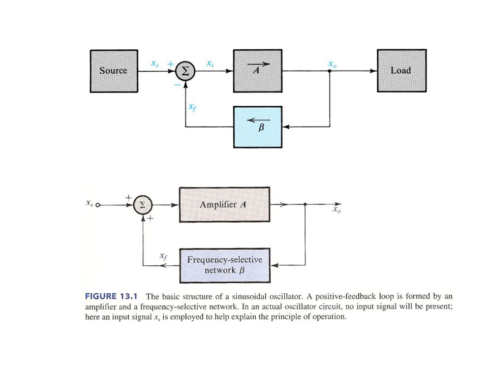
The oscillator feeback loop

4
The oscillation criterion

5
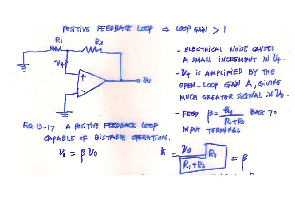
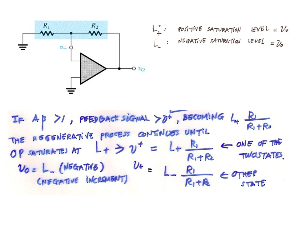
13.4.1 The Feedback Loop . Fig.13.17 A positive – feedback loop capable of bistable operation

8
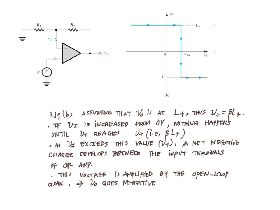
13. 4. 2 Transfer Characteristics of the Bistable Circuit. Fig. 13
Transfer Characteristics of the Bistable Circuit . Fig (a) The bistable circuit of Fig with the negative input terminal of the op amp disconnected from ground and connected to an input signal vI ; (b) The transfer characteristic of (a) for increasing vI ; (c) The transfer characteristic for decreasing vI and (d) The complete transfer characteristics
 The bistable circuit of Fig with the negative input terminal of the op amp disconnected from ground and connected to an input signal vI ; (b) The transfer characteristic of (a) for increasing vI ; (c) The transfer characteristic for decreasing vI and (d) The complete transfer characteristics.")
16
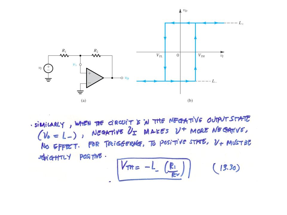
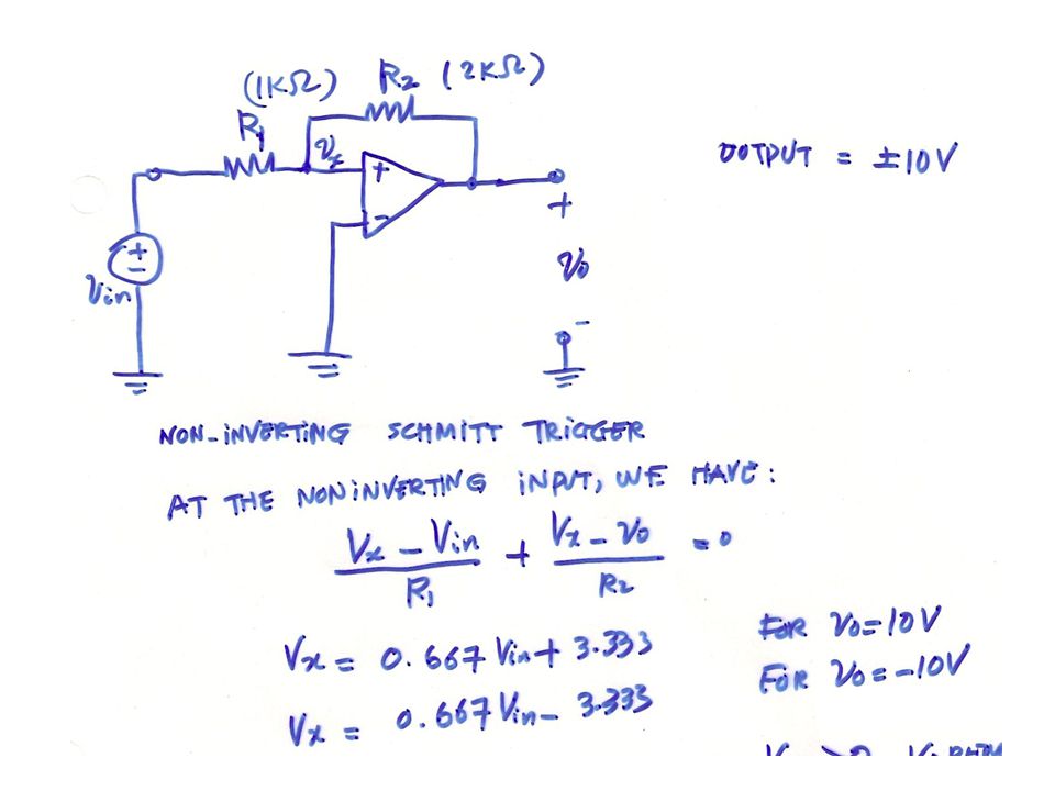
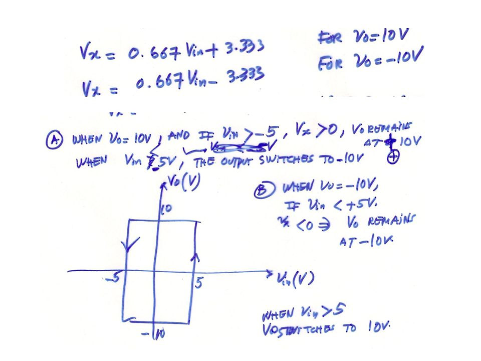
A Bistable Circuit with Noninverting Transfer Charactewristics . Fig (a) A bistable circuit derived from the positive – feedback loop of Fig by applying vI through RI . (b) The trasnfer characteristic of the circuit in (a) is noninverting
 A bistable circuit derived from the positive – feedback loop of Fig by applying vI through RI . (b) The trasnfer characteristic of the circuit in (a) is noninverting.")
17
13-4-5 A bistable circuit with noninverting transfer characteristics

19
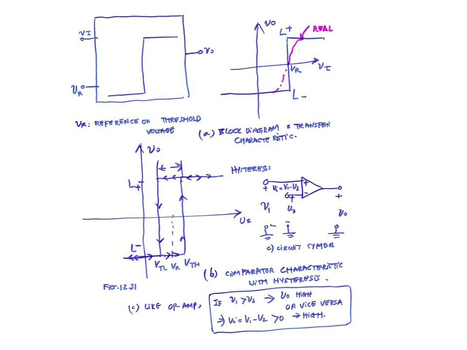
13. 4. 6 Application of the Bistable Circuit as a Comparator. Fig. 13
Application of the Bistable Circuit as a Comparator . Fig (a) Block diagram representation and transfer characteristic for comparator having a reference , or threshold, voltage vR . (b) Comparator characteristic with hysteresis .
 Block diagram representation and transfer characteristic for comparator having a reference , or threshold, voltage vR . (b) Comparator characteristic with hysteresis .")
24
13-5 Generation of square and triangular waveforms using astable multivibrators

25
Fig (a) Connecting a bistable multivibrator with inverting transfer characteristics in a feedback loop with an RC circuit
 Connecting a bistable multivibrator with inverting transfer characteristics in a feedback loop with an RC circuit.")
26
Fig (continued) (b) the circcuit obtained when the bistable multivibrator is implemented with the circuit in Fig (a) . (c) Waveforms at various nodes of the circuit in (b) . This circuit is called an astable multivibrator .
 (b) the circcuit obtained when the bistable multivibrator is implemented with the circuit in Fig (a) . (c) Waveforms at various nodes of the circuit in (b) . This circuit is called an astable multivibrator ..")
32
13. 7 Integrated Circuit Timers. Fig. 13
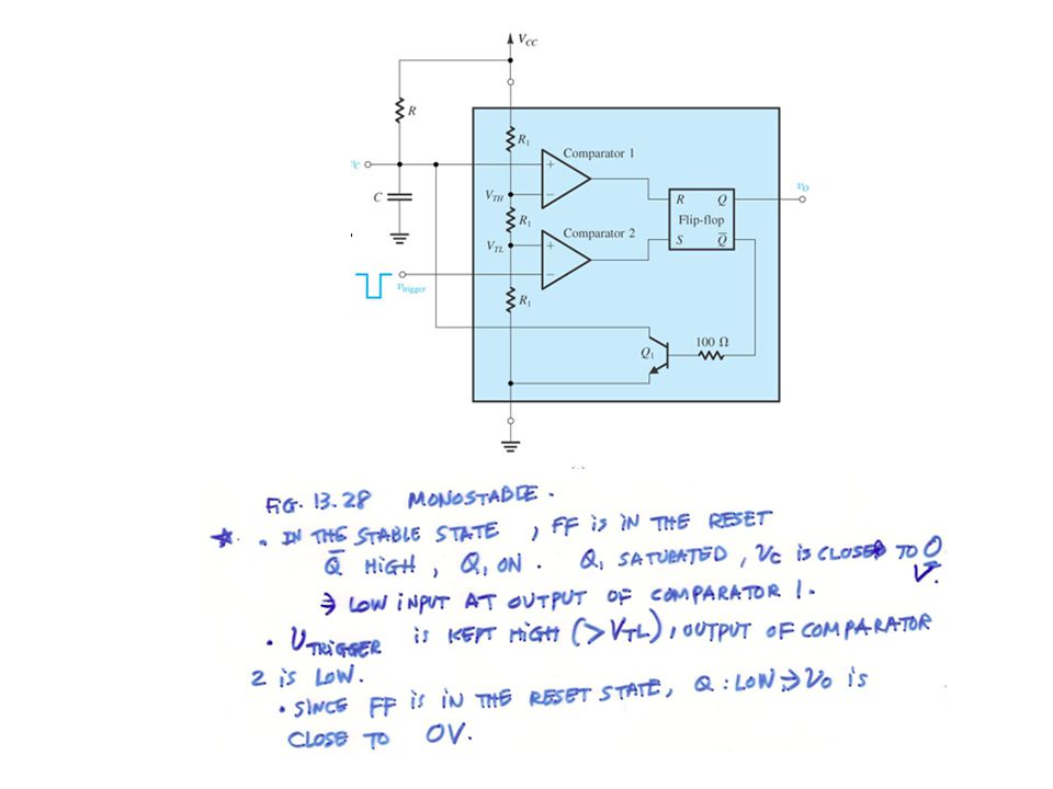
13.7 Integrated Circuit Timers . Fig A block diagram representation of the internal circuit of the 555 integrated- circuit timer .

34
13. 7. 2 Implementing a Monostable Multivibrator Using the 555 IC. Fig
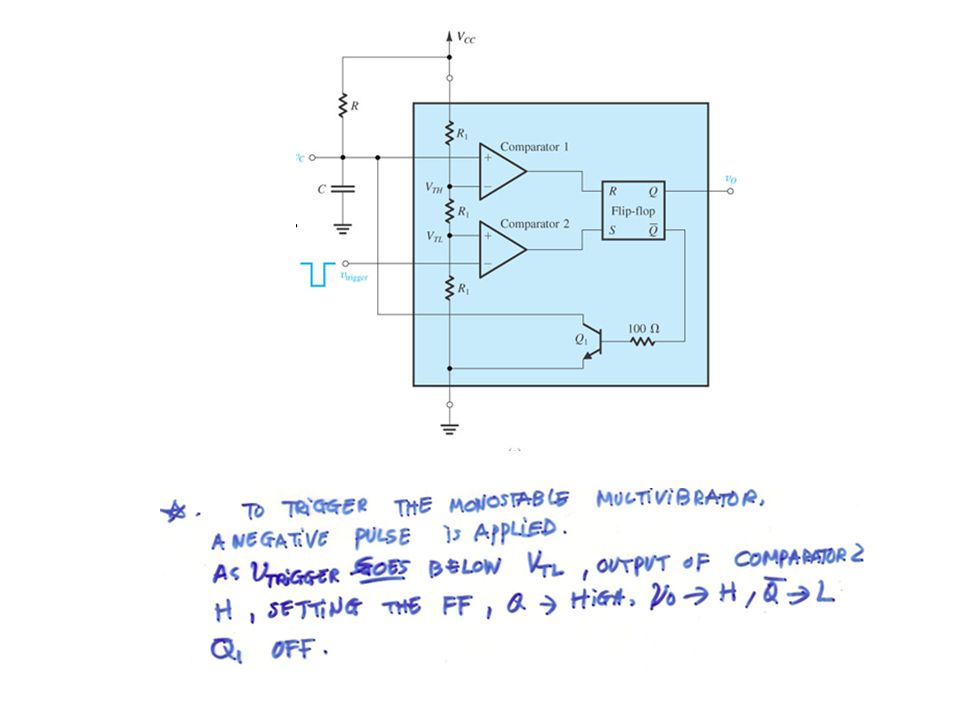
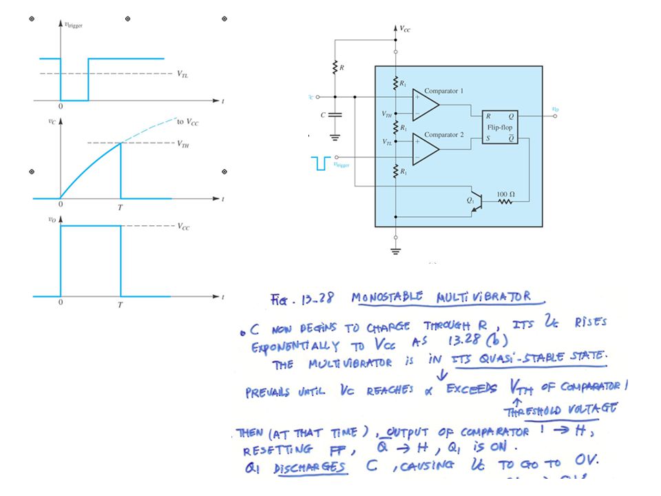
Implementing a Monostable Multivibrator Using the 555 IC . Fig (a) The 555 timer connected to implement a monostable multivibrator . (b) Waveforms of the circuit in
 The 555 timer connected to implement a monostable multivibrator . (b) Waveforms of the circuit in.")
40
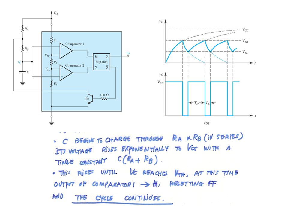
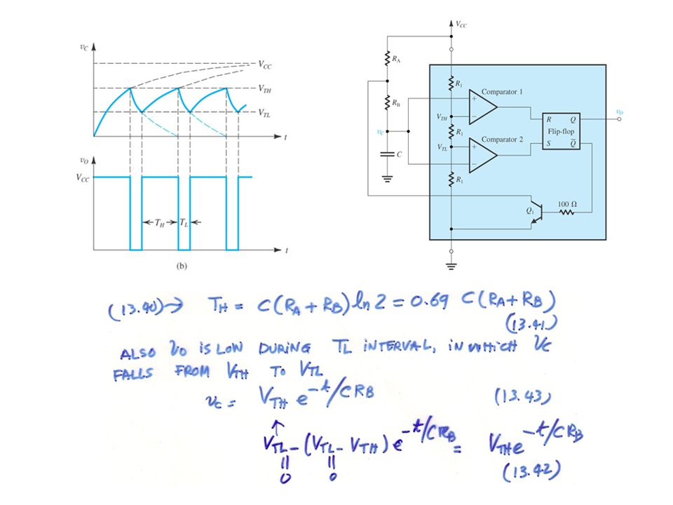
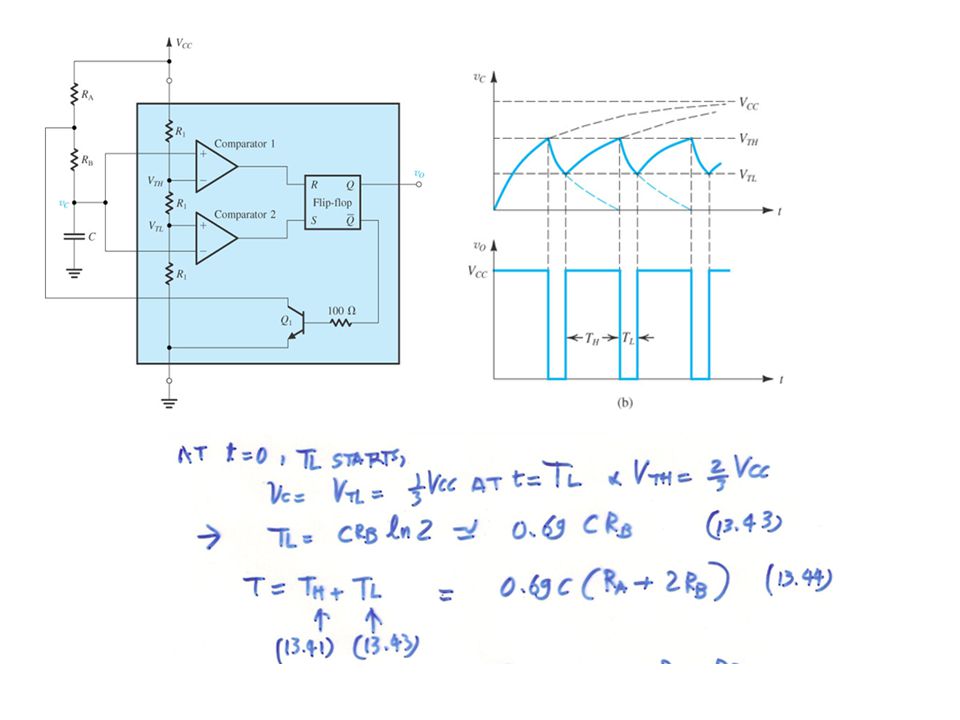
13. 7. 3 An astable multivibrator using the 555 IC. Fig. 13
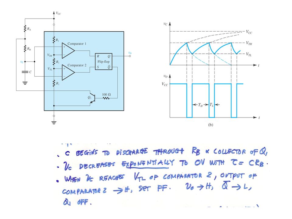
An astable multivibrator using the 555 IC . Fig (A) The 555 timer connected to implement an astable multivibrator . (b) Waveforms of the circuit in (a) .
 The 555 timer connected to implement an astable multivibrator . (b) Waveforms of the circuit in (a) .")
Similar presentations


 for applications.>")


 A popular limiter circuit. (b) Transfer characteristic of the limiter circuit; L - and L + are given by Eqs. (12.8) and (12.9), respectively.>")
>")


>")

