Download presentation
Presentation is loading. Please wait.

1
Nomenclature Usually, it is sufficient to know the energy En(k) curves - the dispersion relations - along the major directions. Directions are chosen that lead aong special symmetry points. These points are labeled according to the following rules: Direction along BZ Points (and lines) inside the Brillouin zone are denoted with Greek letters. Points on the surface of the Brillouin zone with Roman letters. The center of the Wigner-Seitz cell is always denoted by a G Energy or Frequency
 inside the Brillouin zone are denoted with Greek letters. Points on the surface of the Brillouin zone with Roman letters. The center of the Wigner-Seitz cell is always denoted by a G. Energy or Frequency.")
2
Brillouin Zones in 3D fcc bcc hcp The BZ reflects lattice symmetry
Note: bcc lattice in reciprocal space is a fcc lattice Print out one of these to show? (Probably should keep white tab with labels on the outside) hcp Note: fcc lattice in reciprocal space is a bcc lattice The BZ reflects lattice symmetry Construction leads to primitive unit cell in rec. space
 hcp. Note: fcc lattice in reciprocal space is a bcc lattice. The BZ reflects lattice symmetry. Construction leads to primitive unit cell in rec. space.")
3
Brillouin Zone of Silicon
Symbol Description Γ Center of the Brillouin zone Simple Cubic M Center of an edge R Corner point X Center of a face FCC K Middle of an edge joining two hexagonal faces L Center of a hexagonal face C6 U Middle of an edge joining a hexagonal and a square face W Center of a square face C4 BCC H Corner point joining 4 edges N P Corner point joining 3 edges What kind of crystal structure is Si? Why do I say semiconductors? Metals are most freely so barely effected. Insulators don’t really conduct so don’t move around. Points of symmetry on the BZ are important (e.g. determining bandstructure). Electrons in semiconductors are perturbed by the potential of the crystal, which varies across unit cell.
. Electrons in semiconductors are perturbed by the potential of the crystal, which varies across unit cell.")
4
Learning Objectives for Diffraction
After our diffraction class you should be able to: Explain why diffraction occurs Utilize Bragg’s law to determine angles of diffraction Discuss some different diffraction techniques (Next time) Determine the lattice type and lattice parameters of a material given an XRD pattern and the x-ray energy Alternative reference: Ch. 2 Kittel
 Determine the lattice type and lattice parameters of a material given an XRD pattern and the x-ray energy. Alternative reference: Ch. 2 Kittel.")
5
Continuum limit: Where the wavelength is bigger than the spacing between atoms. Otherwise diffraction effects dominate. Why might you want to think about optical properties? There are at least two reasons. One is that you can make use of known optical materials to design and build devices to manipulate light: mirrors, lenses, filters, polarizers, and a host of others. The second is that you can measure the optical response of a new material and obtain a wealth of information about the low energy excitations in the solid. With the use of your own eyes, you could see that solids have a wide range of optical properties. Silver is a lustrous metal, with a high reflectance over the whole visible range. Silicon is a crystalline semiconductor and the basis of modern electronics. With the surface oxide freshly etched off, silicon is also rather reflective, although not as good a mirror as silver. ∗ Salt (sodium chloride) is a transparent ionic insulator, is necessary for life, and makes up about 3.5% (by weight) of seawater. A crystal of salt is transparent over the entire visible spectrum; because the refractive index is about 1.5, the reflectance is about 4%. If you had ultraviolet eyes, you would see these materials differently. Silver would be a poor reflector, with at most 20% reflectance and trailing off to zero at the shortest wavelengths. In contrast, the reflectance of silicon would be better than in the visible, reaching up to 75%. Sodium chloride would be opaque over much of the spectrum, with a reflectance a bit higher than in the visible. Those with infrared eyes would also see things differently from visible or uv-sensitive individuals. Silver would have a reflectance above 99%. Silicon would appear opaque at the shortest infrared wavelengths but would then become transparent, so that you could see through even meter-thick crystals.† Sodium chloride remains transparent over much of the infrared
 is a transparent ionic insulator, is necessary for life, and makes up about 3.5% (by weight) of seawater. A crystal of salt is transparent over the entire visible spectrum; because the refractive index is about 1.5, the reflectance is about 4%. If you had ultraviolet eyes, you would see these materials differently. Silver would be a. poor reflector, with at most 20% reflectance and trailing off to zero at the shortest wavelengths. In contrast, the reflectance of silicon would be better than in the visible, reaching up. to 75%. Sodium chloride would be opaque over much of the spectrum, with a reflectance a. bit higher than in the visible. Those with infrared eyes would also see things differently from. visible or uv-sensitive individuals. Silver would have a reflectance above 99%. Silicon would. appear opaque at the shortest infrared wavelengths but would then become transparent, so. that you could see through even meter-thick crystals.† Sodium chloride remains transparent. over much of the infrared.")
6
Application of XRD XRD is a nondestructive and cheap technique. Some of the uses of x-ray diffraction are: Determination of the structure of crystalline materials Measurement of strain and small grain size Determination of the orientation of single crystals Measurement of layer thickness Differentiation between crystalline and amorphous materials Determination of electron distribution within the atoms, and throughout the unit cell Determination of the texture of polygrained materials Need to get rid of old duplicates following this.

7
DIFFRACTION Diffraction is a wave phenomenon in which the apparent bending and spreading of waves when they meet an obstruction is measured. Diffraction occurs with electromagnetic waves, such as light and radio waves, and also in sound waves and water waves. X-ray diffraction is optimally sensitive to the periodic nature of the solid’s atomic structure.

8
When X-rays interact with atoms, you get scattering
Scattering is the emission of X-rays of the same frequency/energy as the incident X-rays in all directions (but with much lower intensity) Similar to the double slit experiment, this scattering will sometimes be constructive Second order process due to phase ambiguity, doesn’t matter if initial photon is absorbed before emitted photon. See from Fermi’s golden rule (Ch.4 in the book).
 Similar to the double slit experiment, this scattering will sometimes be constructive. Second order process due to phase ambiguity, doesn’t matter if initial photon is absorbed before emitted photon. See from Fermi’s golden rule (Ch.4 in the book).")
9
Will look at this again shortly
Incident beam Will look at this again shortly Second order Note diameter of smallest circle is one wavelength. Third circular is two wavelengths. The light must be incident over some time to create the wavefronts shown. Zeroth Order

10
Physical Model for X-ray Scattering
Consider a plane wave scattering on an atom. Atom What isn’t r squared? We are looking at si, not intensity.

11
Diffraction Theory Generic incoming radiation amplitude is:
To calculate amplitude of scattered waves at detector position, sum over contributions of all scattering centers Pi with scattering amplitude (form factor) f: Pi ri ko R R’-ri R’ source R, R’ >> ri Generic for any point in the sample. (ignoring the time dependence, will disappear when we square it) If R is much greater than ri, then can pull out the exponents involving R from both si incident and si outgoing Detector The intensity that is measured (can’t measure amplitude) is Scattering vector The book calls K, but G is another common notation.
 f: Pi. ri. ko. R. R’-ri. R’ source. R, R’ >> ri. Generic for any point in the sample. (ignoring the time dependence, will disappear when we square it) If R is much greater than ri, then can pull out the exponents involving R from both si incident and si outgoing. Detector. The intensity that is measured (can’t measure amplitude) is. Scattering vector. The book calls K, but G is another common notation.")
12
Diffraction Theory k’ K=k’-ko ko
Pi ri ko ko R R’-ri R’ source Generic for any point in the sample. (ignoring the time dependence, will disappear when we square it) If R is much greater than ri, then can pull out the exponents involving R from both si incident and si outgoing Detector The intensity that is measured (can’t measure amplitude) is Scattering vector The book calls K, but G is another common notation.
 If R is much greater than ri, then can pull out the exponents involving R from both si incident and si outgoing. Detector. The intensity that is measured (can’t measure amplitude) is. Scattering vector. The book calls K, but G is another common notation.")
13
The Bottom Line If you do a whole bunch of math you can prove that the peaks only occur when (a1, a2, a3=lattice vectors): n1, n2, n3 integers Compare these relations to the properties of reciprocal lattice vectors:

14
The Laue Condition Replacing n1 n2 n3 with the familiar h k l, we see that these three conditions are equivalently expressed as: The Laue condition (Max von Laue, 1911) So, the condition for nonzero intensity is that the scattering vector K is a translation vector of the reciprocal lattice. n1, n2, n3 integers
 So, the condition for nonzero intensity is that the scattering vector K is a translation vector of the reciprocal lattice. n1, n2, n3 integers.")
15
Show vector subtraction on the board
From Laue to Bragg The magnitude of the scattering vector K depends on the angle between the incident wave vector and the scattered wave vector: Show vector subtraction on the board Notice this angle is 2! Elastic scattering requires: Draw vector k-ko on the board to illustrate correct direction of K. Elastic scattering requires no energy lose, so k’s magnitude is the same Use right triangles to show 2ksin theta You can use a similar argument to show how d and lambda are related So from the wave vector triangle and the Laue condition we see: Leaving Bragg’s law: If the Bragg condition is not met, the incoming wave just moves through the lattice and emerges on the other side of the crystal (neglecting absorption)
")
16
Bragg Equation where, d is the spacing of the planes and n is the order of diffraction. Bragg reflection can only occur for wavelength This is why we cannot use visible light. No diffraction occurs when the above condition is not satisfied.

17
X-ray Diffraction Typical interatomic distances in solid are of the order of 0.4 nm. Upon substituting this value for the wavelength into the energy equation, we find that E is of the order of 3000 eV, which is a typical x-ray energy. Thus x-ray diffraction of crystals is a standard diffraction probe.

18
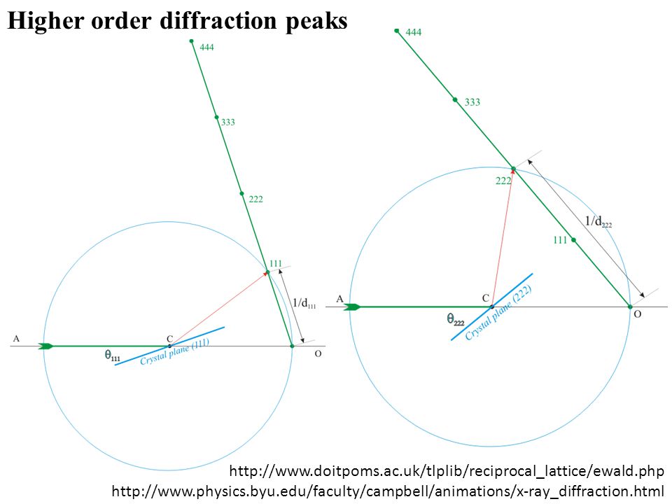
Bragg Equation: The diffracted beams (reflections) from any set of lattice planes can only occur at particular angles pradicted by the Bragg law. When atoms are specific phases apart. Otherwise they destructively interfere over the many layers of the crystal. Also shows why higher order diffraction occurs (just off by a multiple of the wavelength). Above are 1st, 2nd, 3rd and 4th order “reflections” from the (111) face of NaCl. Orders of reflections are given as 111, 222, 333, 444, etc. (without parentheses!)
. Above are 1st, 2nd, 3rd and 4th order reflections from the (111) face of NaCl. Orders of reflections are given as 111, 222, 333, 444, etc. (without parentheses!)")
19
A single crystal specimen in a Bragg-Brentano diffractometer (θin=θout) would produce only one family of peaks in the diffraction pattern. 2q The (110) planes would diffract at 29.3 °2q; however, they are not properly aligned to produce a diffraction peak (the perpendicular to those planes does not bisect the incident and diffracted beams). Only background is observed. At 20.6 °2q, Bragg’s law fulfilled for the (100) planes, producing a diffraction peak. The (200) planes are parallel to the (100) planes. Therefore, they also diffract for this crystal. Since d200 is ½ d100, they appear at 42 °2q.
 planes would diffract at 29.3 °2q; however, they are not properly aligned to produce a diffraction peak (the perpendicular to those planes does not bisect the incident and diffracted beams). Only background is observed. At 20.6 °2q, Bragg’s law fulfilled for the (100) planes, producing a diffraction peak. The (200) planes are parallel to the (100) planes. Therefore, they also diffract for this crystal. Since d200 is ½ d100, they appear at 42 °2q.")
20
THE EWALD SPHERE O 2 2/ Consider an arbitrary sphere
passing through the reciprocal lattice, with the crystal arranged in the center of the sphere. We specify two conditions: the sphere radius is 2 / - the inverse wavelength of X-ray radiation the origin of the reciprocal lattice lies on the surface of the sphere X-rays are ON diffracted ray 2 O 2/ The diffraction spot will be observed when a reciprocal lattice point crosses the Ewald sphere

21
The Ewald Sphere Only a few angles A sphere of radius k
Surface intersects a point in reciprocal space and its origin is at the tip of the incident wavevector. Sphere can be moved in reciprocal lattice space arbitrarily. Any points which intersect the surface of the sphere indicate where diffraction peaks will be observed if the structure factor is nonzero (later). Only a few angles The Ewald Sphere touches the reciprocal lattice (for point 41) Bragg’s equation is satisfied for 41
. Only a few angles. The Ewald Sphere touches the reciprocal lattice (for point 41) Bragg’s equation is satisfied for 41.")
22
1. Longitudinal or θ-2θ scan
Sample moves as θ, Detector follows as 2θ k0 k’

23
1. Longitudinal or θ-2θ scan
Sample moves on θ, Detector follows on 2θ K k0 k’ Reciprocal lattice rotates by θ during scan

24
1. Longitudinal or θ-2θ scan
Sample moves on θ, Detector follows on 2θ K k0 k’ 2q

25
1. Longitudinal or θ-2θ scan
Sample moves on θ, Detector follows on 2θ K k0 k’ 2q

26
1. Longitudinal or θ-2θ scan
Sample moves on θ, Detector follows on 2θ K k0 2q k’

27
1. Longitudinal or θ-2θ scan
Sample moves on θ, Detector follows on 2θ K k0 2q k’

28
1. Longitudinal or θ-2θ scan
Sample moves on θ, Detector follows on 2θ k’ K k0 2q Provides information about relative arrangements, angles, and spacings between crystal planes.

29
Higher order diffraction peaks
30
3 COMMON X-RAY DIFFRACTION METHODS
Laue Rotating Crystal Powder Orientation Single Crystal Polychromatic Beam Fixed Angle Lattice constant Single Crystal Monochromatic Beam Variable Angle Lattice Parameters Polycrystal/Powder Monochromatic Beam Variable Angle

31
Back-reflection vs. Transmission Laue Methods
In the back-reflection method, the film is placed between the x-ray source and the crystal. The beams which are diffracted backward are recorded. Which is this? X-rays have wide wavelength range (called white beam). Single Crystal X-Ray Film Single Crystal Film X-Ray The diffraction spots generally lay on: an ellipse a hyperbola
. Single. Crystal. X-Ray. Film. Single. Crystal. Film. X-Ray. The diffraction spots generally lay on: an ellipse. a hyperbola.")
32
LAUE METHOD The diffracted beams form arrays of spots, that lie on curves on the film. Each set of planes in the crystal picks out and diffracts a particular wavelength from the white radiation that satisfies the Bragg law for the values of d and θ involved. Laue on one of our thin films.

33
Great for symmetry and orientation determination
Laue Pattern The symmetry of the spot pattern reflects the symmetry of the crystal when viewed along the direction of the incident beam. Great for symmetry and orientation determination It’s a bit of an art to interpret these things. Takes some practice.

34
Crystal structure determination by Laue method?
Although the Laue method can be used, several wavelengths can reflect in different orders from the same set of planes, making structure determination difficult (use when structure known for orientation or strain). Rotating crystal method overcomes this problem. How? You would interpret from the intensity of the spots, but if multiple spots are at the same location, that’s a problem. Materials scientists typically already know the crystal structure for a material they’ve worked on a lot and then this method can be used to understand orientation or strain tensors.
. Rotating crystal method overcomes this problem. How You would interpret from the intensity of the spots, but if multiple spots are at the same location, that’s a problem. Materials scientists typically already know the crystal structure for a material they’ve worked on a lot and then this method can be used to understand orientation or strain tensors.")
35
ROTATING CRYSTAL METHOD
A single crystal is mounted with a rotation axis perpendicular to a monochromatic x-ray beam. A cylindrical film is placed around it and the crystal is rotated. Sets of lattice planes will at some point make the correct Bragg angle, and at that point a diffracted beam will be formed.

36
Rotating Crystal Method
Reflected beams are located on imaginary cones. By recording the diffraction patterns (both angles and intensities), one can determine the shape and size of unit cell as well as arrangement of atoms inside the cell. Requires various orientations measured and you may not know where those orientations are, so hard if that is the case. Film
, one can determine the shape and size of unit cell as well as arrangement of atoms inside the cell. Requires various orientations measured and you may not know where those orientations are, so hard if that is the case. Film.")
37
THE POWDER METHOD Least crystal information needed ahead of time
If a powder is used, instead of a single crystal, then there is no need to rotate the sample, because there will always be some crystals at an orientation for which diffraction is permitted. A monochromatic X-ray beam is incident on a powdered or polycrystalline sample. Common method if you don’t know much about your material (or if you already have it in powder form).
.")
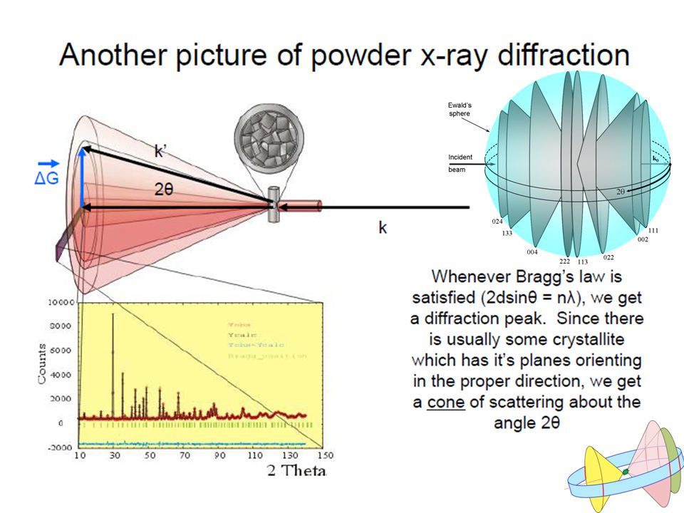
38
The Powder Method A sample of some hundreds of crystals (i.e. a powdered sample) show that the diffracted beams form continuous cones. A circle of film is used to record the diffraction pattern as shown. Each cone intersects the film giving diffraction arcs. If a monochromatic x-ray beam is directed at a single crystal, then only one or two diffracted beams may result. If the sample consists of some tens of randomly orientated single crystals, the diffracted beams are seen to lie on the surface of several cones. The cones may point both forwards and backwards.

39
Powder diffraction film
When the film is removed from the camera, flattened and processed, it shows the diffraction lines and the holes for the incident and transmitted beams.

41
Useful for Phase Identification
The diffraction pattern for every phase is as unique as your fingerprint Phases with the same element composition can have drastically different diffraction patterns. Use the position and relative intensity of a series of peaks to match experimental data to the reference patterns in the database

42
Databases such as the Powder Diffraction File (PDF) contain dI lists for thousands of crystalline phases. The PDF contains over 200,000 diffraction patterns. Modern computer programs can help you determine what phases are present in your sample by quickly comparing your diffraction data to all of the patterns in the database.

43
Quantitative Phase Analysis
With high quality data, you can determine how much of each phase is present The ratio of peak intensities varies linearly as a function of weight fractions for any two phases in a mixture RIR method is fast and gives semi-quantitative results Whole pattern fitting/Rietveld refinement is a more accurate but more complicated analysis Reference Intensity Ratio Method RIR method: need to know the constant of proportionality

44
Applications of Powder Diffractometry
phase analysis (comparison to known patterns) unit cell determination (dhkl′s depend on lattice parameters) particle size estimation (line width) crystal structure determination (line intensities and profiles)
 unit cell determination (dhkl′s depend on lattice parameters) particle size estimation (line width) crystal structure determination (line intensities and profiles)")
45
XRD: “Rocking” Curve Scan
Sample normal “Rock” Sample Vary ORIENTATION of K relative to sample normal while maintaining its magnitude. How? “Rock” sample over a very small angular range. Resulting data of Intensity vs. Omega (w, sample angle) shows detailed structure of diffraction peak being investigated. Can inform about quality of sample. Draw a flat line versus a line with small tilts in either direction
 shows detailed structure of diffraction peak being investigated. Can inform about quality of sample. Draw a flat line versus a line with small tilts in either direction.")
46
XRD: Rocking Curve Example
GaN Thin Film Compare to literature to see how good (some materials naturally easier than others) (002) Reflection 16000 Intensity (Counts/s) 8000 Generally limited by quality of substrate Could give a whole course on diffraction, but lots more to cover I’m not talking politics, I just think having Obama cropped in the picture is funny. 16.995 17.195 17.395 17.595 17.795 Omega (deg) Rocking curve of single crystal GaN around (002) diffraction peak showing its detailed structure.
 (002) Reflection Intensity (Counts/s) Generally limited by quality of substrate. Could give a whole course on diffraction, but lots more to cover. I’m not talking politics, I just think having Obama cropped in the picture is funny Omega (deg) Rocking curve of single crystal GaN around (002) diffraction peak showing its detailed structure.")
47
X-Ray Reflectivity (XRR)
A glancing, but varying, incident angle, combined with a matching detector angle collects the X rays reflected from the samples surface Interference fringes in the reflected signal can be used to determine: thickness of thin film layers density and composition of thin film layers roughness of films and interfaces

48
X-ray reflectivity measurement
Calculation of the electron density, thickness and interface roughness for each particular layer r t [Å] s [Å] Edge of TER Kiessig oscillations (fringes) Mo Mo Mo W Si The surface must be smooth (mirror-like)
 Mo. Mo. Mo. W. Si. The surface must be smooth (mirror-like)")
49
Lots of extra slides There is a lot of useful information on diffraction. Following are some related slides that I have used or considered using in the past. A whole course could be tough focusing on diffraction so I can’t cover everything here.

50
XRD: Reciprocal-Space Map
GaN(002) AlN /2 Vary Orientation and Magnitude of k. Diffraction-Space map of GaN film on AlN buffer shows peaks of each film.
 AlN. /2 Vary Orientation and Magnitude of k. Diffraction-Space map of GaN film on AlN buffer shows peaks of each film.")
51
Preferred Orientation (texture)
Diffracting crystallites Preferred Orientation (texture) Preferred orientation of crystallites can create a systematic variation in diffraction peak intensities can qualitatively analyze using a 1D diffraction pattern a pole figure maps the intensity of a single peak as a function of tilt and rotation of the sample this can be used to quantify the texture (111) (311) (200) (220) (222) (400) 40 50 60 70 80 90 100 Two-Theta (deg) x10 3 2.0 4.0 6.0 8.0 10.0 Intensity(Counts) > Gold - Au
 Preferred orientation of crystallites can create a systematic variation in diffraction peak intensities. can qualitatively analyze using a 1D diffraction pattern. a pole figure maps the intensity of a single peak as a function of tilt and rotation of the sample. this can be used to quantify the texture. (111) (311) (200) (220) (222) (400) Two-Theta (deg) x Intensity(Counts) > Gold - Au.")
52
The X-ray Shutter is the most important safety device on a diffractometer
X-rays exit the tube through X-ray transparent Be windows. X-Ray safety shutters contain the beam so that you may work in the diffractometer without being exposed to the X-rays. Being aware of the status of the shutters is the most important factor in working safely with X rays.

53
interact with electron interact with electron
Diffraction Methods Any particle will scatter and create diffraction pattern Beams are selected by experimentalists depending on sensitivity X-rays not sensitive to low Z elements, but neutrons are Electrons sensitive to surface structure if energy is low Atoms (e.g., helium) sensitive to surface only For inelastic scattering, momentum conservation is important X-Ray Neutron Electron λ = 1A° E ~ 104 eV interact with electron Penetrating λ = 1A° E ~ 0.08 eV interact with nuclei Highly Penetrating λ = 2A° E ~ 150 eV interact with electron Less Penetrating
 sensitive to surface only. For inelastic scattering, momentum conservation is important. X-Ray. Neutron. Electron. λ = 1A° E ~ 104 eV. interact with electron. Penetrating. λ = 1A° E ~ 0.08 eV. interact with nuclei. Highly Penetrating. λ = 2A° E ~ 150 eV. interact with electron. Less Penetrating.")
54
Electron Diffraction (Covered in Chapter 18)
If low electron energies are used, the penetration depth will be very small (only about 50 A°), and the beam will be reflected from the surface. Consequently, electron diffraction is a useful technique for surface structure studies. Electrons are scattered strongly in air, so diffraction experiment must be carried out in a high vacuum. This brings complication and it is expensive as well.
, and the beam will be reflected from the surface. Consequently, electron diffraction is a useful technique for surface structure studies. Electrons are scattered strongly in air, so diffraction experiment must be carried out in a high vacuum. This brings complication and it is expensive as well.")
55
Electron Diffraction Electron diffraction has also been used in the analysis of crystal structure. The electron, like the neutron, possesses wave properties; Electrons are charged particles and interact strongly with all atoms. So electrons with an energy of a few eV would be completely absorbed by the specimen. In order that an electron beam can penetrate into a specimen , it necessitas a beam of very high energy (50 keV to 1MeV) as well as the specimen must be thin ( nm)
 as well as the specimen must be thin ( nm)")
Similar presentations


>")

 We also looked at internal ordering of atoms in 3-D structure (230 space.>")


