Download presentation
Presentation is loading. Please wait.

1
Electrical Stimulation of the Neuromuscular system

2
Outline Introduction Neuro-muscular junction, myelin sheet
Examples of neuromuscular prostheses Upper extremity Lower extremity Bladder stimulation Derivatives () and cross, dot products. Mathematical formulation of the effect of current stimulation from electrode immersed in conductive media.
 and cross, dot products. Mathematical formulation of the effect of current stimulation from electrode immersed in conductive media.")
3
The neuromuscular junction
(1min) (3min, McGrawHill book)
 v=YnVY4Waimwg (3min, McGrawHill book)")
4
Neurons, revisited

5
Membrane potential

6
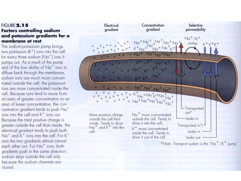
Membrane potential: how does it come about?
Charge in each compartment is balanced Outside the cell, sum of anions = sum of cations [Na+] + 2[Ca++] + [K+] = [Cl-] Inside the cell, sum of anions = sum of cations [Na+] + 2[Ca++] + [K+] = [Cl-] + [A-] A- are other anions, which are mostly proteins Anions are impermeant to the membrane

8
Identifying parts of a stained neuron:
How does a spike happen?

9
Ion channel states

10
Ion channels, Agonists, antagonists.

11
Cable theory, passive conduction.

12
Neurons, Myelin sheath, Synapses

13
Chemical synapses

14
Chemical and electrical synapses, voltage clamp

15
Passive and active responses, Ion channel states

16
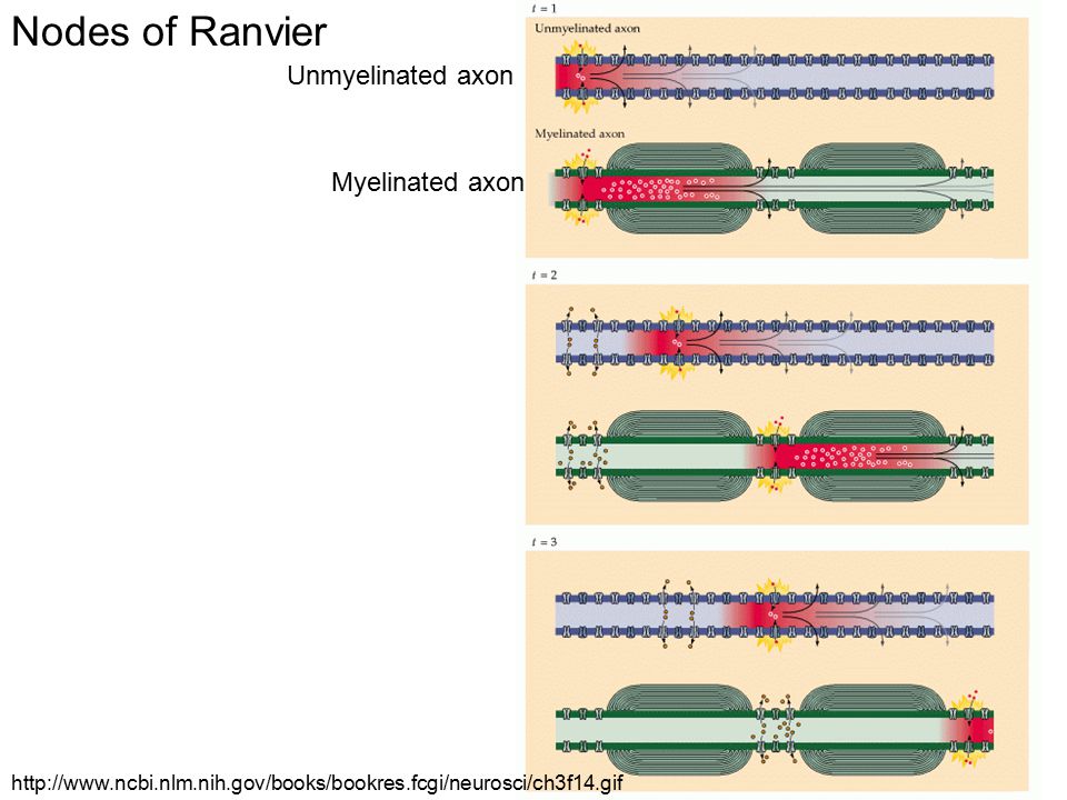
Saltatory conduction

17
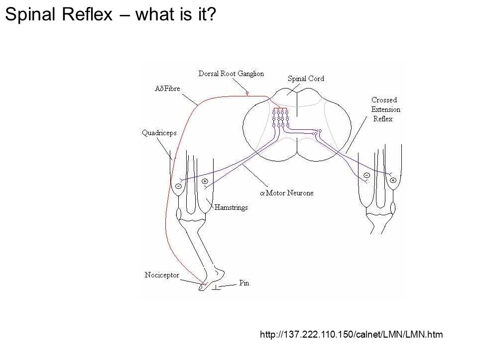
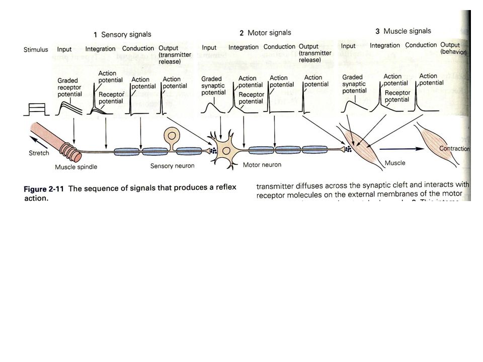
Myotactic reflex A simple reflex circuit, the knee-jerk response (more formally, the myotatic reflex), illustrates several points about the functional organization of neural circuits. Stimulation of peripheral sensors (a muscle stretch receptor in this case) initiates receptor potentials that trigger action potentials that travel centrally along the afferent axons of the sensory neurons. This information stimulates spinal motor neurons by means of synaptic contacts. The action potentials triggered by the synaptic potential in motor neurons travel peripherally in efferent axons, giving rise to muscle contraction and a behavioral response. One of the purposes of this particular reflex is to help maintain an upright posture in the face of unexpected changes.
, illustrates several points about the functional organization of neural circuits. Stimulation of peripheral sensors (a muscle stretch receptor in this case) initiates receptor potentials that trigger action potentials that travel centrally along the afferent axons of the sensory neurons. This information stimulates spinal motor neurons by means of synaptic contacts. The action potentials triggered by the synaptic potential in motor neurons travel peripherally in efferent axons, giving rise to muscle contraction and a behavioral response. One of the purposes of this particular reflex is to help maintain an upright posture in the face of unexpected changes.")
18
Intracellular responses during the myotactic reflex
Intracellularly recorded responses underlying the myotatic reflex. (A) Action potential measured in a sensory neuron. (B) Postsynaptic triggering potential recorded in an extensor motor neuron. (C) Postsynaptic triggering potential in an interneuron. (D) Postsynaptic inhibitory potential in a flexor motor neuron. Such intracellular recordings are the basis for understanding the cellular mechanisms of action potential generation, and the sensory receptor and synaptic potentials that trigger these conducted signals.
 Action potential measured in a sensory neuron. (B) Postsynaptic triggering potential recorded in an extensor motor neuron. (C) Postsynaptic triggering potential in an interneuron. (D) Postsynaptic inhibitory potential in a flexor motor neuron. Such intracellular recordings are the basis for understanding the cellular mechanisms of action potential generation, and the sensory receptor and synaptic potentials that trigger these conducted signals.")
19
Reflex as result of sensory neuron stimulation

21
References – previous 18 slides.
Action potential animation: Books available online: Neuroscience book where I took most figures from:

22
Vertebrate motoneuron

23
Myelin Tight wrapping of cell membrane around axon
Cytoplasm of glial cell is gradually squeezed out as cell wraps around Result is concentric layers of closely apposed membrane Acts as electrical insulator Huge increase in speed of action potential transmission

24
Myelinated axons, nodes of Ranvier
Myelin sheath (transversal section) Axon (transversal section)
 Axon (transversal section)")
25
Unmyelinated axons

26
Myelin is produced by glia
Oligodendrocytes in CNS Schwann cells in PNS vv.carleton.ca/~neil/neural/neuron-a.html

27
Nodes of Ranvier Unmyelinated axon Myelinated axon
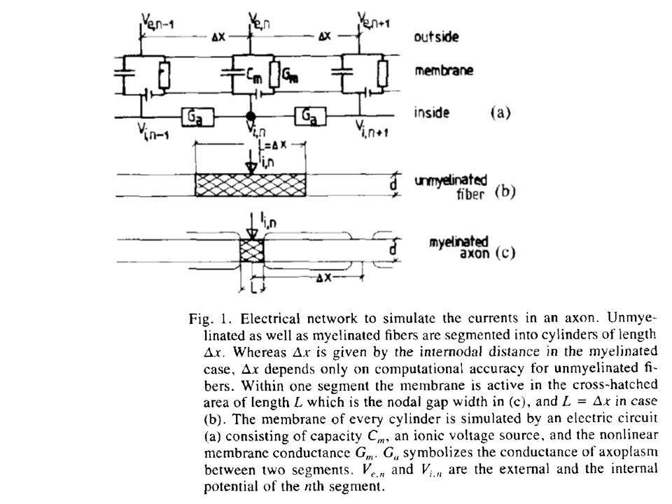
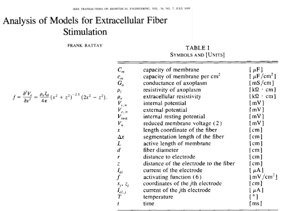
28
Saltatory conduction (Ranvier nodes), and second derivative of the extracellular potential.
, and second derivative of the extracellular potential.")
29
Electrode-tissue interface
Constant current x constant voltage stimulation Tissue damage: Passive: presence of foreign object (mechanical) Active: passage of current (electrochemical)
 Active: passage of current (electrochemical)")
30
Damage to biological tissue
Passive: vascular or neural How to overcome this? Change electrode size, tip geometry, substrate, anchoring Active: primary (reaction products from electrochemistry); secondary (physiological changes associated with neural excitation.
; secondary (physiological changes associated with neural excitation.")
31
Effect of waveform Strength-duration curve (obtained empirically):
PW= pulsewidth Ith=threshold current Irh = rheobase current, minimum current amplitude if PW→∞. Tch = chronaxie time PW to excite neuron with 2Irh. Ith= Irh+(IthTch/PW)
")
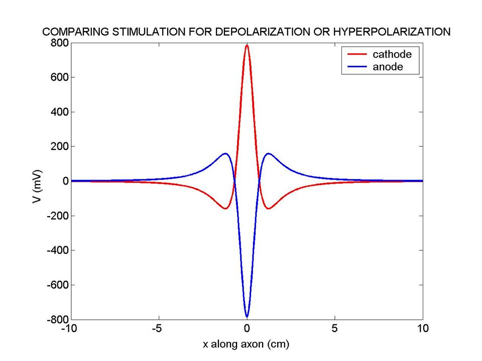
32
Anodic vs cathodic stimulation

33
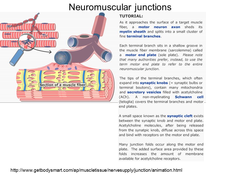
Neuromuscular junctions
34
Neuromuscular prostheses
Nervous system injury = impairment of motor functions. Motor functions: body functions; limb movement. Objectives of neuroprostheses: restore lost function, increase independence of disabled individuals; reduce economic impact of disability. Current neuroprostheses use FES (functional electrical stimulation) to activate motoneurons. Motoneurons: neurons that innervate muscles. Muscles are the actuators (for the desired function). Current target patients: stroke (750,000/year incidence); SCI (10,000/year incidence, higher prevalence).
 to activate motoneurons. Motoneurons: neurons that innervate muscles. Muscles are the actuators (for the desired function). Current target patients: stroke (750,000/year incidence); SCI (10,000/year incidence, higher prevalence).")
35
Recruitment properties
Magnitude of muscular contraction depends on: (1) electrode type; (2) stimulation waveform shape, time, amplitude; (3)location of electrode relative to motoneuron. Force modulation can be achieved by: (1) rate modulation (2) recruitment (1) rate modulation: there’s summation of muscular contraction if high enough frequency is used, but the muscle is more prone to fatigue. Higher frequency leads to higher (faster) fatigue. (2) recruitment: number of motoneurons stimulated: more neurons means more muscles.
 electrode type; (2) stimulation waveform shape, time, amplitude; (3)location of electrode relative to motoneuron. Force modulation can be achieved by: (1) rate modulation (2) recruitment. (1) rate modulation: there’s summation of muscular contraction if high enough frequency is used, but the muscle is more prone to fatigue. Higher frequency leads to higher (faster) fatigue. (2) recruitment: number of motoneurons stimulated: more neurons means more muscles.")
36
Muscular recruitment through electrical stimulation
A: where the electrode is located. If the stimulus intensity is low, this is the only activated area. B: (white area) if slightly higher current, only muscle 1 would contract. C: possibly higher force exerted by both muscles now. D: everybody is stimulated (both muscles, through activation of both motoneuron. MOTONEURON MUSCLE 2 C B A MOTONEURON MUSCLE 1 D
 if slightly higher current, only muscle 1 would contract. C: possibly higher force exerted by both muscles now. D: everybody is stimulated (both muscles, through activation of both motoneuron. MOTONEURON. MUSCLE 2. C. B. A. MOTONEURON. MUSCLE 1. D.")
37
Selectivity of intramuscular stimulating electrodes in the lower limbs
Journal of Rehabilitation Research and Development Vol. 38 No. 5, September/October 2001 Selectivity of intramuscular stimulating electrodes in the lower limbs Ronald J. Triolo, PhD; May Q. Liu, MS; Rudi Kobetic, MS; James P. Uhlir, MS

38
Recruitment properties
Nonlinearities should be dealt with in the implant: how to measure and deal with fatigue. There are high gain regions, and plateau regions (why?). Spillover should also be avoided (they contribute to the nonlinearities)
. Spillover should also be avoided (they contribute to the nonlinearities)")
39
Muscle stimulation? With rare exceptions, neuroprostheses activate paralyzed neurons at different levels of the nervous system: Spinal cord Spinal roots Peripheral nerves Intramuscular nerve branches

40
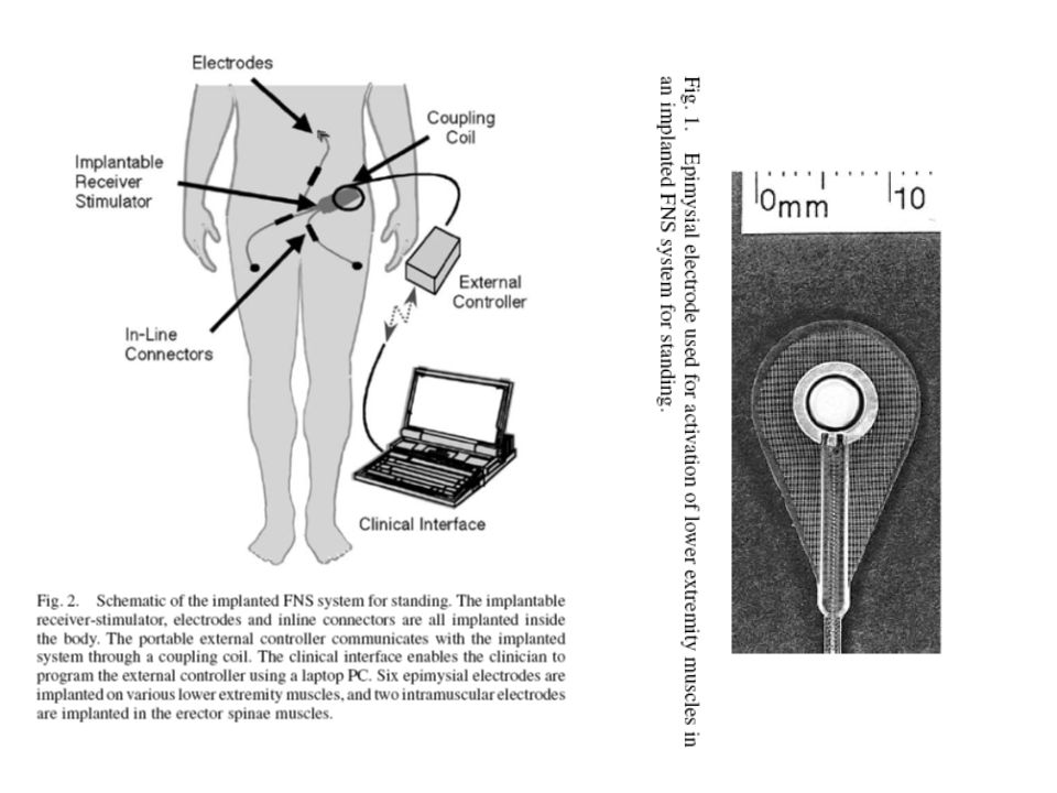
Electrode types Surface: Implantable:
Skin has high resistance, and high current needs to be passed before muscle is activated. (Large area is stimulated, unpleasant side effects). Implantable: Epimysial (next slide) Intramuscular
. Implantable: Epimysial (next slide) Intramuscular.")
42
A MULTICENTER STUDY OF AN IMPLANTED NEUROPROSTHESIS
FOR RESTORING HAND GRASP IN TETRAPLEGIA P. Hunter Peckham, PhD*†‡; Michael W. Keith, MD*†‡; Kevin L. Kilgore, PhD*†‡; Julie H. Grill, MS§; Kathy S. Wuolle, OTR/L, CHT§; Geoffrey B. Thrope§; Peter Gorman, MDxx¶;

43
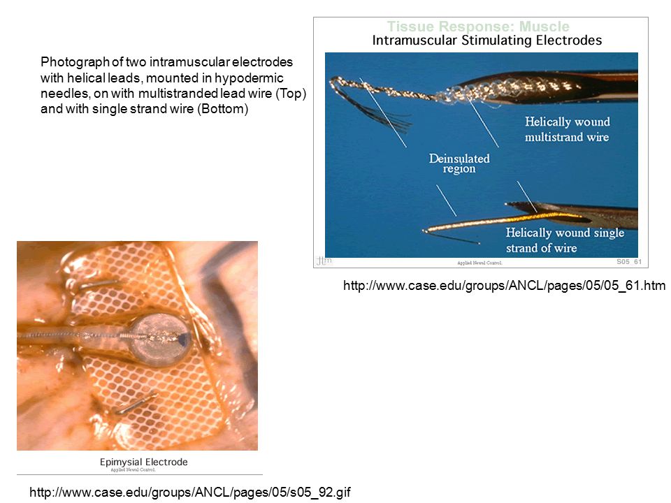
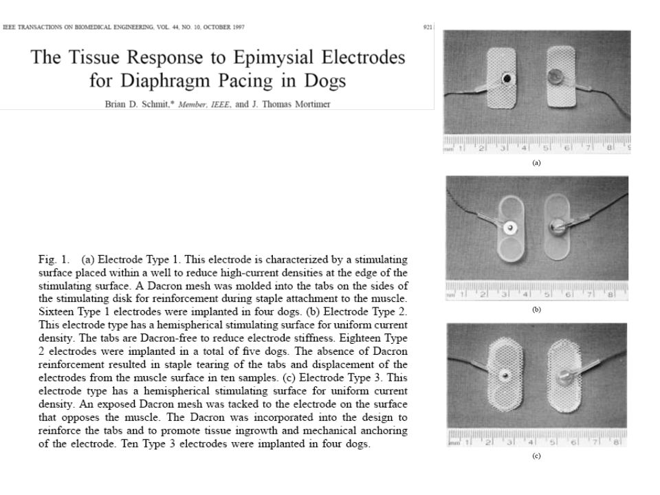
Epimysial versus intramuscular electrodes
Epimysial and intramuscular are invasive. Epimysial touches the epimysia (outer sheath of the muscle), near the entry point of the nerve, and is subcutaneously secured. Intramuscular: inserted through a needle, the needle is retracted, the barbed tips of the “wire” secure it in the muscle.
, near the entry point of the nerve, and is subcutaneously secured. Intramuscular: inserted through a needle, the needle is retracted, the barbed tips of the wire secure it in the muscle.")
44
Photograph of two intramuscular electrodes with helical leads, mounted in hypodermic needles, on with multistranded lead wire (Top) and with single strand wire (Bottom)
46
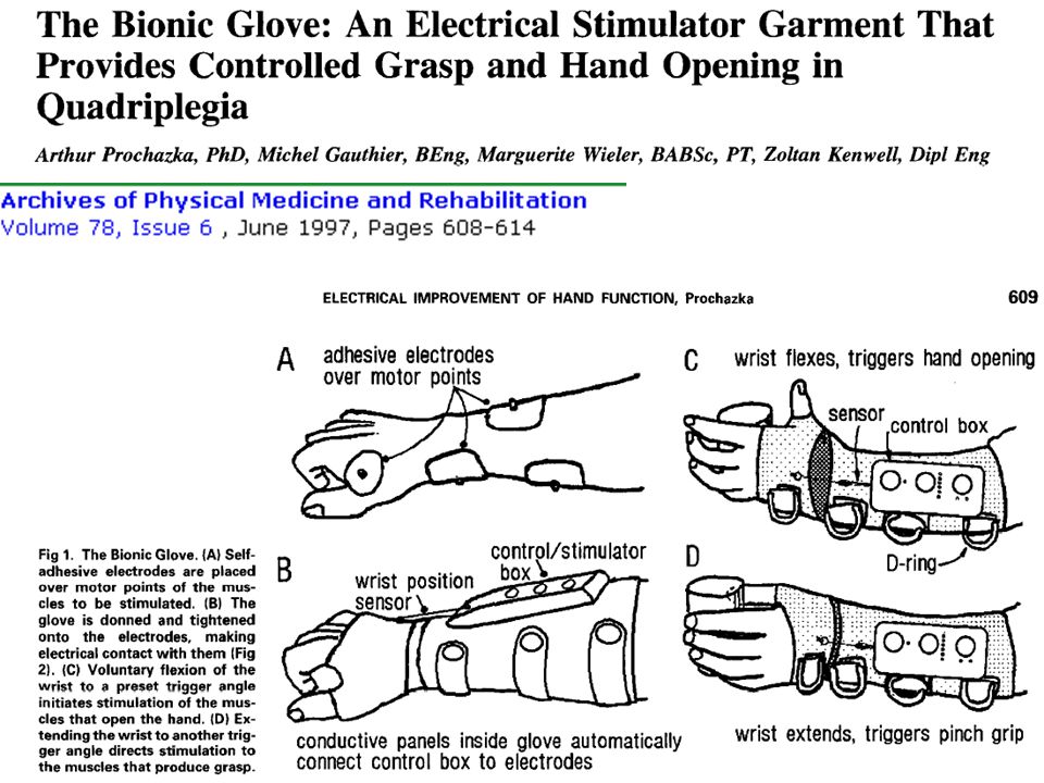
Upper extremity applications
Restoring hand grasp and release Handmaster (Ness, Israel) Bionic Glove (Prochazka) Freehand system (NeuroControl)
 Bionic Glove (Prochazka) Freehand system (NeuroControl)")
47
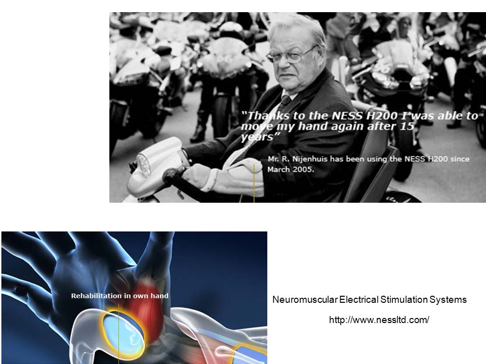
Neuromuscular Electrical Stimulation Systems
48
The NESS H200 is a non-invasive, portable device for combating and treating the consequences of brain damage. This personal system is the outcome of many years of development. It is an incorporation and integration of the most effective state of the art upper limb rehabilitation technologies in a single system. It brings the fruits of the latest clinical laboratory research and expertise into the homes of patients for independent use.

50
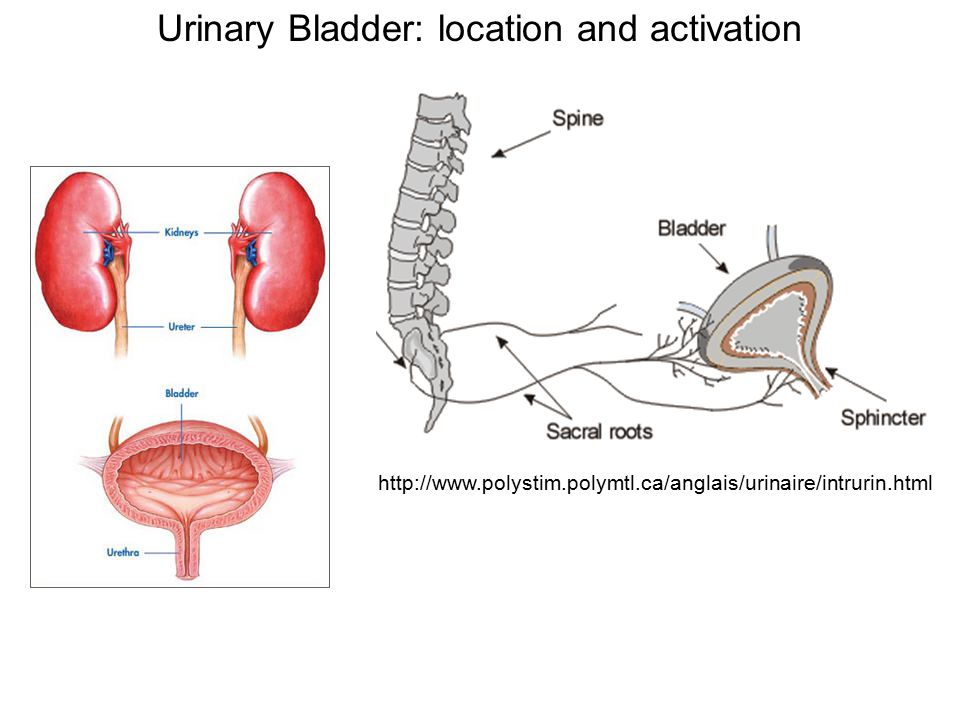
Urinary Bladder: location and activation
51
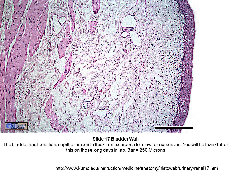
Urinary Bladder: histology
Tutorial Name: Neoplasia ConceptName: In situ carcinoma Slide Name: Bladder Transitional Epithelium Image Description: Transitional epithelium is found only in the conducting passages of the urinary system. Note the columnar surface cells with their large nuclei and prominent nucleoli. These are typical of transitional epithelium. Structures Structure Descriptions lamina propria In the bladder, this is the rather dense connective tissue layer beneath the epithelium. transitional epithelium When the bladder is not distended (as in this slide), the line of swollen cells at the surface is particularly evident.
, the line of swollen cells at the surface is particularly evident.")
52
Slide 17 Bladder Wall The bladder has transitional epithelium and a thick lamina propria to allow for expansion. You will be thankful for this on those long days in lab. Bar = 250 Microns
53
Urinary Bladder: how does it really look?
(right) (left)
 (left)")
54
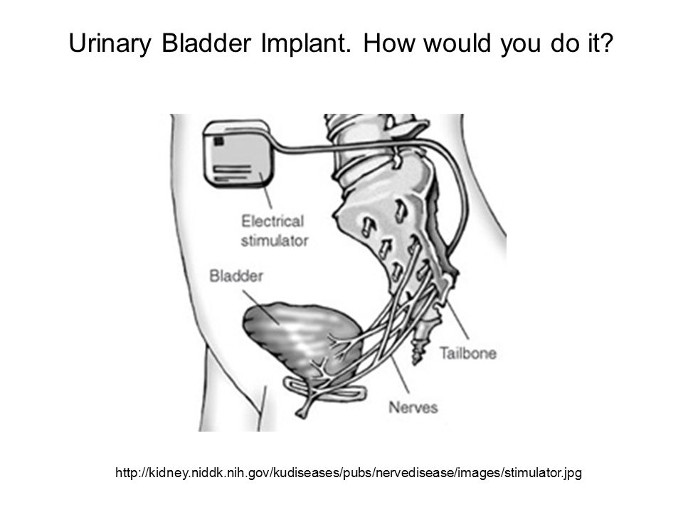
Urinary Bladder Implant. How would you do it?
55
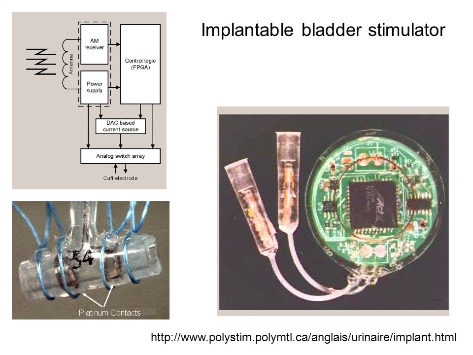
Implantable bladder stimulator
56
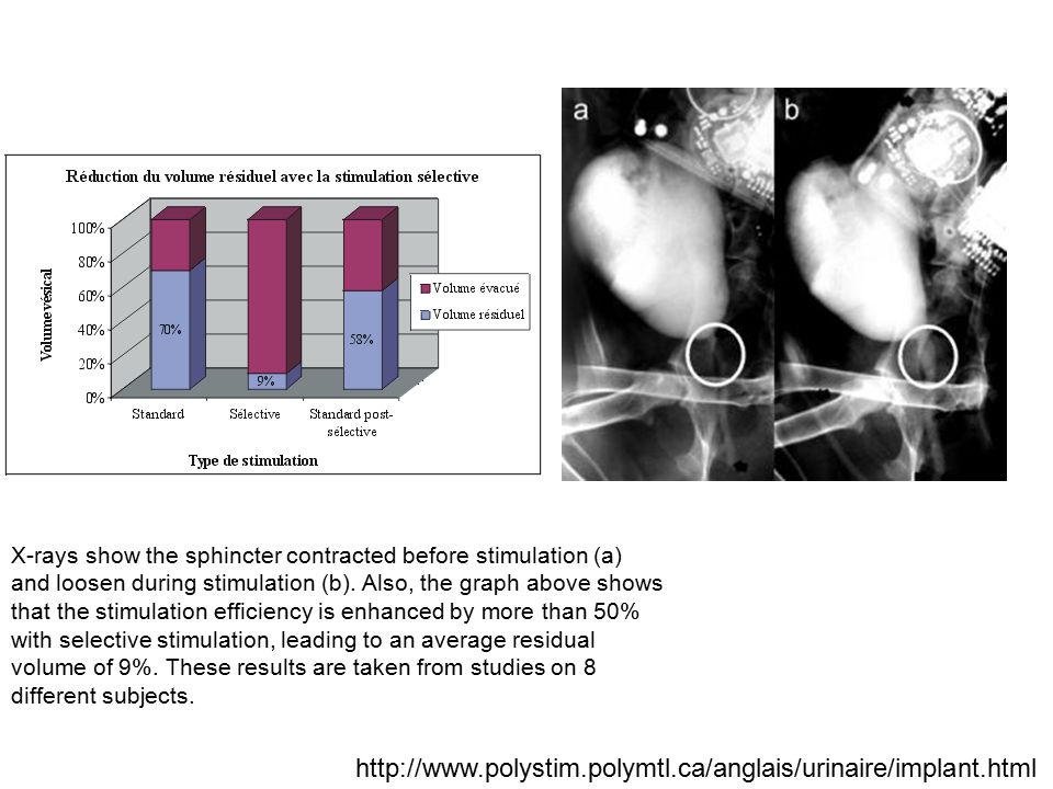
X-rays show the sphincter contracted before stimulation (a) and loosen during stimulation (b). Also, the graph above shows that the stimulation efficiency is enhanced by more than 50% with selective stimulation, leading to an average residual volume of 9%. These results are taken from studies on 8 different subjects.
57
Medtronic’s InterStimTM Bladder Stimulator
It measures 2.4 inches (6cm) by 2.2 (5.5cm) by 0.4 inches (1cm), with a weight of 1.5 ounces (42 grams)
 by 2.2 (5.5cm) by 0.4 inches (1cm), with a weight of 1.5 ounces (42 grams) pagename=Medtronic/Website/ConditionArticle&ConditionName=Urgency-Frequency&Article=urinary_art_device.")
58
Spinal Reflex – what is it?
60
Homework 7 Find, in the literature (IEEE, for example) a paper presenting a graph or numbers of FES results, with stimulus intensity versus force (by the muscle). Copy the figure or make one (out of the numbers) and explain (one paragraph is enough) what the implant is for, and what the regions you see are (plateau, high gain, linear, etc). Write me an with the time and day you can come present your project. It should be a 20min deal. I would like to see all of you on Monday, but if you can’t make it, my available days and times are: Monday, Nov 6th, either between 9am and 3pm, or from 5:15 to 7pm. Tuesday Nov 7th, afternoon (12pm to 3:30pm) Wednesday Nov 8th, from 8am to 4pm. You should bring a small presentation on your project. Maximum of 10 slides. Be ready to answer questions. This will be the second phase of you project, and you will be graded for it (not as a homework).
 a paper presenting a graph or numbers of FES results, with stimulus intensity versus force (by the muscle). Copy the figure or make one (out of the numbers) and explain (one paragraph is enough) what the implant is for, and what the regions you see are (plateau, high gain, linear, etc). Write me an with the time and day you can come present your project. It should be a 20min deal. I would like to see all of you on Monday, but if you can’t make it, my available days and times are: Monday, Nov 6th, either between 9am and 3pm, or from 5:15 to 7pm. Tuesday Nov 7th, afternoon (12pm to 3:30pm) Wednesday Nov 8th, from 8am to 4pm. You should bring a small presentation on your project. Maximum of 10 slides. Be ready to answer questions. This will be the second phase of you project, and you will be graded for it (not as a homework).")
61
Electrical Stimulation of the Neuromuscular system: mathematical derivations and simulations

62
Gradient of p (where p is a scalar field): a vector field!
The “del” operator (nabla, or ) Gradient of p (where p is a scalar field): a vector field!
 Gradient of p (where p is a scalar field): a vector field!")
63
Now we want to multiply a vector field v by the gradient.
Dot product between vectors a(x,y,z) and b(x,y,z): _________________________________________ Cross product between same vectors: ________________________________________
 and b(x,y,z): _________________________________________. Cross product between same vectors: ________________________________________.")
64
1) Dot product between gradient and v(x,y,z):
Defined as the DIVERGENCE of v (it’s a scalar!) 2) Cross product between gradient and v(x,y,z): Defined as the CURL of v (it’s a vector!)
 2) Cross product between gradient and v(x,y,z): Defined as the CURL of v (it’s a vector!)")
65
Laplacian operator (2): divergence of the gradient.
Scalar field!

66
Introduction Restoring function is not immediate in paralysis.
Ex. FreeHand (by NeuroControl™) FES (functional electrical stimulation): stimulate the neuromuscular junction, neuron is stimulated first (less charge needed) Phrenic nerve stimulation: restore respiration (ventilation)
 FES (functional electrical stimulation): stimulate the neuromuscular junction, neuron is stimulated first (less charge needed) Phrenic nerve stimulation: restore respiration (ventilation)")
67
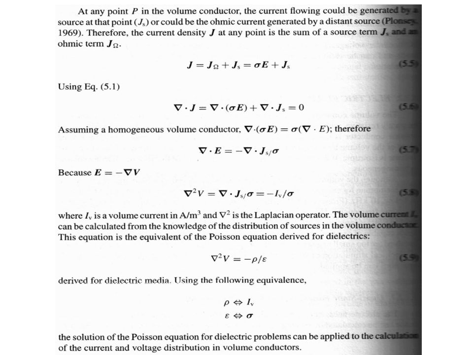
Quasi-static formulation of Maxwell’s equations
______________ Equivalence between dielectric and conductive media: It helps to look in static fields (due to point charges) and relate to fields due to current sources and sinks.
 and relate to fields due to current sources and sinks.")
69
Now let’s derive the voltage at a point along the axon of a neuron being stimulated by an electrode with a monopolar current source. (See notes)
")
70
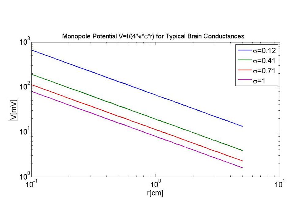
I=1mA

71
The Matlab code should be either VERY simple, or understandable (if you have never programmed in Matlab in your life). i=1e-3; % current. Assume I=1mA sigma=linspace(.12, 1, 4); % conductivity range r=linspace(.001, .05, 100); % axon distance range (in meters) for k=1:4; for j=1:100; v(k,j)=i/(4*pi*sigma(k)*r(j)); end; plot(r*100,v*1000); grid xlabel('r[cm]'); ylabel('V[mV]'); title('Plot of Monopole Potential V=I/4*\pi*\sigma*r for Typical Brain Conductances');
; % conductivity range. r=linspace(.001, .05, 100); % axon distance range (in meters) for k=1:4; for j=1:100; v(k,j)=i/(4*pi*sigma(k)*r(j)); end; plot(r*100,v*1000); grid. xlabel( r[cm] ); ylabel( V[mV] ); title( Plot of Monopole Potential V=I/4*\pi*\sigma*r for Typical Brain Conductances );")
73
Voltage along the axon due to a bipolar source
Voltage along the axon due to a bipolar source. Current through one electrode has the same amplitude (but opposite sign) as current through the other electrode.
 as current through the other electrode.")
74
I=1mA, d=0.1mm y=10mm x=r

75
Now plot both sides of an axon – orthodromic and antidromic – for the bipolar stimulation.

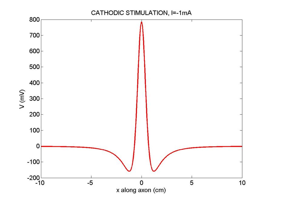
78
MONOPOLAR STIM EXTRACELLULAR V ALONG THE FIBER ANODIC STIMULATION CATHODIC STIMULATION

79
Iel=1mA, rhoe=1 kOhm.m, z=10mm

Similar presentations


 Nervous system functions Structure of a neuron Sensory, motor, inter- neurons Membrane potential Sodium.>")


 Conduct ________ _________ & __________ impulses (stimuli) __________.>")
