Download presentation
Presentation is loading. Please wait.

2
Results of Kern Method

3
Basic Kinematic Details Group No. Tube Side Velocity (m/s) Number of Tubes Shell Diameter length STHX (m) Ds/L 1 2 3 4 5
 Number of Tubes Shell Diameter length STHX (m) Ds/L")
4
Performance Details Group No. Number of Tubes Tube side Re Shell side Re Tube side h (W/m 2.K) Shell side h (W/m 2.K) 1 2 3 4 5
 Shell side h (W/m 2.K)")
5
Performance Details Group No. Tube side p, Pa Shell side p, kPa U clean U fouled 1 2 3 4 5

6
Actual Shell Side Heat Transfer Coefficient : Bell-Delaware Method P M V Subbarao Professor Mechanical Engineering Department I I T Delhi Five corrections to Cross Flow Heat Transfer…..

8
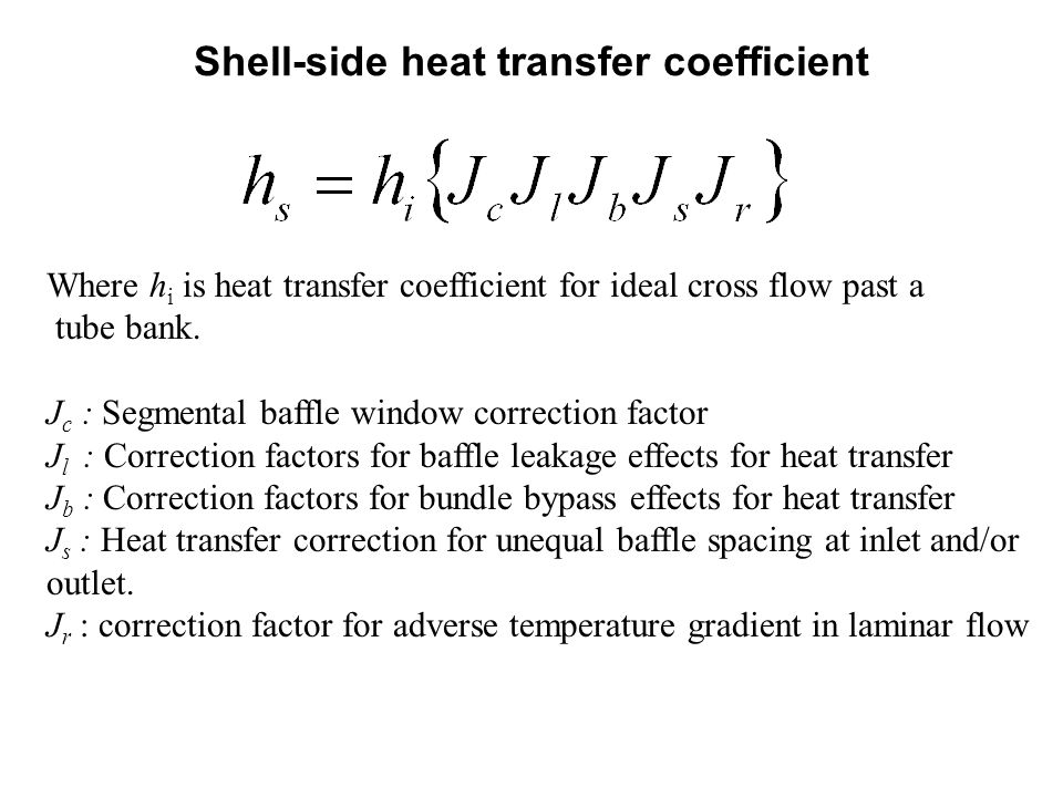
Shell-side heat transfer coefficient Where h i is heat transfer coefficient for ideal cross flow past a tube bank. J c : Segmental baffle window correction factor J l : Correction factors for baffle leakage effects for heat transfer J b : Correction factors for bundle bypass effects for heat transfer J s : Heat transfer correction for unequal baffle spacing at inlet and/or outlet. J r : correction factor for adverse temperature gradient in laminar flow

9
Heat transfer coefficient for Ideal Cross Flow

10
Area for Ideal Cross Flow

11
Selection of Shell Diameter A simple but reasonably accurate correlation was developed by Bell’s Group for single pass. CL is tube layout constant, CL =0.87 for 30º and 60º layouts or CL=1.0 for 45º and 90º layouts. For multipass arrangement, a correction factor ψ n must be used to account for the decrease of tube count due to tube pass

13
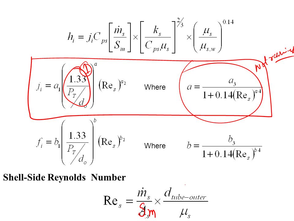
Where Shell-Side Reynolds Number

14
Coefficients of Correlations

16
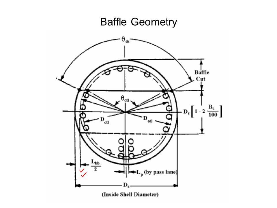
Baffle Geometry

17
Segmental baffle window correction factor, J c

18
Segmental Baffle Cut Geometry Segmental baffle cut height :L bch

19
Recommended segmental baffle cut values

20
J l : Correction factors for baffle leakage effects for heat transfer S sb is the shell-to-baffle leakage area. S tb is the tube-to-baffle hole leakage area. S m is the cross flow area at the bundle centerline

21
Shell-to-baffle leakage area The shell-to-baffle leakage area within the circle segment occupied by the baffle is calculated as: L sb is the diametral leakage clearance between the shell diameter and the baffle diameter, D b.

22
Tube-to-baffle hole leakage area for one baffle The total tube-to-baffle leakage area within one baffle is S tb.

23
Correction factors for bundle bypass effects for heat transfer J b, and pressure drop R b L ptl =0 for single pass

25
Unequal Baffle Spacing

26
Heat transfer correction for unequal baffle spacing at inlet and/or outlet, J s n is approximately a constant, found to be 0.6 for laminar flow and 0.333 for turbulent flow. If L * is larger than 2, it would be considered poor design, especially if combined with low N b. In such cases an annular distributor or other measures should be used.

27
Heat transfer correction factor for adverse temperature gradient in laminar flow where N c is the total number of tube rows crossed in the entire heat exchanger:

32
Shell side Fluid Flow in STHE

Similar presentations


>")


