Download presentation
Presentation is loading. Please wait.

1
Heart Rhythm Devices in the ER
Soori Sivakumaran BASc MEng MD PEng FRCPC Medical Director, Heart Rhythm Device Clinic, Mazankowksi Alberta Heart Institute Associate Clinical Professor of Medicine University of Alberta

2
Devices are common In Canada 2011 MAHI/U of A Hospital 2011/2012
5200 new ICDs, 2076 replacement ICDs MAHI/U of A Hospital 2011/2012 210 new ICDs, 71 ICD generator changes 261 new pacemakers, 73 pacemaker generator changes HRDC MAHI/U of A 1598 pacemaker patients, 1035 ICD patients 5647 patient clinic visits Chrysalis report 2011, MEDEC Alberta Health Services

3
ER Device Presentations
Post-operative complications Symptoms due to the device working properly Symptoms due to the device working improperly Bystander for unrelated presentations May impact care of primary presentation May suspect problem with device

4
Pacemakers: Bradycardia
Symptomatic bradycardia Sinus node disease AV disease – advanced second degree or third degree heart block Asymptomatic high grade AV block Not PACs with block, Type 1 second degree (inc. 2:1) Syncope – bifascicular block Chronotropic incompetence No reversible cause (ie. Rx, vasovagal etc) Epstein AE, DiMarco JP et al. Circulation. 2008;117:
 Syncope – bifascicular block. Chronotropic incompetence. No reversible cause (ie. Rx, vasovagal etc) Epstein AE, DiMarco JP et al. Circulation. 2008;117:")
5
The Pulse Generator: Contains a battery that provides the energy for sending electrical impulses to the heart Houses the circuitry that controls pacemaker operations Circuitry Lithium-iodine is the most commonly used power source for today’s pacemakers. Microprocessors (both ROM and RAM) control sensing, output, telemetry, and diagnostic circuits. Battery Image
 control sensing, output, telemetry, and diagnostic circuits. Battery. Image")
6
Transvenous Leads Have Different “Fixation” Mechanisms
Passive fixation The tines become lodged in the trabeculae (fibrous meshwork) of the heart Active Fixation The helix (or screw) extends into the endocardial tissue Allows for lead positioning anywhere in the heart’s chamber Images
 of the heart. Active Fixation. The helix (or screw) extends into the endocardial tissue. Allows for lead positioning anywhere in the heart’s chamber. Images")
7
Pacemaker Components Combine with Body Tissue to Form a Complete Circuit
Pulse generator: power source or battery Leads or wires Cathode (negative electrode) Anode (positive electrode) Body tissue Lead IPG In a bipolar system, body tissue is part of the circuit only in the sense that it affects impedance (at the electrode-tissue interface). In a unipolar system, contact with body tissue is essential to ground the IPG and allow pacing to occur. Anode Cathode
 Anode (positive electrode) Body tissue. Lead. IPG. In a bipolar system, body tissue is part of the circuit only in the sense that it affects impedance (at the electrode-tissue interface). In a unipolar system, contact with body tissue is essential to ground the IPG and allow pacing to occur. Anode. Cathode.")
8
NBG Code P: Simple programmable V: Ventricle V: Ventricle T: Triggered
Chamber Paced II Sensed III Response to Sensing IV Programmable Functions/Rate Modulation V Antitachy Function(s) P: Simple programmable V: Ventricle V: Ventricle T: Triggered P: Pace M: Multi- programmable A: Atrium A: Atrium I: Inhibited S: Shock D: Dual (A+V) D: Dual (A+V) D: Dual (T+I) C: Communicating D: Dual (P+S) The first letter refers to the chamber(s) being paced The second letter refers to the chamber(s) being sensed The third letter refers to the pacemaker’s response to a sensed event: T = Triggered D = Dual (inhibited and triggered*) I = Inhibited O = No response *In a single chamber mode, “triggered” means that when an intrinsic event is sensed, a pace is triggered immediately thereafter. In a dual chamber mode, “triggered” means that a sensed atrial event will initiate (trigger) an A-V delay. The fourth letter denotes the pacemaker’s programmability and whether it is capable of rate response: P = Simple Programmable (rate and/or output) M = Multiprogrammable (rate, output, sensitivity, etc.) C = Communicating (pacemaker can send/receive information to/from the programmer) R = Rate Modulation O = None Note that this sequence is hierarchical. In other words, it is assumed that if a pacemaker has rate modulation capabilities, “R”, that it also can communicate, “C”. The fifth letter represents the pacemaker’s antitachycardia functions: P = Pace D = Dual (pace and shock available) S = Shock O = None You may want to test the audience by having them describe different pacing modes. More modes and ECG strips are found in Module 2. O: None O: None O: None R: Rate modulating O: None S: Single (A or V) S: Single (A or V) O: None
 P: Simple. programmable. V: Ventricle. V: Ventricle. T: Triggered. P: Pace. M: Multi- programmable. A: Atrium. A: Atrium. I: Inhibited. S: Shock. D: Dual (A+V) D: Dual (A+V) D: Dual (T+I) C: Communicating. D: Dual (P+S) The first letter refers to the chamber(s) being paced. The second letter refers to the chamber(s) being sensed. The third letter refers to the pacemaker’s response to a sensed event: T = Triggered D = Dual (inhibited and triggered*) I = Inhibited O = No response. *In a single chamber mode, triggered means that when an intrinsic event is sensed, a pace is triggered immediately thereafter. In a dual chamber mode, triggered means that a sensed atrial event will initiate (trigger) an A-V delay. The fourth letter denotes the pacemaker’s programmability and whether it is capable of rate response: P = Simple Programmable (rate and/or output) M = Multiprogrammable (rate, output, sensitivity, etc.) C = Communicating (pacemaker can send/receive information to/from the programmer) R = Rate Modulation. O = None. Note that this sequence is hierarchical. In other words, it is assumed that if a pacemaker has rate modulation capabilities, R , that it also can communicate, C . The fifth letter represents the pacemaker’s antitachycardia functions: P = Pace D = Dual (pace and shock available) S = Shock O = None. You may want to test the audience by having them describe different pacing modes. More modes and ECG strips are found in Module 2. O: None. O: None. O: None. R: Rate modulating. O: None. S: Single. (A or V) S: Single. (A or V) O: None.")
9
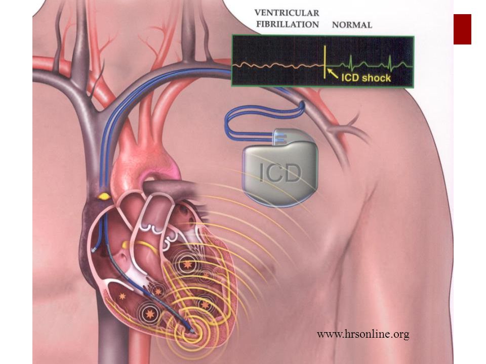
Automatic Implantable Cardioverter Defibrillators
24/7 cardiac monitoring and intervention Treat VT/VF Anti-tachycardia pacing (ATP) for VT Cardioversion/Defibrillation for VT/VF Treat bradyarrhythmias Full pacing functions (single, dual) Treat heart failure Biventricular pacing
 for VT. Cardioversion/Defibrillation for VT/VF. Treat bradyarrhythmias. Full pacing functions (single, dual) Treat heart failure. Biventricular pacing.")
11
Secondary Prevention Survivors of VT/VF arrest w/o reversible cause
ICDs associated with a mortality reduction of 27%1 Patients with inducible VT on EPS Syncope and ischemic heart disease Non sustained VT and ischemic heart disease Syncope and dilated cardiomyopathy Unfortunately most patients don’t survive first episode 1AVID Investigators. N Engl J Med. 1997;337:

12
Consider Primary Prophylaxis AICD
EF less than or equal 35% Ischemic cardiomyopathy (CCS Class 1) more than 4 weeks post most recent MI more than 3 months post revascularization Dilated cardiomyopathy with Class II, III heart failure (CCS Class II a) more than nine months after diagnosis Benefit modest with ARR approximately 2%/year Other high risk conditions eg. Long QT, ARVC etc.
 more than 4 weeks post most recent MI. more than 3 months post revascularization. Dilated cardiomyopathy with Class II, III heart failure (CCS Class II a) more than nine months after diagnosis. Benefit modest with ARR approximately 2%/year. Other high risk conditions eg. Long QT, ARVC etc.")
14
Discrimination: SVT vs VT
Heart Rate A-V relationship Onset Stability Morphology

15
Morphology Analysis

16
Re-Entry Murgatroyd, Krahn et al. Handbook of Cardiac Electrophysiology

17
Anti-Tachycardia Pacing
Pain free way of terminating VT Burst pacing faster than the VT rate More effective on slower VTs Can accelerate VT Murgatroyd, Krahn et al. Handbook of Cardiac Electrophysiology

18
Cardiac Resychronization Therapy
right atrium coronary sinus right ventricle Hare, NEJM 2002;346:1902-5

21
Magnets and Devices Pacemakers
Device paces at its predefined magnet rate Asynchronous mode (DOO, VOO) ICDs Disables tachycardia detection Does NOT affect pacing therapies
 ICDs. Disables tachycardia detection. Does NOT affect pacing therapies.")
22
Pacemaker Presentations
Failing to capture Pacing spikes – no capture Failing to sense Pacing occurs where it shouldn’t – like on T wave Failing to output Oversensing – no pacing spikes because the device sees a signals it thinks are coming from heart beats – but they are not!

23
Pacing - Tachyardia Failure to mode switch – tracking of atrial fibrillation/flutter with rapid paced ventricular rate Medications won’t control the rate Pacemaker Mediated Tachycardia Retrograde conduction to the atrium from a PVC starts a rapid pacing cycle via the pacemaker
![]()
24
Hysteresis

25
The DAVID Study – Adverse Effects of RV Pacing
Objective To compare the efficacy of dual chamber pacing with back-up VVI pacing in patients with a standard ICD indication 506 patients randomized to DDDR pacing at 70 bpm vs VVI back-up pacing at 40 bpm No indication for bradycardia pacing Maximal tolerated medical therapy Clinical motivations by the device industry to develop unique algorithms (Search AV, AV Hysteresis, etc.) and/or pacing modes (AAISafeR etc.) to actively manage ventricular pacing were brought about by the well-understood relationship between the electrical-mechanical synchrony required by the heart to maintain optimal hemodynamic performance. Specifically, the atrial chamber contractions provide an important filling contribution to ventricular output. Coordinated pumping between the left and right ventricles is necessary to achieve adequate ejection fractions. When this AV synchrony and ventricular synchronization is lost, patients may suffer from poor systolic function and low cardiac output. JAMA. 2002;288(24):
 and/or pacing modes (AAISafeR etc.) to actively manage ventricular pacing were brought about by the well-understood relationship between the electrical-mechanical synchrony required by the heart to maintain optimal hemodynamic performance. Specifically, the atrial chamber contractions provide an important filling contribution to ventricular output. Coordinated pumping between the left and right ventricles is necessary to achieve adequate ejection fractions. When this AV synchrony and ventricular synchronization is lost, patients may suffer from poor systolic function and low cardiac output. JAMA. 2002;288(24):")
26
Outcome: DAVID Trial The DAVID Trial Investigators, JAMA 2002;288:

27
MVP Basic Operation DDD(R) Switch Figure: If your patient develops persistent loss of conduction, the device will automatically switch to DDD(R) operation, but continue to periodically look for restored conduction. Details on this switch provided in subsequent slides. DDD(R) Switch Ventricular support if loss of A-V conduction is persistent Image
 Switch Figure: If your patient develops persistent loss of conduction, the device will automatically switch to DDD(R) operation, but continue to periodically look for restored conduction. Details on this switch provided in subsequent slides. DDD(R) Switch Ventricular support if loss of A-V conduction is persistent. Image")
28
Complex Pacing Algorithms
Minimize RV Pacing Mode switching algorithms AV delay extension algorithms Prevention of atrial fibrillation Atrial overdrive / PAC suppression Rate smoothing in persistent atrial fibrillation Pacing in ventricle may result in a slower average ventricular rate

29
Patient Shocks Normal function of the AICD
Patient feels well post shock(s) Leave message with AICD Clinic Scheduled assessment within few days Patient feels unwell post shock(s) Go to nearest ER Patient with an device/lead under a manufacturer’s advisory may require urgent assessment also
 Leave message with AICD Clinic. Scheduled assessment within few days. Patient feels unwell post shock(s) Go to nearest ER. Patient with an device/lead under a manufacturer’s advisory may require urgent assessment also.")
30
Inappropriate Shocks Shocks received for reasons other than VT/VF
Causes include: Sinus tachycardia Atrial fibrillation with a rapid ventricular response Other supraventricular tachyarrhythmias Lead Fracture External noise

31
Complications Lead dislodgement 2.3% Early ICD system infection 1.9%
Pneumothorax 0.6% Device malfunction 0.5% Serious bleeding 0.4% Venous thrombosis 0.2% Cardiac perforation 0.1% CCS/CHRS Position Paper on Implantable Cardioverter Defibrillator (ICD) Use in Canada
 Use in Canada.")
32
Post-op Site Check

33
Hematoma

34
Post AICD Implant – 12 months

35
` Parsonnet V, Trivedi A. Circulation ;102:1192.

36
Lead Infection Clinical symptoms suggestive of systemic infection and positive blood cultures warrant further evaluation with TEE “Strands” and clot on leads can be a normal finding Sometimes appearance can be highly suggestive of infection

37
Leads Attached to Veins by Fibrotic Tissue

38
Preventing Infections
ECG Electrode on device site can cause erosion Starting heparin or low molecular weight heparin will cause a large hematoma Central lines provide a route for sepsis and lead infection Sepsis from any source can settle on the device leads

39
Peri-Operative Device Management
Device type and indication Pacemaker dependence Surgery location Accessibility to device site during procedure Canadian Cardiovascular Society/Canadian Anesthesiologists/Canadian Heart Rhythm Society Joint Position Statement on the Perioperative Management of Patients with Implanted Pacemakers, Defibrillators and Neurostimulating Devices. CJC 28(2012)
")
40
Reason for a device check
Patient symptoms Shocks Syncope/Significant presyncope Palpitations Also consider: SOBOE: chronotropic incompetence, loss of BiV pacing Documented device failure (on ECG) Patient lost to device follow-up
 Patient lost to device follow-up.")
41
Remember Settings/notes available from Device Clinic
Presence of patient in hospital is not an indication to check the device We’re here to help

42
Conclusion ≠

43
Heart Rhythm Device Clinic
Pacemaker Clinic – Nurse run, physician supervised 4 weeks, 3 months, 6 months, 12 months Assess patient symptoms Lead performance Battery Status Programming changes ICD Clinics – EP Physician attended Anti-arrhythmic medications checked Episodes recorded by the device reviewed

44
CRT requires wide complex ECG and Class II+ CHF

Similar presentations


>")


>")
 Janet McComb Freeman Hospital Newcastle upon Tyne.>")


