Download presentation
Presentation is loading. Please wait.

1
Chapter Four Separation

2
Separation Introduction
Natural gases produced from gas wells are normally complex mixtures of hundreds of different compounds. A typical gas well stream is a high velocity, turbulent, constantly expanding mixture of gases and hydrocarbon liquids, intimately mixed with water vapor, free water, and sometimes solids. The well stream should be processed as soon as possible after bringing it to the surface. Field processing consists of four basic processes: (1) separating the gas from free liquids such as crude oil, hydrocarbon condensate, water, and entrained solids; (2) processing the gas to remove condensable and recoverable hydrocarbon vapors; (3) processing the gas to remove condensable water vapor; and (4) processing the gas to remove other undesirable compounds, such as hydrogen sulfide or carbon dioxide. This chapter focuses on the principles of separation and selection of required separators.
 separating the gas from free liquids such as crude oil, hydrocarbon condensate, water, and entrained solids; (2) processing the gas to remove condensable and recoverable hydrocarbon vapors; (3) processing the gas to remove condensable water vapor; and (4) processing the gas to remove other undesirable compounds, such as hydrogen sulfide or carbon dioxide. This chapter focuses on the principles of separation and selection of required separators.")
3
Separation of Gas and Liquids
Separation of well stream gas from free liquids is the first and most critical stage of field processing operations. Factors affecting separators type and size are: 1-Composition of the fluid mixture 2-pressure : pressure is another key factor affecting selection of separators. 3-location :Separators are also used in other locations such as upstream and downstream of compressors, dehydration units, and gas sweetening units. At these locations, separators are referred to as scrubbers, knockouts, and free liquid knockouts.

4
Basic Functions of Separators
Separators should be designed to perform the following basic functions: cause a primary-phase separation of the mostly liquid hydrocarbons from the gas stream refine the primary separation by further removing most of the entrained liquid mist from the gas refine the separation by further removing the entrained gas from the liquid stream discharge the separated gas and liquid from the vessel and ensure that no reentrainment of one into the other occurs

5
Principles of Separation
Most separators work based on the principles of gravity segregation and/or centrifugal segregation. A separator is normally constructed in such a way that it has the following features: it has a centrifugal inlet device where the primary separation of the liquid and gas is made it provides a large settling section of sufficient height or length to allow liquid droplets to settle out of the gas stream with adequate surge room for slugs of liquid it is equipped with a mist extractor or eliminator near the gas outlet to coalesce small particles of liquid that do not settle out by gravity it allows adequate controls consisting of level control, liquid dump valve, gas backpressure valve, safety relief valve, pressure gauge, gauge glass, instrument gas regulator, and piping

6
Types of Separators Three types of separators are generally available from manufacturers: vertical separators, horizontal separators: 1- single tube 2- double tube , and spherical separators. Each type of separator has specific advantages and limitations. Selection of separator type is based on several factors including characteristics of production steam to be treated, floor space availability at the facility site, transportation, and cost.

7
1-Vertical Separators Vertical separators are often used to :
1- treat low to intermediate gas/oil ratio well streams 2-treat streams with relatively large slugs of liquid. 3-They handle greater slugs of liquid without carryover to the gas outlet, and the action of the liquid level control is not as critical as in Figure 7-1. 4- Vertical separators occupy less floor space, which is important for facility sites such as those on offshore platforms where space is limited. 5-Owing to the large vertical distance between the liquid level and the gas outlet, the chance for liquid to revaporize into the gas phase is limited. due to the natural upward flow of gas in a vertical separator against the falling droplets of liquid, adequate separator diameter is required.

8
Vertical separator schematic

9
2-Horizontal Separators
Horizontal double-tube separators (Figure 7-2) are usually the first choice because of their low costs. 1-Horizontal separators are widely used for high gas/oil ratio well streams, foaming well streams, or liquid-from-liquid separation. 2-They have much greater gas/liquid interface due to a large, long, baffled gas-separation section. 3-Horizontal separators are easier to skid-mount and service, 4-require less piping for field connections. 5-Individual separators can be stacked easily into stage-separation assemblies to minimize space requirements. In horizontal separators, gas flows horizontally and, at the same time, liquid droplets fall toward the liquid surface.
 are usually the first choice because of their low costs. 1-Horizontal separators are widely used for high gas/oil ratio well streams, foaming well streams, or liquid-from-liquid separation. 2-They have much greater gas/liquid interface due to a large, long, baffled gas-separation section. 3-Horizontal separators are easier to skid-mount and service, 4-require less piping for field connections. 5-Individual separators can be stacked easily into stage-separation assemblies to minimize space requirements. In horizontal separators, gas flows horizontally and, at the same time, liquid droplets fall toward the liquid surface.")
10
2-Horizontal Separators

11
Horizontal separator schematic
Horizontal double-tube separators have all the advantages of normal horizontal single-tube separators plus much higher liquid capacities.

12
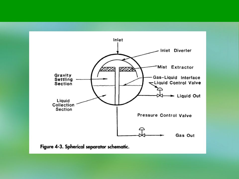
3 -Spherical Separators
Spherical separators offer an inexpensive and compact means of the separation arrangement shown in Figure 7-4.

14
Factors Affecting Separation
these types of vessels have a very limited surge space and liquid settling section. The placement and action of the liquid level control in this type of vessel is very critical. Separator operating pressure, separator operating temperature, and fluid stream composition affect the operation and separation between the liquid and gas phases in a separator. Changes in any one of these factors on a given fluid well stream will change the amount of gas and liquid leaving the separator. Generally, an increase in operating pressure or a decrease in operating temperature will increase the liquid covered in a separator. However, there are optimum points in both cases beyond which further changes will not aid in liquid recovery. Factors Affecting Separation

15
In the case of wellhead separation equipment, an operator generally wants to determine the optimum conditions for a separator to effect the maximum income. Again, generally speaking, the liquid recovered is worth more than the gas. So, high liquid recovery is a desirable feature, providing it can be held in the available storage system. Also, pipeline requirements for the Btu content of the gas may be another factor in separator operation. Without the addition of expensive mechanical refrigeration equipment, it is often unfeasible to try to lower the operating temperature of a separator.

16
The operator can also control operating pressure to some extent by use of back-pressure valves within the limitation of the flowing characteristics of the well against a set pressure head and the transmission line pressure requirements. As previously mentioned, higher operating pressure will generally result in higher liquid recovery. An analysis can be made using the well stream composition to find the optimum temperature and pressure at which a separator should operate to give maximum liquid or gas phase recovery. These calculations, known as flash vaporization calculations, require a trial-and-error solution and are more generally adapted to solution by a programmed computer.

17
Separator Design Gas Capacity
The following discussion on oil gas separator design has been adapted from Sivalls' excellent treatment of the subject. Sivalls* tables, graphs, and procedures are accepted as the standard of the industry. Gas Capacity The gas capacity of oil-gas separators has been calculated for many years from the following empirical relationship proposed by Souders-Brown:

18
where v = superficial gas velocity based on total cross-sectional area of vessel, fps A = cross-sectional area of separator, sq ft q = gas flow rate at operating conditions, cfs pL = density of liquid at operating conditions, lbm/cu ft pg = density of gas at operating conditions, lbm/cu ft K = empirical factor

19
Vertical separators K = 0.06 to 0.35, avg 0.21
Horizontal separators K = 0.40 to 0.50, avg 0.45 Wire mesh mist eliminators K = 0.35 Bubble cap trayed columns K = 0.16 for 24-in. spacing Valve tray columns K = 0.18 for 24-in. spacing

20
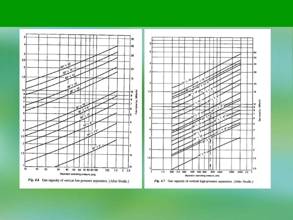
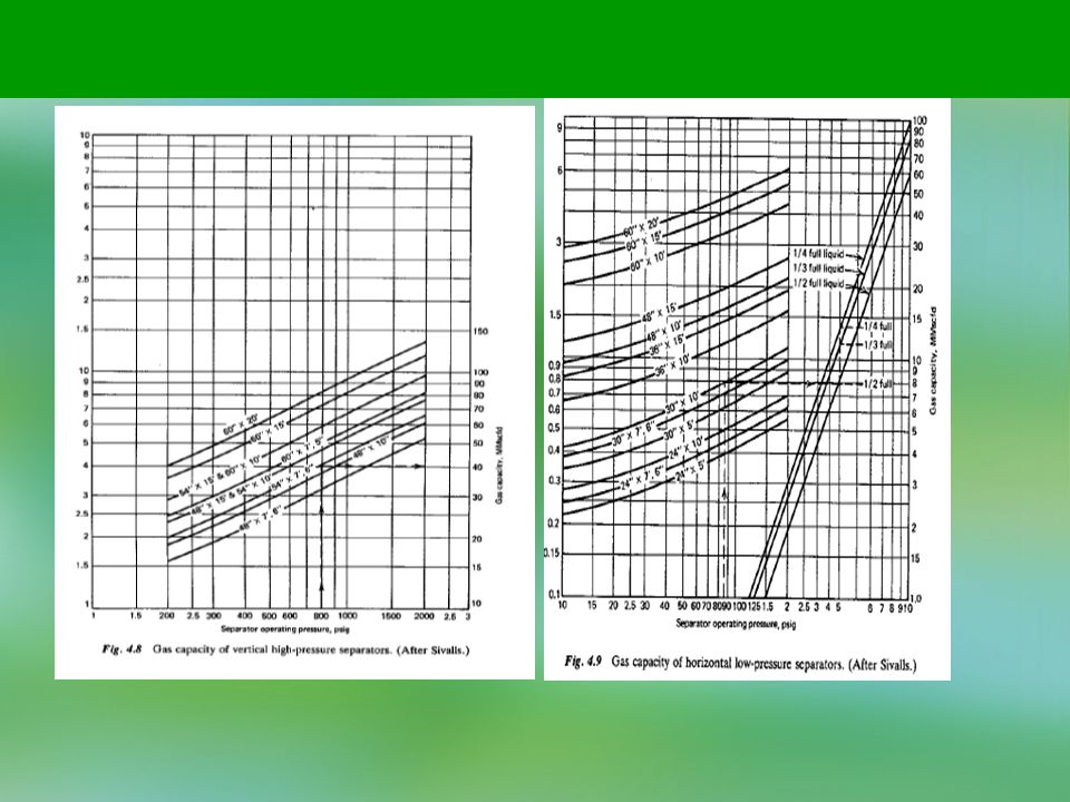
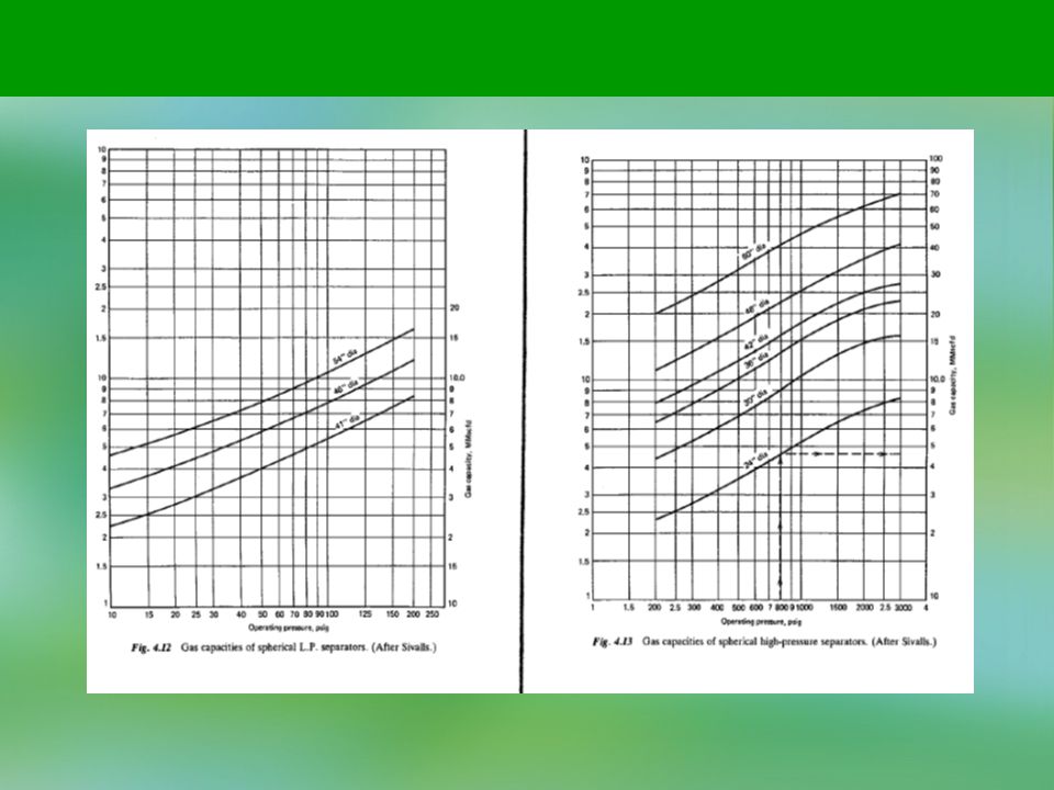
where q = gas capacity at standard conditions, MMscfd D = internal diameter, ft p = operating pressure, psia T = operating temperature, °F z = gas deviation factor Figures 4.6 to 4.13 are gas capacity charts for various standard size separators based on operating pressure.

25
Liquid Capacity The liquid capacity of a separator is primarily dependent on the retention time of the liquid within the vessel. Good separation requires sufficient time to obtain an equilibrium condition between the liquid and gas phase at the temperature and pressure of separation. The liquid capacity of a separator or the settling volume required based on retention can be determined from the following equation:

26
where W = liquid capacity, bbl/day V = liquid settling volume, bbl t = retention time, min Basic design criteria for liquid retention times in separators have been determined by numerous field tests: Oil-gas separation min High-pressure oil-gas-water separation 2 to 5 min Low-pressure oil-gas-water separation to 10 min at 100°F and up 10 to 15 min at 90°F 15 to 20 min at 80°F 20 to 25 min at 70°F 25 to 30 min at 60°F

27
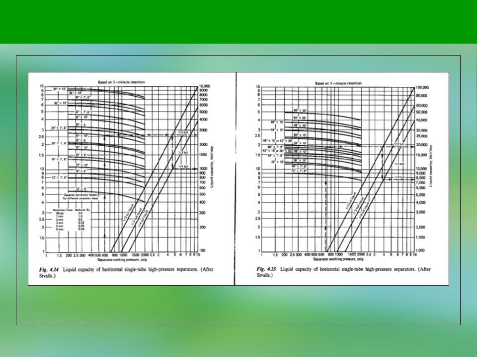
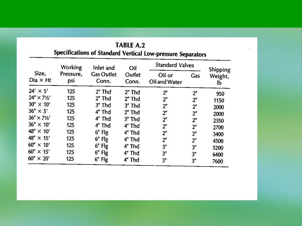
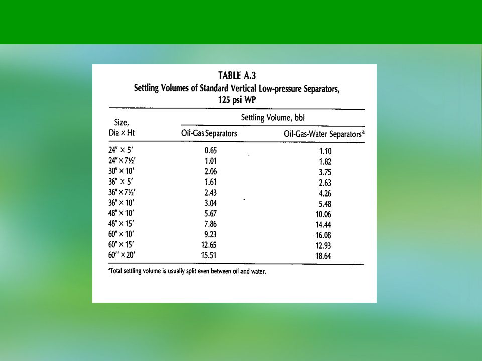
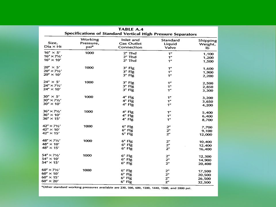
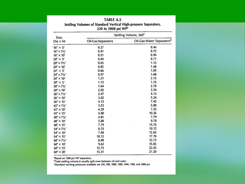
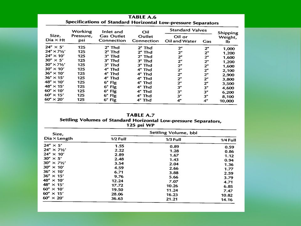
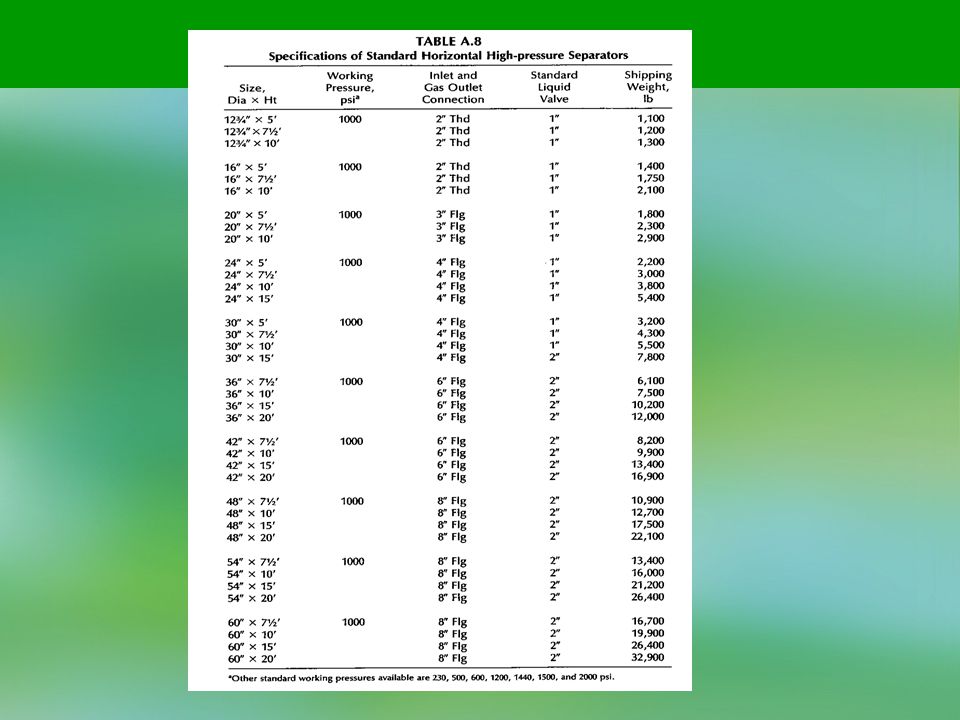
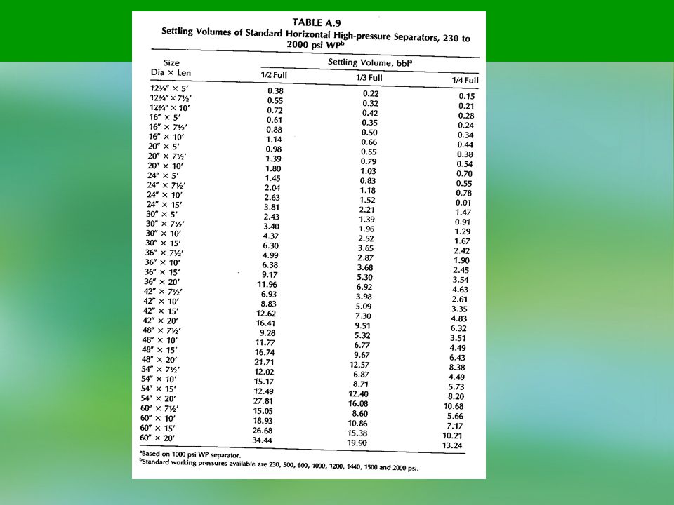
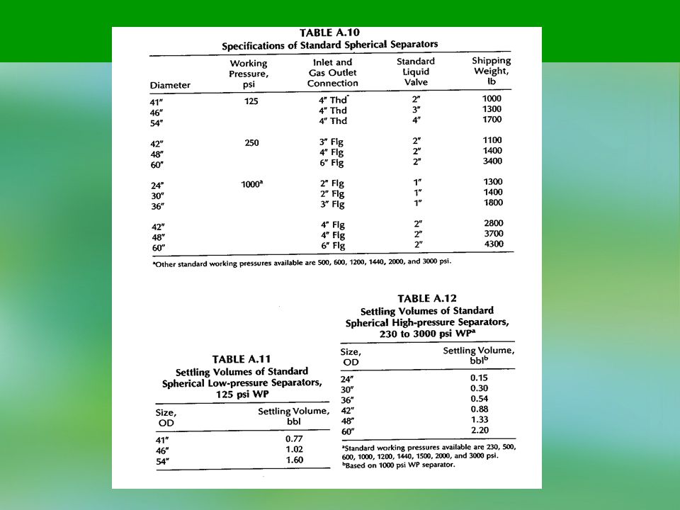
Figures 4.14 and 4.15 are sizing charts for the liquid capacity of horizontal single-tube high-pressure separators. These are based on the parameters of separator working pressure, size, and the depth of liquid used in the liquid settling section. Tables A.2 to A.12 list the standard specifications of typical oil-gas separators and the liquid-settling volumes with the conventional placement of liquid level controls. The settling volumes may determine the liquid capacity of a particular vessel. For proper sizing of both, the liquid capacity and gas capacity required should be determined.

37
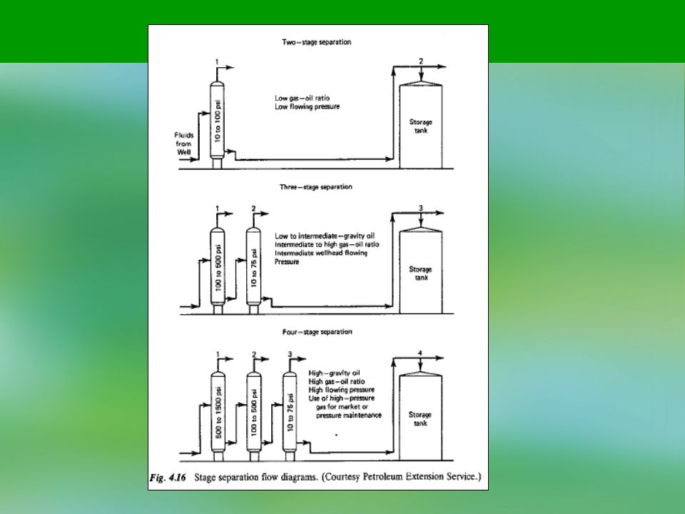
Stage Separation Stage separation is a process in which gaseous and liquid hydrocarbons are separated into vapor and liquid phases by two or more equilibrium flashes at consecutively lower pressures. As illustrated in Fig. 4.16, two-stage separation requires two separators and a storage tank; and so on. The tank is always counted as the final stage of vapor-liquid separation because the final equilibrium flash occurs in the tank. The purpose of stage separation is to reduce the pressure on the reservoir liquids a little at a time, in steps or stages, so that a more stable stock-tank liquid will result. The ideal method of separation, to attain maximum liquid recovery, would be that of differential liberation of gas by means of a steady decrease in pressure from that existing in the reservoir to the stock-tank pressure. However, to carry out this differentia! process would require an infinite number of separation stages.

39
Although three to four stages of separation theoretically would increase the liquid recovery over two stages, the net increase over two-stage separation will rarely pay out the cost of the second or third separator. Therefore, it has been generally accepted that two stages of separation plus the stock tank are considered optimum. The optimum high stage or First separator operating pressure is generally governed by the gas transmission line pressure and operating characteristics of the well. For each high or first-stage pressure, there is an optimum low-stage separation pressure that will afford the maximum liquid recovery. This operating pressure can be determined from an equation based on equal pressure ratios between the stages (Campbell):
:")
40
where: R = pressure ratio n = number of stages - 1 Pi = first-stage or high-pressure separator pressure, psia p2 = second-stage or low-pressure separator pressure, psia ps = stock tank pressure, psia

41
The magnitude of stock tank liquid recoveries are not considered in the equation.
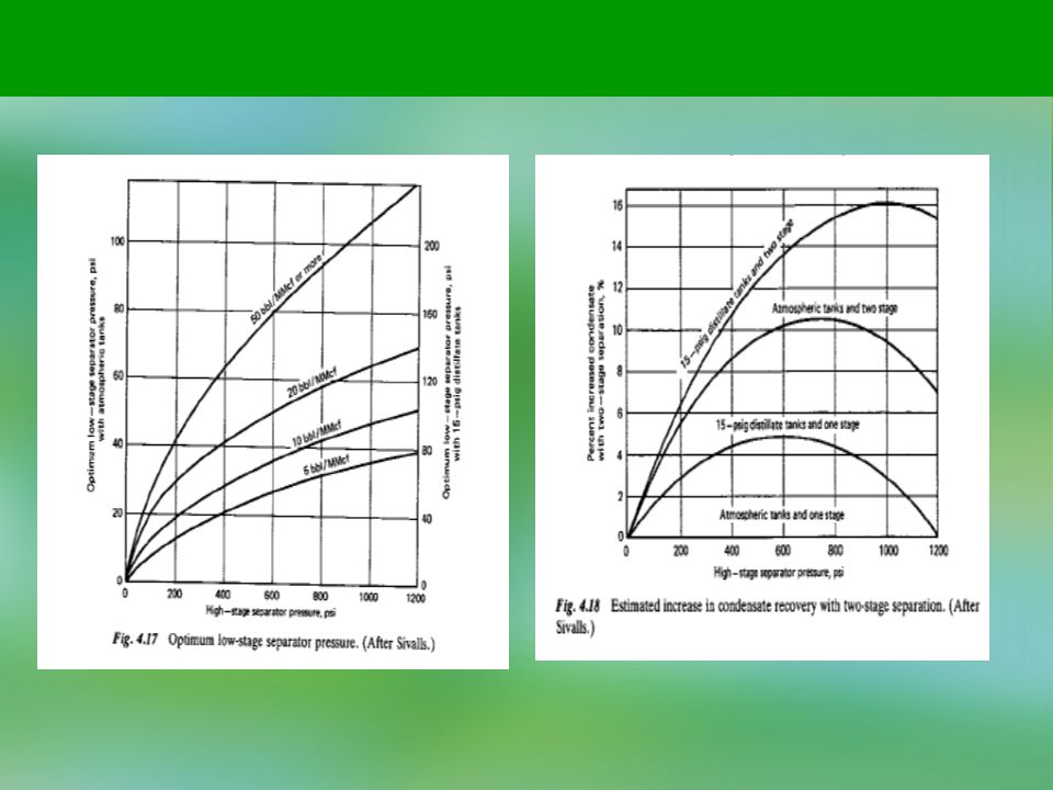
Figure 4.17 has been prepared to determine the optimum low-stage separator pressure based on the high-stage separator pressure with additional parameters of overall stock tank liquid recovery. This information has been determined from extensive field test data. Figure 4.18 is a chart illustrating the average percent increase in liquid recovery for two-stage separation over single-stage separation. By using this, an

43
Example 4.1. Size a standard oil-gas separator both vertically and horizontally for the following conditions: Gas flow rate 5.0 MMscfd Operating pressure 800 psig Condensate flow rate 20 bbl/MMscf Solution Total liquid capacity = 20 (5.0) = 100 bbl/day
 = 100 bbl/day.")
44
From Fig. 4. 7, at 800-psig operating pressure, a 20 in. x 7 ft, 6 in
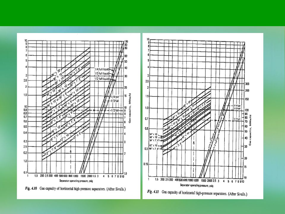
From Fig. 4.7, at 800-psig operating pressure, a 20 in. x 7 ft, 6 in. vertical separator will handle 5.4 MMscfd. From Table A.5,a20in. x 7 ft, 6 in. separator will handle the following liquid capacity: 1440V (0.65) W = = = 936 bbl/day t 1.0 From Fig. 4.10, at 800-psig operating pressure and one-half full of liquid, a 16 in. x 5 ft horizontal separator will handle 5.1 MMscfd. From Table A.9, a 16 in. x 5 ft separator will handle 1440V (0.61) W = = - = 878 bbl/day / 1.0 Therefore, a smaller horizontal separator would be required and would be more economical. For the operating pressure involved, at least a 1000-psig working pressure separator should be used.
 W = = = 936 bbl/day. t 1.0. From Fig. 4.10, at 800-psig operating pressure and one-half full of liquid, a 16 in. x 5 ft horizontal separator will handle 5.1 MMscfd. From Table A.9, a 16 in. x 5 ft separator will handle. 1440V 1440(0.61) W = = - = 878 bbl/day. / 1.0. Therefore, a smaller horizontal separator would be required and would be more economical. For the operating pressure involved, at least a 1000-psig working pressure separator should be used.")
45
Example 4.2. Size a standard vertical oil-gas separator for the following conditions:
Oil flow rate25O0 bbl/dayGas-oil ratio1000Operating pressure50 psigSolution Gas flow rate = 1000 (2500) = 2,500,000 cfd = 2.5 MMscfd From Fig. 4.6, at 50-psig operating pressure, a 36 in. x 5 ft vertical separator will handle 2.9 MMscfd. From Table A.3, a 36 in. x 5 ft separator will handle 1440V (1.61) W = = - = 2,318 bbl/day / 1.0 J Therefore, a larger separator will be required to handle the liquid load. A 30 in. x 10 ft separator will handle 1440(2.06) W = ~—- = 2,966 bbl/day
 = 2,500,000 cfd. = 2.5 MMscfd. From Fig. 4.6, at 50-psig operating pressure, a 36 in. x 5 ft vertical separator will handle 2.9 MMscfd. From Table A.3, a 36 in. x 5 ft separator will handle. 1440V 1440(1.61) W = = - = 2,318 bbl/day. / 1.0 J. Therefore, a larger separator will be required to handle the liquid load. A 30 in. x 10 ft separator will handle. 1440(2.06) W = ~—- = 2,966 bbl/day.")
46
The gas capacity of a 30 in. x 10 ft separator is 3. 75 MMscfd
The gas capacity of a 30 in. x 10 ft separator is 3.75 MMscfd. In fact, the diameter of a separator generally controls the price and a 30 in. x 10 ft separator will probably be cheaper than one that is 36 in. x 5 ft. Example A20in. x 10ft, 100-psi working pressure (WP) horizontal separa-tor is operated at one-half full liquid capacity. Can it be used on a well with the following conditions: Gas flow rate 9.0 MMscfd Line pressure 500 psig Solution From Fig. 4.10, a 20 in. x 10 ft separator will handle only 8.1 MMscfd at 500 psig. But, if a gas back-pressure valve were put on the separator and held at 800 psig, the separator would handle 10.2 MMscfd. This is accepted procedure, providing the well will flow the desired rate at 800 psig.
 horizontal separa-tor is operated at one-half full liquid capacity. Can it be used on a well with the following conditions: Gas flow rate 9.0 MMscfd. Line pressure 500 psig. Solution. From Fig. 4.10, a 20 in. x 10 ft separator will handle only 8.1 MMscfd at 500 psig. But, if a gas back-pressure valve were put on the separator and held at 800 psig, the separator would handle 10.2 MMscfd. This is accepted procedure, providing the well will flow the desired rate at 800 psig.")
47
Example 4.4. Size a horizontal high-pressure separator for the following conditions:
Gas flow rate 10.0 MMscfd Operating pressure 800 psig Condensate load 500 bbl/day Water load 100 bbl/day Solution From Fig. 4.10, at 800-psig operating pressure, a 20 in. x 10 ft horizontal separator will handle 10.2 MMscfd operating one-half full liquid capacity. Where three-phase operation is required in a horizontal separator, the liquid section should be one-half full; otherwise, the level control action becomes too critical. From Table A.9, the liquid capacity will be 1440K (1.80) W = = = 518 bbl/day t 5.0
 W = = = 518 bbl/day. t 5.0.")
50
Therefore, the 20 in. x 10 ft separator will not handle the combined liquid load of = 600 bbl/day. Five minute retention time is used as a conservative figure without any additional information. From Table A.9, a separator with more settling volume is 24 in. x 10 ft. Its liquid capacity is 1440(2.63) w = b L = 757 bbl/day 5.0 The gas capacity of a 24 in. x 10 ft separator at 800 psig is 15.0 MMscfd.
 w = b L = 757 bbl/day The gas capacity of a 24 in. x 10 ft separator at 800 psig is 15.0 MMscfd.")
51
Example 4.5. A well test was made using a simple high pressure separator and an atmospheric stock tank and the following results were obtained: Gas flow rate 10.0 MMscfd Operating pressure 800 psig Condensate recovery 500 bbl/day What additional recovery could be expected using two-stage separation and 15-psig pressure storage tanks? Solution From Fig. 4.18, using the top curve at 800 psig, a 15.3% increase could be expected. This would result in, 500(0.153) = 76.5 bbl/day additional condensate recovery.
 = 76.5 bbl/day additional condensate recovery.")
52
Example 4.6. On the test of a high-pressure gas-condensate well the following data were recorded:
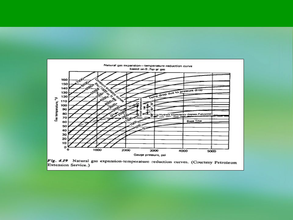
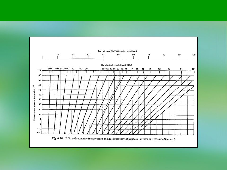
Gas flow rate 10.0 MMscfd Operating pressure 800 psig Condensate recovery 200 bbl/day Separator temperature 85°F What additional recovery could be expected using a low-temperature separation unit operating at 20°F? Solution 200 bbl/day Liquid flow rate = = 20 b/MMscf 10.0 MMscfd From Fig. 4.20, following the dotted lines, the recovery would go from 20 bbl/MMcf to 25.7 bbl/MMcf, or an additional 5.7 bbl/MMscf = 57 bbl/day.

Similar presentations