Download presentation
Presentation is loading. Please wait.

1
WELCOME IN SEM II

2
ASST. PROF. BHARAT CHAUDHARI

3
DESIGN MANUFACTURING THERMAL

4
Machine elements, Power Transmission Devices [16 Marks] UNIT NO.I INTRODUCTION TO MECHANICAL ENGINEERING
![Machine elements, Power Transmission Devices [16 Marks] UNIT NO.I INTRODUCTION TO MECHANICAL ENGINEERING](http://images.slideplayer.com/17/5385131/slides/slide_4.jpg "Machine elements, Power Transmission Devices [16 Marks] UNIT NO.I INTRODUCTION TO MECHANICAL ENGINEERING")
5
UNIT I INTRODUCTION TO MECHANICAL ENGINEERING Mechanical Elements Function, Sketch, Description & Uses of – Shaft Axle Keys ( Parallel Keys ) Coupling ( Rigid Flanged Coupling ) Bearing ( Ball Bearing ) Clutch ( Single Plate Clutch ) Brake ( Disc Brake ) Power Transmission Devices Construction, Working, Comparison & Applications of – Belt Drive ( Flat & V Belt ) Chain Drive Spur gear drive arranged with simple gear train
 Coupling ( Rigid Flanged Coupling ) Bearing ( Ball Bearing ) Clutch ( Single Plate Clutch ) Brake ( Disc Brake ) Power Transmission Devices Construction, Working, Comparison & Applications of – Belt Drive ( Flat & V Belt ) Chain Drive Spur gear drive arranged with simple gear train")
6
What is Machine? Introduction Machine is a device consisting of various elements arranged together, so as to perform the prescribe task to satisfy human needs. Eg: A pump-set is a machine in which the input is electrical energy, the pump-set utilizes the electrical energy to perform the prescribed task of lifting water to the desired location (output). INPUT (Source of energy) MACHINE (Arrangement of elements) OUTPUT (Prescribed Task)
. INPUT (Source of energy) MACHINE (Arrangement of elements) OUTPUT (Prescribed Task).")
7
INPUTMACHINEOUTPUT

8
Machine Elements Machine element is an individual component or a group of components of a machine which performs a specific function. Its function may be of holding the components together, to transmit power or to give supports. Depending upon these functions only, the machine elements are following types. 1) Machine elements used for holding the components. 2) Machine elements used for transmitting the power. 3) Machine elements used for support of other components.
 Machine elements used for holding the components. 2) Machine elements used for transmitting the power. 3) Machine elements used for support of other components..")
9
Machine elements Holding elements Supporting elements Power transmitting elements

10
Machine Elements Machine elements used for holding the components :- These type of machine elements include nuts and bolts, screw, cotters, keys, couplings, pins, revettes. Machine elements used for transmitting the power :- Machine elements like gears, shafts, clutches and brakes, pulleys, belts, chain, sprocket, are used to transmit power from one place to another. Machine elements used for support of other components:- Machine elements like bearings, axles, brackets, hangers etc. are used to give support to rotating or stationary members.

11
MECHANICAL SYSTEM MACHINE SHAFT BEARING KEYS PRIME MOVER COUPLING COUNTER SHAFT GEAR SPINDLE MACHINE TOOL WORK PIECEBASE PULLEY 1 PULLEY 2 BELT CLUTCH MAIN SHAFT

12
Shaft Introduction A shaft is a rotating member/machine element, which is used to transmit power from one place to another. In order to transfer the power from one shaft to another the various members such as pulleys, gears, crank etc. are mounted on it. These members are mounted on the shaft by means of keys or splines.

14
Types of shafts 1. Transmission 2. Machine shafts Used to transmit the power between the source and the machine 1.Line shaft 2.Counter shaft It is short rotating shaft which forms an integral part of the machine. 1.Spindle 2.crankshaft

15
Axles It is non-rotating machine element which is used to support rotating machine elements like : wheels, pulleys etc.

16
Sr. No.ShaftAxle 1Rotating memberNon-Rotating member 2Used to transmit the torque and support the transmission elements, like: gears, pulleys Only used to support the transmission elements, like: wheels, pulleys etc 3It is subject to torque, bending moment and axial force It is subjected to bending moment and axial force 4Example- line shaft, counter shaft, spindle, crankshaft Example:- front axle of car, wheel axle of motorcycle etc.

17
Types of Shafts Types :- 1) Axle An axle is stationary shaft i.e. non rotating member, which supports a rotating element like wheel or hoisting drum and fitted to the housing by means of bearings. Axle is subjected to bending load only and does not transmit any useful torque. e.g. rear axle of railway wagon axle of motor car supporting wheels. A ) Machine shaft: These shafts form an integral part of the machine itself. e.g. crank shaft of an I.C. engine.
 Machine shaft: These shafts form an integral part of the machine itself. e.g. crank shaft of an I.C. engine..")
18
Types :- 2) Spindle: A spindle is a short rotating shaft. Spindles are used in all machine tools to give motion to a cutting tool or to a work piece. e.g. spindle of drilling machine. drive shaft of lathe.

19
Types of Shafts Types :- 1) Main shaft It is a primary shaft, which is driven by the machine shaft and from which the power is supplied to the counter shaft. 2) Countershaft It is a secondary shaft, which is driven by the main shaft and from which the power is supplied to the machine components. B) Transmission shaft: These shafts transmit power from the source of power to the machine which absorbs that power. e.g. the power is transmitted from motor to compressor by means of a transmission shaft. The transmission shaft is usually circular in cross section. The shaft is always stepped (having different cross sections of shafts) for positioning transmission elements like gears, pulleys and bearings. Transmission shafts may be solid or hollow.
 Countershaft It is a secondary shaft, which is driven by the main shaft and from which the power is supplied to the machine components. B) Transmission shaft: These shafts transmit power from the source of power to the machine which absorbs that power. e.g. the power is transmitted from motor to compressor by means of a transmission shaft. The transmission shaft is usually circular in cross section. The shaft is always stepped (having different cross sections of shafts) for positioning transmission elements like gears, pulleys and bearings. Transmission shafts may be solid or hollow..")
20
Types based on structure of Shafts Hollow shafts are lighter than solid shafts. They have more strength per kg weight of material compared to solid shaft. The various types of shafts are as shown in Fig. The examples of the hollow shafts are propeller shafts. Main shaft between air compressor and gas turbine in air craft engine.

21
SOLID SHAFT STEPPED SHAFT HOLLOW SHAFT

22
Shaft Material The material used for the shaft should have the following properties 1) It should have high strength. 2) It should have good machinability. 3) It should have good heat treatment properties. 4) It should have high wear resistant properties. 5) It should have sufficient hardness. 6) It should be corrosion resistant in marine or corrosive environments. 7) It should have high modulus of elasticity. The material commonly used for shaft is mild steel. The carbon steel is also used where strength, wear resistance and facility of heat treatment is needed. The steels are designated as C40, C50, C60 etc. (that means carbon percentage in the steel is 0.40, 0.50 and 0.60 respectively.) For greater strength alloy steels such as nickel steel, nickel-chromium steel and molybdenum steel are used.
 It should have good machinability. 3) It should have good heat treatment properties. 4) It should have high wear resistant properties. 5) It should have sufficient hardness. 6) It should be corrosion resistant in marine or corrosive environments. 7) It should have high modulus of elasticity. The material commonly used for shaft is mild steel. The carbon steel is also used where strength, wear resistance and facility of heat treatment is needed. The steels are designated as C40, C50, C60 etc. (that means carbon percentage in the steel is 0.40, 0.50 and 0.60 respectively.) For greater strength alloy steels such as nickel steel, nickel-chromium steel and molybdenum steel are used..")
23
Summary Machine element is an individual component or a group of components of a machine which performs a specific function. Machine elements are used for holding the components, for transmitting the power, for the support of other component. A shaft is a rotating member or machine element, which is used to transmit power from one place to another. Shafts are classified as i) Machine shaft ii) Transmission shaft Review Questions 1) State the various functions of machine elements, with application. 2) What are the d material properties of shaft ? 3) Give the types of shafts with their application. 4) Differentiate between transmission shaft and axle.
 Machine shaft ii) Transmission shaft Review Questions 1) State the various functions of machine elements, with application. 2) What are the d material properties of shaft . 3) Give the types of shafts with their application. 4) Differentiate between transmission shaft and axle..")
24
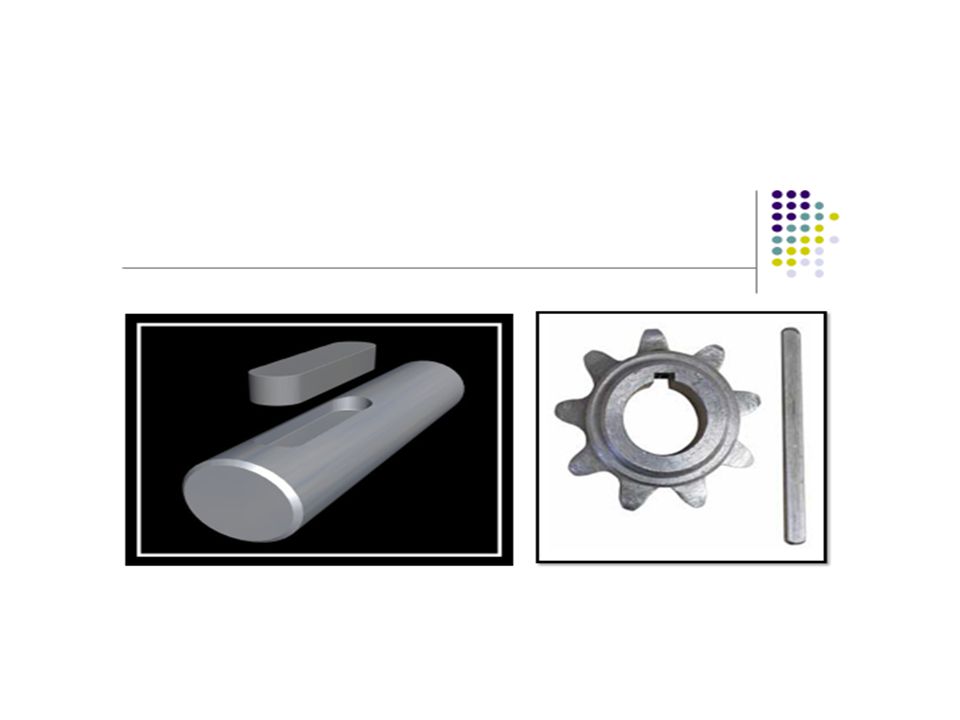
Keys A key is a machine element used on shafts to secure the rotating elements like gears, pulleys or sprockets and prevent the relative motion between the two. It is always inserted parallel to the axis of the shaft. Keys are used as temporary fastenings and are subjected to considerable crushing and shearing stresses. A keyway is a slot or recess in a shaft and hub of the pulley to accommodate a key. Materials used: Plain carbon steels Alloy steels

25
A key performs following two basic functions. 1) The primary function of key is to transmit the torque from the shaft to the hub of machine element and vice-versa. 2) The second function of the key is to prevent relative rotational motion between the shaft and mounted machine element like gear or pulley. In most of the cases, key also prevents axial motion between the elements. A keyed joint consisting of shaft, hub and key is illustrated in Fig. A recess or slot machined on the shaft and or in the hub to accommodate the key is called as key way. One key way is usually cut by milling machine. Keys are designed in order to withstand shear and compressive stresses resulting from transmission of torque. Generally, material of the key is selected, which has less strength than the shaft material.
 The primary function of key is to transmit the torque from the shaft to the hub of machine element and vice-versa. 2) The second function of the key is to prevent relative rotational motion between the shaft and mounted machine element like gear or pulley. In most of the cases, key also prevents axial motion between the elements. A keyed joint consisting of shaft, hub and key is illustrated in Fig. A recess or slot machined on the shaft and or in the hub to accommodate the key is called as key way. One key way is usually cut by milling machine. Keys are designed in order to withstand shear and compressive stresses resulting from transmission of torque. Generally, material of the key is selected, which has less strength than the shaft material..")
26
Types of Keys Keys are broadly classified as a) Saddle keys b) Sunk keys c) Round key d) Splines
 Saddle keys b) Sunk keys c) Round key d) Splines")
27
Keys

29
Parallel key Parallel keys are the most widely used. They have a square or rectangular cross-section. Square keys are used for smaller shafts and rectangular faced keys are used for shaft diameters over 6.5 in SS- 410 & SS- 316 material used in automobile industries, Textile Industries, machine tool industries, Motor & pump Industries, Cement Industries etc

31
Saddle Keys Saddle keys are fitted only in the key way of one member of the mating surface i.e. either shaft or hub. Saddle keys are only of uniform width, and tapered in thickness along the length. Power transmission of the saddle key is due to the frictional forces set up between the keys and the shaft. Saddle keys are of two types - i) Flat saddle key ii) Hollow saddle key
 Flat saddle key ii) Hollow saddle key.")
32
Flat Saddle Key The flat saddle key is a taper key which fits in a key way in the hub and is flat on the shaft as shown in Fig.

33
Hollow Saddle Key A hollow saddle key is a taper key which fits in a key way in the hub and its lower surface of the key is hollow or curved to fit on the curved surface of the shaft as shown in Fig.

34
Advantages of Saddle Keys 1) Construction is simple. 2) Mounting cost is less as compared to other keys as there is key way on the hub only. 3) No weakning of shaft as there is no key way. Disadvantages of Saddle Keys 1) Used for transmission of lighter loads only. 2) No positive transmission of power as means of power transmission in friction. Applications Used for light loads only like temporary fastening in fixing and setting of eccentric cams etc.
 Mounting cost is less as compared to other keys as there is key way on the hub only. 3) No weakning of shaft as there is no key way. Disadvantages of Saddle Keys 1) Used for transmission of lighter loads only. 2) No positive transmission of power as means of power transmission in friction. Applications Used for light loads only like temporary fastening in fixing and setting of eccentric cams etc..")
35
Sunk Keys Sunk keys are inserted half in the key way of hub and half in the key way of the shaft. Sunk keys are of uniform width and tapered in thickness along the length. Power transmission of the sunk key is due to the tangential force between key and mating surfaces. Due to the key inserted between key ways in both hub and the shaft there is no relative motion between the shaft and hub. Thus there is no slip between them. Hence it is a positive drive. Sunk keys are of following types. i) Parallel sunk key ii) Taper sunk key iii) Feather key iv) Woodruff key
 Parallel sunk key ii) Taper sunk key iii) Feather key iv) Woodruff key.")
36
Parallel SunkKey A parallel key is square or rectangular in cross section and of uniform thickness and width over its length. Parallel sunk keys with rectangular and square cross section is shown in Figs.

37
Gib Headed Key The gib head keys are ordinary sunk keys tapered on top with a raised head on one side so that its removal is easy. This is shown in figure.

38
Feather Key Some feather key arrangements are shown in figure. A feather key is used when one component slides over another. The key may be fastened either to the hub or the shaft and the keyway usually has a sliding fit.

39
Woodruff Key A woodruff key is a form of sunk key where the key shape is that of a truncated disc, as shown in figure. It is usually used for shafts less than about 60 mm diameter and the keyway is cut in the shaft using a milling cutter. It is widely used in machine tools and automobiles due to the extra advantage derived from the extra depth.

41
THANK U

Similar presentations


 24 th Oct (Wed) and 31 st Oct (Wed) 11am – 11:55am.>")
, which transmits power and rotational motion. Machine.>")


 Springs: Helical and leaf springs – Springs in series and parallel.>")


 transmits the drive from the differential sun wheel to the rear hub. The arrangement of a simple rear axle can be seen in.>")