Download presentation
Presentation is loading. Please wait.

1
Copyright 2008, Jeffrey Shotwell
Unless otherwise noted, the content of this course material is licensed under a Creative Commons Attribution 3.0 License. Copyright 2008, Jeffrey Shotwell The following information is intended to inform and educate and is not a tool for self-diagnosis or a replacement for medical evaluation, advice, diagnosis or treatment by a healthcare professional. You should speak to your physician or make an appointment to be seen if you have questions or concerns about this information or your medical condition. You assume all responsibility for use and potential liability associated with any use of the material. Material contains copyrighted content, used in accordance with U.S. law. Copyright holders of content included in this material should contact with any questions, corrections, or clarifications regarding the use of content. The Regents of the University of Michigan do not license the use of third party content posted to this site unless such a license is specifically granted in connection with particular content objects. Users of content are responsible for their compliance with applicable law.

2
Rotational Path Concepts
Images from Krol, A.J., Jacobson, T.E., & Finzen, F.C. (1999). Removable Partial Denture Design: Outline Syllabus (5th ed). San Rafael, CA : Indent ; San Francisco, CA : Bookstore, University of the Pacific, School of Dentistry, [distributor] and used with permission of the authors. Used with permission from Krol, et al.
. Removable Partial Denture Design: Outline Syllabus (5th ed). San Rafael, CA : Indent ; San Francisco, CA : Bookstore, University of the Pacific, School of Dentistry, [distributor] and used with permission of the authors. Used with permission from Krol, et al.")
3
Disclaimer: Mentions of specific products in these slides represent the opinion of the speaker only and do not represent endorsement by the University of Michigan.

4
General Considerations with Rotational Path RPDs
All rests do not seat simultaneously. It is not a straight path of placement. Eliminates unesthetic clasps. Clasps replaced by rigid retainers. Rigid retainers engage undercuts. Little tolerance for error. Krol 5th ed.

5
Linear Path of Insertion
Undercuts must exist perpendicular to the plane of occlusion

6
Linear Path of Insertion
Used with permission from Krol, et al. Curvilinear Path of Insertion Krol 5th ed. Used with permission from Krol, et al.

7
In Linear placement, all rest seat simultaneously
Used with permission from Krol, et al. Krol 5th ed. Used with permission from Krol, et al.

8
In a curvilinear path, the rests that determine the rotational axis are placed first then the RPD is rotated to final seating. Used with permission from Krol, et al. Krol 5th ed. Used with permission from Krol, et al.

9
Types of Rotational Path RPDs
Anteroposterior - Front to back Posteroanterior - Back to front Lateral - Sideways Krol 5th ed.

10
Anteroposterior Class IV Class III Krol 5th ed.
Used with permission from Krol, et al. Used with permission from Krol, et al. Class IV Class III Krol 5th ed.

11
Posteroanterior Class III Krol 5th ed.
Used with permission from Krol, et al. Used with permission from Krol, et al. Class III Krol 5th ed.

12
Lateral Used with permission from Krol, et al. Class III Krol 5th ed.

13
Categories of Rotational Path RPDs
Category I - The rotational centers (rests) are seated first then the prosthesis is rotated into place. Category II - (Dual Path) The rotational centers are located at the gingival extension of the rigid retainers Krol 5th ed.
 are seated first then the prosthesis is rotated into place. Category II - (Dual Path) The rotational centers are located at the gingival extension of the rigid retainers. Krol 5th ed.")
14
Category I Krol 5th ed. Used with permission from Krol, et al.

15
Category II Slight space created Krol 5th ed.
Used with permission from Krol, et al. Used with permission from Krol, et al. Slight space created Krol 5th ed. Used with permission from Krol, et al.

16
Cast Analysis Plane of occlusion Length of the edentulous span
Rotational axis Shape of the dental arch Depth of undercut

17
Plane of Occlusion affects the depth of undercut
Used with permission from Krol, et al. Used with permission from Krol, et al.

18
Length of the edentulous span
Used with permission from Krol, et al. Used with permission from Krol, et al. The closer the edentulous area is to the rotational axis the greater the blockout Krol 5th ed.

19
Position of the rotational axis
Will effect the placement of the prosthesis

20
Will effect the amount of blockout
The shape of the arch Used with permission from Krol, et al. Will effect the amount of blockout Krol 5th ed.

21
Depth of undercut Krol 5th ed. Used with permission from Krol, et al.

22
Surveying Anterior tilt 0 degree tilt Krol 5th ed.
Used with permission from Krol, et al. Used with permission from Krol, et al. Anterior tilt 0 degree tilt Krol 5th ed.

23
Rest preparations Posterior Anterior Krol 5th ed.
Used with permission from Krol, et al. Used with permission from Krol, et al. Posterior Anterior Krol 5th ed.

24
Rest preparations Anterior Posterior Krol 5th ed.
Used with permission from Krol, et al. Posterior Used with permission from Krol, et al. Krol 5th ed.

25
Guide plane preparations
Used with permission from Krol, et al. Used with permission from Krol, et al. Used with permission from Krol, et al. Guide planes are curvilinear Krol 5th ed.

26
Patient presentations
Posteroanterior (Category I) Anteroposterior (Category II) Anteroposterior (Category I) Lateral (Category II) Lateral (Category I)
 Anteroposterior (Category II) Anteroposterior (Category I) Lateral (Category II) Lateral (Category I)")
27
Posteroanterior Category I Krol 5th ed.
Used with permission from Krol, et al. Used with permission from Krol, et al. Krol 5th ed.

28
Posteroanterior Category I Axis of Rotation

29
The shorter the span the greater the blockout
Posteroanterior Category I The shorter the span the greater the blockout

30
Posteroanterior Category I

31
Anteroposterior Category II Krol 5th ed.
Used with permission from Krol, et al. Krol 5th ed.

32
Anteroposterior Category II Maxillary Mandibular

33
Radiographic Evaluation
Anteroposterior Category II Radiographic Evaluation

34
Anteroposterior Category II Crown Fabrication Try-in

35
Anteroposterior Category II Final Result

36
Anteroposterior Category I Krol 5th ed.
Used with permission from Krol, et al. Krol 5th ed.

37
Anteroposterior Category I

38
Anteroposterior Category I

39
Lateral Category II Krol 5th ed.
Used with permission from Krol, et al. Krol 5th ed.

40
Lateral Category II

41
Lateral Category II

42
Lateral Category II Framework Design

43
Lateral Category II

44
Lateral Category II Try-in

45
Lateral Category II

46
Lateral Category II Final Result

47
Lateral Category I Rotational Axis

48
Lateral Category I

49
Lateral Category I

50
Lateral Category I

51
Lateral Category I Final Result

52
Swinglock Removable Partial Denture Treatment

53
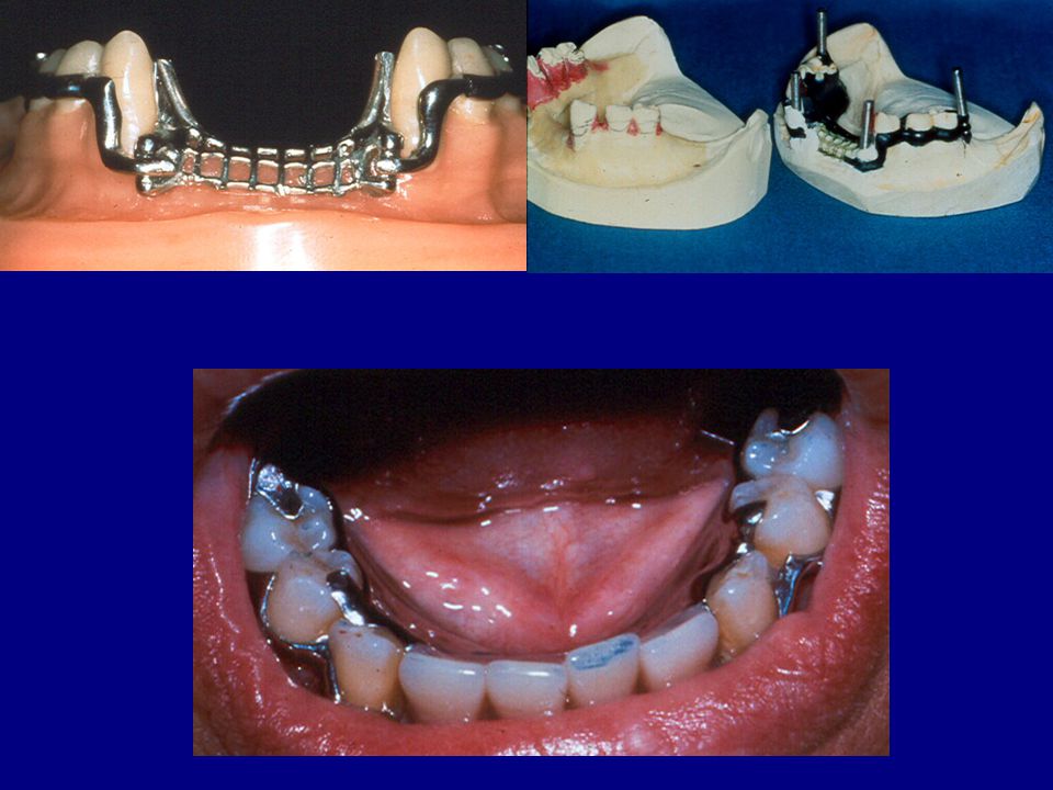
Though less expensive than implants, this type of framework is significantly more expensive from the dental laboratory. Typically the cost will be $200-$250 more than a conventional framework. Looking at the intraoral view at the right, could other options have been used? Six anterior teeth with slight to moderate crowding.

54
This is another example of a patient situation that may be suited for a swinglock RPD. Here again, are there other designs which would work?

55
This acrylic cast was duplicated from an actual patient treatment model to demonstrate the fabrication of a swinglock RPD framework.

56
Block out between the lower anterior teeth to prevent tearing and distortion of the duplicating material used to duplicate the master cast in an investment material 24 gauge wax over the posterior edentulous areas and left with a sharp demarcation at the anterior aspect of the block out The block out of the master cast (normally done on an improved stone cast)
")
57
The blocked out cast ready for duplication
The blocked out cast ready for duplication. Remember, this would usually be done on a cast poured in improved stone (Jade Stone or another Die Stone) These examples provide a better example for the sake of this presentation.
 These examples provide a better example for the sake of this presentation.")
58
The framework design is drawn on a study cast to guide the laboratory with the fabrication of the framework.

59
The wax up of the framework seen here is performed on a cast made of refractory material not dental stone. This is a duplicate of the blocked out master cast.

60
Once the wax up is completed, it is surrounded by more refractory material, placed in a burn out oven and cast in a Cr-Co alloy. After finishing, you have the polished framework seen at the right.

61
Hinge Side Gate Side Framework on master cast ready for the addition of temporary bases, try in with the patient and securing an interocclusal bite registration

62
This view shows why lack of vestibular depth is a problem with this type of appliance. Also, you want to see if the patient is right or left handed when determining which side to put the hinge on. Why?

63
A clinical example. Note how the hinge and gate are held back from the anterior teeth to allow room for the components. Why not place them immediately adjacent to the anterior teeth?

64
Gate Side Hinge Side Completed Treatment

65
Further Examples Of Class I Swinglock RPD’s

66
In this patient, the remaining anterior teeth are both labially tilted and #22 and #27 are rotated. If these teeth were to be recontoured to make a conventional clasp partial possible, there would need to be extensive reshaping of #22. Due to the labial tilt and the rotation of the potential abutment teeth, a swing lock partial may be desirable here.

67
As you can see, the swing lock gate has “fingers” which contact the labial surfaces of the anterior teeth. Most are in the configuration of an I bar and the finger on #27 is in the shape of a modified T bar clasp.

68
Upper complete denture for the patient
Upper complete denture for the patient. Note the plane of occlusion of the upper appliance. Fairly level and oriented from the anterior teeth to the approximate center of the retromolar pad in an A-P direction.

69
Note that the fingers on the gate have similar shapes to the previous appliance reviewed. The side of the RPD which has the hinge should be reviewed with the patient depending on their ability to reach and manipulate the gate side of the appliance.

70
As you can see, the patient in full smile does not display the labial aspect of the lower removable partial denture.

71
Anterior Modification Space with the Swinglock RPD
Kennedy IA Anterior Modification Space with the Swinglock RPD

72
Alternate design thoughts
Alternate design thoughts? As viewed from above and from the labial, could this appliance have been a conventional clasp design?

73
The same question as the previous image, could this patient have been treated with a conventional clasp RPD? Thoughts either way. Is there a “right” or “wrong” answer?

74
Treating this case may be more challenging
Treating this case may be more challenging. Could we design a clasp type RPD for this patient? Kennedy class II

75
The actual wax up of the framework on the refractory model.

76
The image at the left shows the framework at the wax try in stage and below is the finished RPD.

77
Kennedy IIP Another example showing a posterior modification space with a class II lower RPD. Here again, could other designs have been utilized?

78
Kennedy IV

80
Questions ???????

Similar presentations