Download presentation
Presentation is loading. Please wait.

1
Communication Chapter 2

2
Communication Due to the absence of shared memory, all communication in distributed systems in based on exchanging messages over an unreliable network such as the Internet. Unless the primitive communication facilities of computer networks are replaced by something else, development of large-scale distributed applications is extremely difficult.

3
Communication Four widely-used modes for communications are discussed in this chapter: –Remote Procedure Call (RPC) –Remote Method Invocation (RMI) –Message-Oriented Middleware (MOM) –Streams
 –Remote Method Invocation (RMI) –Message-Oriented Middleware (MOM) –Streams")
4
Layered Protocols International Standards Organization (ISO) develop Open Systems Interconnection (OSI) Reference Model as the standard for networks. The protocol is a well-known set of rules and formats used for communication. The protocols developed as part of the OSI model never widely used. However, the underlying model has proved to be quite useful for understanding computer networks.

5
Layered Protocols With connection-oriented protocols, the sender and receiver must establish connection before communication. –Example: telephone With connectionless protocols, no setup in advance is needed. –Example: postal service In the OSI model, communication is divided up into seven levels of layers.

6
Layered Protocols Layers, interfaces, and protocols in the OSI model. 2-1

7
Application Presentation Session Transport End host One or more nodes Network Data link Physical Network Data link Physical Network Data link Physical Application Presentation Session Transport End host Network Data link Physical within the network ISO 7-Layer Reference Model Unreliable transmission (tx) of raw bits Reliable transmission (tx) of frames Unreliable end-to-end tx of packets Reliable, end-to-end byte stream (TCP) Provide session semantics (RPC) Present data in a meaningful format Various applications (FTP,HTTP,…)
 of raw bits Reliable transmission (tx) of frames Unreliable end-to-end tx of packets Reliable, end-to-end byte stream (TCP) Provide session semantics (RPC) Present data in a meaningful format Various applications (FTP,HTTP,…)")
8
Layered Protocols A typical message as it appears on the network. 2-2

9
Layered Protocols Each protocol layer has two different interfaces –service interface: operations defined to serve the upper layer. –peer-to-peer interface: messages exchanged with peer Each layer adds a header or tail to the message and transmits it to the lower layer. The message is then passed upward, with each layer stripping off those added headers or tails. The collection of protocols used in a particular system is called a protocol suite/stack. The TCP/IP suite developed for the Internet is widely used.

10
OSI 7 Layer Reference Model Physical - transmission of raw bits over a communication channel, e.g. RS-232-C Data Link - reliable transmission of a block of data (frame) Put as special bit pattern on the start and end of each frame. Compute a checksum by adding up all the bytes in the frame.
 Put as special bit pattern on the start and end of each frame. Compute a checksum by adding up all the bytes in the frame..")
11
Data Link Layer Discussion between a receiver and a sender in the data link layer. 2-3

12
OSI 7 Layer Reference Model Network - describes how packets in a network of computers are to be routed. IP (Internet Protocol) is a connectionless protocol. The virtual channel in ATM (asynchronous transfer mode) is a connection-oriented network layer protocol.
 is a connectionless protocol. The virtual channel in ATM (asynchronous transfer mode) is a connection-oriented network layer protocol..")
13
OSI 7 Layer Reference Model Transport - logical communication channel between processes (message) TCP (Transmission Control Protocol): connection- oriented, reliable, stream-oriented communication. UDP (Universal Datagram Protocol): connection-less unreliable (best-effort) datagram communication. TCP for transactions (T/TCP): A TCP protocol combines setting up a connection with immediately sending the request, and sending an answer with closing the connection. RTP (Real-time Transport Protocol) is used to support real-time data transfer.
: connection-less unreliable (best-effort) datagram communication. TCP for transactions (T/TCP): A TCP protocol combines setting up a connection with immediately sending the request, and sending an answer with closing the connection. RTP (Real-time Transport Protocol) is used to support real-time data transfer..")
14
Client-Server TCP a)Normal operation of TCP. b)Transactional TCP. 2-4
Normal operation of TCP. b)Transactional TCP. 2-4")
15
OSI 7 Layer Reference Model Session - dialog control between end applications Presentation - data format translation Application – e.g. ftp, telnet, Web browser, and etc. FTP (File Transfer Protocol) HTTP (HyperText Transfer Protocol)
 HTTP (HyperText Transfer Protocol).")
16
OSI protocol summary LayerDescriptionExamples ApplicationProtocols that are designed to meet the communication requirements of specific applications, often defining the interface to a service. HTTP, FTP,SMTP, CORBA IIOP PresentationProtocols at this level transmit data in a network representation that is independent of the representations used in individual computers, which may differ. Encryption is also performed in this layer, if required. Secure Sockets (SSL),CORBA Data Rep. SessionAt this level reliability and adaptation are performed, such as detection of failures and automatic recovery. TransportThis is the lowest level at which messages (rather than packets) are handled. Messages are addressed to communication ports attached to processes, Protocols in this layer may be connection-oriented or connectionless. TCP,UDP NetworkTransfers data packets between computers in a specific network. In a WAN or an internetwork this involves the generation of a route passing through routers. In a single LAN no routing is required. IP,ATM virtual circuits Data linkResponsible for transmission of packets between nodes that are directly connected by a physical link. In a WAN transmission is between pairs of routers or between routers and hosts. In a LAN it is between any pair of hosts. Ethernet MAC, ATM cell transfer, PPP PhysicalThe circuits and hardware that drive the network. It transmits sequences of binary data by analogue signalling, using amplitude or frequency modulation of electrical signals (on cable circuits), light signals (on fibre optic circuits) or other electromagnetic signals (on radio and microwave circuits). Ethernet base- band signalling,ISDN
,CORBA Data Rep. SessionAt this level reliability and adaptation are performed, such as detection of failures and automatic recovery. TransportThis is the lowest level at which messages (rather than packets) are handled. Messages are addressed to communication ports attached to processes, Protocols in this layer may be connection-oriented or connectionless. TCP,UDP NetworkTransfers data packets between computers in a specific network. In a WAN or an internetwork this involves the generation of a route passing through routers. In a single LAN no routing is required. IP,ATM virtual circuits Data linkResponsible for transmission of packets between nodes that are directly connected by a physical link. In a WAN transmission is between pairs of routers or between routers and hosts. In a LAN it is between any pair of hosts. Ethernet MAC, ATM cell transfer, PPP PhysicalThe circuits and hardware that drive the network. It transmits sequences of binary data by analogue signalling, using amplitude or frequency modulation of electrical signals (on cable circuits), light signals (on fibre optic circuits) or other electromagnetic signals (on radio and microwave circuits). Ethernet base- band signalling,ISDN.")
17
OSI Model vs. Internet Protocol Suit Why do both sockets and XTI (X/Open Transport Interface) provide the interface from the upper three layers of the OSI model into the transport layer? –First, the upper three layers handle all the details of the application and The lower four layers handle all the communication details. –Second, the upper three layers is called a user process while the lower four layers are provided as part of the operating system kernel. Application Session Presentation Transport Network Datalink Physical 76543217654321 OSI Model Application TCP | | UDP IPv4, IPv6 Device driver and Hardware Internet protocol suite Sockets XTI user process kernel application details communication details Figure Layers on OSI model and Internet protocol suite
 provide the interface from the upper three layers of the OSI model into the transport layer. –First, the upper three layers handle all the details of the application and The lower four layers handle all the communication details. –Second, the upper three layers is called a user process while the lower four layers are provided as part of the operating system kernel. Application Session Presentation Transport Network Datalink Physical OSI Model Application TCP | | UDP IPv4, IPv6 Device driver and Hardware Internet protocol suite Sockets XTI user process kernel application details communication details Figure Layers on OSI model and Internet protocol suite.")
18
The Big Picture

19
Common Internet Protocols IPv4 (Internet Protocol, version 4) IPv6 (Internet Protocol, version 6) TCP (Transmission Control Protocol) UDP (User Datagram Protocol) ICMP (Internet Control Message Protocol) IGMP (Internet Group Management Protocol) is used with multicasting. ARP (Address Resolution Protocol) RARP (Reverse Address Resolution Protocol) ICMPv6 (Internet Control Message Protocol, version 6) combines the functionality of ICMPv4, IGMP, and ARP. BPF (BSD Packet Filter) is a datalink layer interface for Berkeley-based kernels. DLPI (Data Link Provider Interface) is a datalink layer interface for SVR4-based kernels.
 RARP (Reverse Address Resolution Protocol) ICMPv6 (Internet Control Message Protocol, version 6) combines the functionality of ICMPv4, IGMP, and ARP. BPF (BSD Packet Filter) is a datalink layer interface for Berkeley-based kernels. DLPI (Data Link Provider Interface) is a datalink layer interface for SVR4-based kernels..")
20
Port Numbers

21
TCP port Numbers and Concurrent Servers

23
Common Internet Applications OSPF (routing) - Open Shortest Path First RIP (routing) - Routing Information Protocol) BGP (routing) – Border Gateway Protocol SMTP (email) – Simple Mail Transfer Protocol POP (email) – Post Office Protocol Telnet (remote login) SSH (remote login) – Secure Shell FTP (file transfer) – File Transfer Protocl HTTP (web) – HyperText Transfer Protocol NNTP (netnews) - Network News Transfer Protocol NTP (time) – Network Time Protocol DNS (name service) – Domain Name Service NFS (distributed file system) – Network File System Sun RPC (remote procedure call) DCE RPC (remote procedure call)
 - Open Shortest Path First RIP (routing) - Routing Information Protocol) BGP (routing) – Border Gateway Protocol SMTP ( ) – Simple Mail Transfer Protocol POP ( ) – Post Office Protocol Telnet (remote login) SSH (remote login) – Secure Shell FTP (file transfer) – File Transfer Protocl HTTP (web) – HyperText Transfer Protocol NNTP (netnews) - Network News Transfer Protocol NTP (time) – Network Time Protocol DNS (name service) – Domain Name Service NFS (distributed file system) – Network File System Sun RPC (remote procedure call) DCE RPC (remote procedure call)")
24
Protocol usage by common internet Application

25
Middleware Layer Observation: Middleware is invented to provide common services and protocols that can be used by many different applications: – A rich set of communication protocols, but which allow different applications to communicate –Marshaling and unmarshaling of data, necessary for integrated systems –Naming protocols, so that different applications can easily share resources –Security protocols, to allow different applications to communicate in a secure way –Scaling mechanisms, such as support for replication and caching

26
Middleware Protocols An adapted reference model for networked communication. 2-5

27
Remote Procedure Call - Basics The basic paradigm for communication is I/O - read and write = message passing. Observations: –Application developers are familiar with simple procedure model –Well-engineered procedures operate in isolation (black box) –There is no fundamental reason not to execute procedures on separate machine Why not allow those paradigms available in a centralized system - procedure calls, shared memory, etc.
 –There is no fundamental reason not to execute procedures on separate machine Why not allow those paradigms available in a centralized system - procedure calls, shared memory, etc..")
28
Basic RPC - Conventional Procedure Call Local procedure call: read(int fd, char* buf, int nbytes) 1.Push parameter values of the procedure on a stack 2.Call procedure 3.Use stack for local variables 4.Pop results (in parameters) Principle: communication with local procedure is handled by copying data to/from the stack (with a few exceptions)
 1.Push parameter values of the procedure on a stack 2.Call procedure 3.Use stack for local variables 4.Pop results (in parameters) Principle: communication with local procedure is handled by copying data to/from the stack (with a few exceptions)")
29
Conventional Procedure Call a)Parameter passing in a local procedure call: the stack before the call to read b)The stack while the called procedure is active
Parameter passing in a local procedure call: the stack before the call to read b)The stack while the called procedure is active")
30
Remote Procedure Call Parameter Passing mechanisms: 1. Call-by-value C 2. Call-by-reference var parameters in Pascal 3. Call-by-copy/restore ADA in/out parameters Note about call-by-copy/restore: –The restored value depends on the pushing sequence of the stack. –In C, the last parameter is pushed first and last restored. In Pascal, the first parameter is pushed first and last restored.

31
Conventional Procedure Call Example int double(x,y) { x = x + 1; y = y + 1; return (x + y); } main() { int a,b; a = 0; b = double(a,a); printf("a = %d, b= %d \n", a, b); }
 { x = x + 1; y = y + 1; return (x + y); } main() { int a,b; a = 0; b = double(a,a); printf( a = %d, b= %d \n , a, b); }")
32
Conventional Procedure Call Parameter Passing: Printed: 1. Call-by-value a=0 b=2 2. Call-by-reference a=2 b=4 3. Call-by-copy/restore a=1 b=2 A revision of the previous example in the copy/restore case (initially, a = 0): int double(x, y) { x = x + 1; y = y + 2; return (x + y); } –C semantics: the first pushed/last restored value of a is the value of y, that is 2. –Pascal sematics: the fist pushed/last restored value of a is the value of x, that is 1.
: int double(x, y) { x = x + 1; y = y + 2; return (x + y); } –C semantics: the first pushed/last restored value of a is the value of y, that is 2. –Pascal sematics: the fist pushed/last restored value of a is the value of x, that is 1..")
33
Remote Procedure Call Remote Procedure Call (RPC) is a protocol that allows programs to call procedures located on other machines. RPC uses the client/server model. The requesting program is a client and the service-providing program is the server. The client stub acts as a proxy for the remote procedure. The server stub acts as a correspondent to the client stub.

34
Client and Server Stubs Principle of RPC between a client and server program.

35
Steps of a Remote Procedure Call 1.Client procedure calls client stub in normal way 2.Client stub builds message, calls local OS 3.Client's OS sends message to remote OS 4.Remote OS gives message to server stub 5.Server stub unpacks parameters, calls server 6.Server does work, returns result to the stub 7.Server stub packs it in message, calls local OS 8.Server's OS sends message to client's OS 9.Client's OS gives message to client stub 10.Stub unpacks result, returns to client

36
Steps of a Remote Procedure Call

37
Passing Value Parameters Steps involved in doing remote computation through RPC 2-8

38
RPC: Parameter Passing Parameter marshaling: There's more than just wrapping parameters into a message: –Client and server machines may have different data representations (consider byte ordering) –Wrapping a parameter means transforming a value into a sequence of bytes –Client and server have to agree on the same encoding: How are basic data values represented (integers, floats, characters) How are complex data values represented (arrays, unions) –Client and server need to properly interpret messages, transforming them into machine-dependent representations.
 –Wrapping a parameter means transforming a value into a sequence of bytes –Client and server have to agree on the same encoding: How are basic data values represented (integers, floats, characters) How are complex data values represented (arrays, unions) –Client and server need to properly interpret messages, transforming them into machine-dependent representations.")
39
RPC: Parameter Passing RPC Parameter passing: – RPC assumes copy in/copy out semantics: while procedure is executed, nothing can be assumed about parameter values (only Ada supports this model). –RPC assumes all data that is to be operated on is passed by parameters. No passing references to (global) data. Conclusion: full access transparency cannot be realized. Observation: If we introduce a remote reference mechanism, access transparency can be enhanced: –Remote reference offers unified access to remote data –Remote references can be passed as parameter in RPCs
 data. Conclusion: full access transparency cannot be realized. Observation: If we introduce a remote reference mechanism, access transparency can be enhanced: –Remote reference offers unified access to remote data –Remote references can be passed as parameter in RPCs.")
40
Passing Value Parameters a)Original message on the Pentium (little endian) b)The message after receipt on the SPARC (big endian) c)The message after being inverted. The little numbers in boxes indicate the address of each byte

41
RPC: Passing Reference Parameter How are pointers or references passed? –Forbid pointers and reference parameters – undesirable solution –Copy and restore Enhancement: If the pointer is an input parameter or an output parameter to the server, one of the copies can be eliminated. –Some systems actually pass the pointer to the server stub and generate special code in the server procedure for using pointers. The caller and callee must agree on: the exchange message format, data representation, protocol used.

42
Parameter Specification and Stub Generation a)A procedure b)The corresponding message.
A procedure b)The corresponding message.")
43
Semantics of RPC What happens if the server crashes? The client stub should: 1. Hang forever waiting for a reply that will never come. (put burden on application programmer) 2. Time out and raise an exception or report failure to the client. 3. Time out and retransmit the request – only satisfactory if the operation is idempotent; that is, it does not matter how many times it is executed, the result is same.
 2. Time out and raise an exception or report failure to the client. 3. Time out and retransmit the request – only satisfactory if the operation is idempotent; that is, it does not matter how many times it is executed, the result is same..")
44
Semantics of RPC Exactly once- the operation is executed exactly once; if the server is unachievable, suppose the server crashes. At most once - the operation has been performed either zero or one times. At least once - the client stub tries over and over until it gets a proper reply (okay for idempotent option).
..")
45
Extended RPC Models - Door Doors are RPCs implemented for processes on the same machine. Doors are added into the system as a part of IPC facilities such as shared memory, pipes, message queues. The main benefit of doors is that they allow the use of the RPC mechanism as the only mechanism for interprocess communication (IPC) in a distributed system.
 in a distributed system..")
46
Doors The principle of using doors as IPC mechanism.

47
Extended RPC Models – Asynchronous RPC By asynchronous RPCs a client immediately continues after issuing the RPC request. This gets rid of the strict request-reply behavior. Combing two asynchronous RPCs is sometimes also referred to as a deferred synchronous RPC. One-way RPCs are referred as the client does not wait for an acknowledgement of the server’s acceptance of the request.

48
Asynchronous RPC a)The interconnection between client and server in a traditional RPC b)The interaction using asynchronous RPC 2-12
The interconnection between client and server in a traditional RPC b)The interaction using asynchronous RPC 2-12")
49
Deferred synchronous RPC A client and server interacting through two asynchronous RPCs 2-13

50
RPC in Practice - DCE RPC The Distributed Computing Environment (DCE) RPC is developed by the Open Software Foundation (OSF)/Open Group. DCE is a middleware executing as an abstraction layer between (network) operating systems and distributed applications. Microsoft derived its version of RPC from DCE RPC (e.g., M(icrosoft)IDL compiler, etc.) DCE includes the a number of services: –Distributed file service –Directory service –Security service –Distributed time service
 operating systems and distributed applications. Microsoft derived its version of RPC from DCE RPC (e.g., M(icrosoft)IDL compiler, etc.) DCE includes the a number of services: –Distributed file service –Directory service –Security service –Distributed time service.")
51
DCE RPC The goals of the DCE RPC: –The main goal is to make it possible for a client to access a remote service by simply calling a local procedure. –The IDL interface makes it possible for client programs to be written in a simple way. –The RPC system makes it easy to have large volumes of existing code run in a distributed environment with few changes.

52
DCE RPC Develop a RPC application: –Write the Interface Definition Language (IDL) that is used to specify the variables (data) and functions (methods). –Run the IDL through the RPC generator. –Write a client and a server: The developer concentrate on only the client- and server-specific code; let the RPC system (generators and libraries) do the rest (network, data exchange). –Make (compile) the client and server code. –Bind a client to a server –Perform an RPC
 do the rest (network, data exchange). –Make (compile) the client and server code. –Bind a client to a server –Perform an RPC.")
53
Interface Definition Language IDL contains function prototypes (syntax but no semantics, type definitions, constant declarations, marshalling and unmarshalling information. Every IDL has a globally unique identifier for the specified interface. After running IDL through the interface generator, three files are generated: –A header file –The client stub –The server stub

54
IDL - Example const MAX = 1000; typedef int FileIdentifier; typedef int FilePointer; typedef int Length; struct Data { int length; char buffer[MAX]; }; struct writeargs { FileIdentifier f; FilePointer position; Data data; }; struct readargs { FileIdentifier f; FilePointer position; Length length; }; program FILEREADWRITE { version VERSION { void WRITE(writeargs)=1;1 Data READ(readargs)=2;2 }=2; } = 9999;
![IDL - Example const MAX = 1000; typedef int FileIdentifier; typedef int FilePointer; typedef int Length; struct Data { int length; char buffer[MAX]; }; struct writeargs { FileIdentifier f; FilePointer position; Data data; }; struct readargs { FileIdentifier f; FilePointer position; Length length; }; program FILEREADWRITE { version VERSION { void WRITE(writeargs)=1;1 Data READ(readargs)=2;2 }=2; } = 9999;](http://images.slideplayer.com/17/5380287/slides/slide_54.jpg "IDL - Example const MAX = 1000; typedef int FileIdentifier; typedef int FilePointer; typedef int Length; struct Data { int length; char buffer[MAX]; }; struct writeargs { FileIdentifier f; FilePointer position; Data data; }; struct readargs { FileIdentifier f; FilePointer position; Length length; }; program FILEREADWRITE { version VERSION { void WRITE(writeargs)=1;1 Data READ(readargs)=2;2 }=2; } = 9999;")
55
Writing a Client and a Server The steps in writing a client and a server in DCE RPC. 2-14

56
Client-to-Server Binding (DCE RPC) Server location is done in two steps: –locate the server’s machine. –locate the server (the correct process) on that machine. Execution of Client and Server –The server registers its procedures with the portmapper. –Client must locate server machine: The client contacts the portmapper to determine which port the server is listening to. –The client communicates with the server on the assigned port. DCE uses a separate daemon for each server machine.
 on that machine. Execution of Client and Server –The server registers its procedures with the portmapper. –Client must locate server machine: The client contacts the portmapper to determine which port the server is listening to. –The client communicates with the server on the assigned port. DCE uses a separate daemon for each server machine..")
57
Binding a Client to a Server Client-to-server binding in DCE. 2-15

58
Remote Object Invocation We can expand the idea of RPCs to invocations on remote objects. The key feature of an object is that is encapsulates data, called the state, and the operations on those data, called the methods. This separation allows us to place an interface at one machine, while the object itself resides on another machine. This organization is commonly referred to as a distributed object (In Chapter 10, CORBA and DCOM will be discussed).
..")
59
Remote Object Invocation Data and operations are encapsulated in an object. Operations are implemented as methods, and are accessible through interfaces. Object offers only its interface to clients. Object server is responsible for a collection of objects. When a client binds to a distributed object, an implementation of the object’s interface, called Client stub (proxy), is loaded into the client’s address space. Server skeleton (stub) handles (un)marshaling and object invocation.
, is loaded into the client’s address space. Server skeleton (stub) handles (un)marshaling and object invocation..")
60
Distributed Objects Common organization of a remote object with client-side proxy. 2-16

61
Remote Distributed Objects Compile-time objects are language-level objects, defined as the instance of a class, from which proxy and skeletons are automatically generated (e.g. Java). –A class is a description of an abstract type in terms of a module with data elements and operations on that data. –Drawback: dependency on a specific programming language Runtime objects can be implemented in any language, but require use of an object adapter that makes the implementation appear as an object (e.g. CORBA). –An object adapter acts as a wrapper around the implementation. Persistent objects live independently from a server. If a server exits, the object's state and code remain (passively) on disk. Transient objects exist as long as a server exists. If the server exits, so will the object.
. –A class is a description of an abstract type in terms of a module with data elements and operations on that data. –Drawback: dependency on a specific programming language Runtime objects can be implemented in any language, but require use of an object adapter that makes the implementation appear as an object (e.g. CORBA). –An object adapter acts as a wrapper around the implementation. Persistent objects live independently from a server. If a server exits, the object s state and code remain (passively) on disk. Transient objects exist as long as a server exists. If the server exits, so will the object..")
62
Client-to-Object Binding Object reference (not available in RPC): Having an object reference allows a client to bind to an object: –Reference denotes server, object, and communication protocol –Client loads associated stub code –Stub is instantiated and initialized for the specific object Two ways of binding –Implicit: Invoke methods directly on the referenced object –Explicit: Client must first explicitly bind to object before invoking it
: Having an object reference allows a client to bind to an object: –Reference denotes server, object, and communication protocol –Client loads associated stub code –Stub is instantiated and initialized for the specific object Two ways of binding –Implicit: Invoke methods directly on the referenced object –Explicit: Client must first explicitly bind to object before invoking it")
63
Binding a Client to an Object a)An example with implicit binding using only global references b)An example with explicit binding using global and local references Distr_object* obj_ref;//Declare a systemwide object reference obj_ref = …;// Initialize the reference to a distributed object obj_ref-> do_something();// Implicitly bind and invoke a method (a) Distr_object objPref;//Declare a systemwide object reference Local_object* obj_ptr;//Declare a pointer to local objects obj_ref = …;//Initialize the reference to a distributed object obj_ptr = bind(obj_ref);//Explicitly bind and obtain a pointer to the local proxy obj_ptr -> do_something();//Invoke a method on the local proxy (b)
An example with implicit binding using only global references b)An example with explicit binding using global and local references Distr_object* obj_ref;//Declare a systemwide object reference obj_ref = …;// Initialize the reference to a distributed object obj_ref-> do_something();// Implicitly bind and invoke a method (a) Distr_object objPref;//Declare a systemwide object reference Local_object* obj_ptr;//Declare a pointer to local objects obj_ref = …;//Initialize the reference to a distributed object obj_ptr = bind(obj_ref);//Explicitly bind and obtain a pointer to the local proxy obj_ptr -> do_something();//Invoke a method on the local proxy (b)")
64
Client-to-Object Binding Some remarks: –A reference may contain a URL pointing to an implementation file. –The (Server, object) pair is enough to locate target object. –We need only a standard protocol for loading and instantiating code. Observation: Remote-object references allows us to pass references as parameters. This was difficult with ordinary RPCs.
 pair is enough to locate target object. –We need only a standard protocol for loading and instantiating code. Observation: Remote-object references allows us to pass references as parameters. This was difficult with ordinary RPCs..")
65
Remote Method Invocation RMI (Remote Method Invocation) allows a client to invoke a method of a remote object. It is different from RPC in the way the data marshalling and unmarshalling. Basics: Assume the client stub and server skeleton are in place. –The client invokes the method at the stub. –The stub marshals request and sends it to the server. –The server ensures referenced object is active: Create separate process to hold object. Load the object into server process. –The request is unmarshaled by the object's skeleton, and the referenced method is invoked. –If the request contained an object reference, the invocation is applied recursively. –The result is marshaled and passed back to the client. –The client stub unmarshals the reply and passes the result to the client application.

66
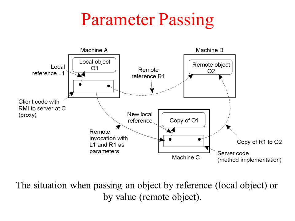
RMI: Parameter Passing Object reference is easier to be implemented in RMI than in the case of RPC. –The server can simply bind to the referenced object, and invoke methods. –Unbind when referenced object is no longer needed. Object-by-value: A client may also pass a complete object as the parameter value. –An object has to be marshaled: Marshall its state. Marshall its methods, or give a reference to where an implementation can be found. –The server unmarshals the object. Note that we have now created a copy of the original object. –Object-by-value passing tends to introduce intricate problems.

67
Parameter Passing The situation when passing an object by reference (local object) or by value (remote object). 2-18
68
The DCE Distributed-Object Model Distributed objects have been added to DCE as extensions to RPC. They are specified in IDL, and implemented in C++. Distributed objects take the form of remote objects, of which the actual implementation resides at a server. Two types of distributed objects are supported: –A distributed dynamic object is an object that a server creates locally on behalf of a client and is accessed by that client. –Distributed named objects are not intended to be associated with a specific client but are shared by several clients.

69
The DCE Distributed-Object Model a)Distributed dynamic objects in DCE. b)Distributed named objects 2-19
Distributed named objects")
70
DCE Remote Object Invocation Each remote object invocation in DCE is done by means of an RPC. –When a client invokes a method of an object, it passes identifier of object, interface, method, and parameters to the server. –The server maintains an object table from which it can derive which object is to be invoked and then dispatch the requested method with its parameters. DCE can place objects in secondary storage and keep active objects in the main memory. The problem of distributed objects in DCE is there is no mechanism for transparent object references.

71
Java Distributed-Object Model In DCE, distributed objects are added as a refinement of RPC. DCE lacks a system-wide object reference mechanism. Java adopts remote objects as the only form of distributed objects. –Objects’ state resides on one machine, but their interfaces can be made available to remote processes. –Interfaces are implemented by means of a proxy, which appears as a local object in the client.

72
Java Distributed-Object Model Remote versus local objects: –Cloning local objects makes the exact copy of the object. Cloning remote objects makes an exact copy of the object in the server. Proxies are not cloned. To access the remote cloned object, the client needs to bind to that object. –In Java, if two processes are calling a synchronized method simultaneously, only one process will proceed and the other will be blocked. The Java RMI Restrict blocking on remote objects only to the proxies.

73
Java Remote Object Invocation In Java, the object is serialized before being passed as a parameter to an RMI. –Platform-dependent objects such as file descriptors and sockets cannot be serialized. During an RMI local objects are passed by object copying whereas remote objects are passed by reference. A remote object is built from two different classes: –Server class – implementation of server-side code. –Client class – implementation of a proxy. In Java, a proxy is serializable and is used as a reference to the remote object. –It is possible to marshal a proxy and send it as a series of bytes to another process. –Passing proxies as parameters works because each process is executing in the same Java virtual machine.

74
Remote Method Invocation (RMI) RMI java.net TCP/IP stack Application network The Java Remote Method Invocation (RMI) system allows an object running in one Java Virtual Machine (VM) to invoke methods on an object running in another Java VM. Java RMI provides applications with transparent andlightweight access to remote objects. RMI defines a high-level protocol and API. Programming distributed applications in Java RMI is simple. It is a single-language system. The programmer of a remote object must consider its behavior in a concurrent environment.

75
Java RMI A Java RMI application is referred to as a distributed object application which needs to: –Locate remote objects: Applications can use one of two mechanisms to obtain references to remote objects. An application can register its remote objects with RMI's simple naming facility, the rmiregistry, or the application can pass and return remote object references as part of its normal operation. –Communicate with remote objects: Details of communication between remote objects are handled by RMI; to the programmer, remote communication looks like a standard Java method invocation. –Load class bytecodes for objects that are passed around: Because RMI allows a caller to pass objects to remote objects, RMI provides the necessary mechanisms for loading an object's code, as well as for transmitting its data.

76
Java RMI Java RMI extends the Java object model to provide support for distributed objects in the Java language. It allows objects to invoke methods on remote objects using the same syntax as for local invocations. Type checking applies equally to remote invocations as to local ones. The remote invocation is known because RemoteExceptions has been handled and the remote object is implemented using the Remote interface. The semantics of parameter passing is different from the local invocation because the invoker and the target reside on different machines.

77
Remote References and Interfaces Remote References –Refer to remote objects, but can be invoked on a client just like a local object reference Remote Interfaces –Declare exposed methods like an RPC specification –Implemented on the client like a proxy for the remote object

78
Stubs and Skeletons Client Stub –lives on the client –pretends to be the remote object Sever Skeleton –lives on the server –receives requests from the stub –talks to the true remote object –delivers the response to the stub

79
RMI Implementation Java Virtual Machine Client Object Java Virtual Machine Remote Object StubSkeleton Client Host Server Host

80
Remote Interface Stub Remote Object (Server) ClientSkeleton implements Remote Interface
 ClientSkeleton implements Remote Interface")
81
RMI Implementation Reference Layer – determines if referenced object is local or remote. Transport Layer – packages remote invocations, dispatches messages between stub and skeleton, and handles distributed garbage collection. Both layers reside on top of java.net.

82
RMI Registry the RMI registry is a simple server-side bootstrap naming facility that allows remote clients to get a reference to a remote object Servers name and register their objects to be accessed remotely with the RMI Registry. Clients use the name to find server objects and obtain a remote reference to those objects from the RMI Registry. A registry (using the rmiregistry command) is a separate process running on the server machine.
 is a separate process running on the server machine..")
83
Registry RMI Registry Architecture Java Virtual Machine Client Java Virtual Machine Stub Remote Object Skeleton Java Virtual Machine “Bob” Server

84
Message-Oriented Communication Background: RPC and RMI are synchronous communications by which a client is blocked until its request has been processed. Different communication forms are needed. Types of message-oriented communications: –Synchronous versus asynchronous communications –Message-Queuing System –Message Brokers –Example: IBM MQSeries

85
Synchronous Communication Observations: Client/Server computing is generally based on a model of synchronous communication: –The Client and the server have to be active at the time of communication. –The Client issues request and blocks until it receives the reply. –The server essentially waits only for incoming requests and subsequently processes them. Drawbacks of synchronous communication: –The Client cannot do any other work while waiting for the reply. –Failures have to be dealt with immediately (the client is waiting). –In many cases the model is simply not appropriate (mail, news).
. –In many cases the model is simply not appropriate (mail, news)..")
86
Asynchronous Communication: Messaging Message-oriented middleware: Aims at high- level asynchronous communication: –Processes send each other messages, which are queued. –Sender need not wait for the immediate reply, but can do other things. –A middleware often ensures fault tolerance.

87
Message-Oriented Communication With persistent communication, a message that has been submitted for transmission is stored by the communication system as long as it takes to deliver it to the receiver. –For example, an electronic mail system With transient communication, a message is stored by the communication only as long as the sending and receiving application are executing. –A message is discarded by a communication server as soon as it cannot be delivered at the next server, or at the receiver.

88
Persistence and Synchronicity in Communication General organization of a communication system in which hosts are connected through a network 2-20

89
Persistence and Synchronicity in Communication Persistent communication of letters back in the days of the Pony Express.

90
Message-Oriented Communication In asynchronous communication, a sender continues immediately after it has submitted its message for transmission. In synchronous communication, the sender is blocked until its message is stored in a local buffer at the sending host. These different combinations of persistence and synchronicity in communication are summarized in Fig. 2-22.

91
Persistence and Synchronicity in Communication a)Persistent asynchronous communication b)Persistent synchronous communication 2-22.1
Persistent asynchronous communication b)Persistent synchronous communication")
92
Persistence and Synchronicity in Communication c)Transient asynchronous communication d)Receipt-based transient synchronous communication 2-22.2
Transient asynchronous communication d)Receipt-based transient synchronous communication")
93
Persistence and Synchronicity in Communication e)Delivery-based transient synchronous communication at message delivery f)Response-based transient synchronous communication
Delivery-based transient synchronous communication at message delivery f)Response-based transient synchronous communication")
94
Message-Oriented Transient Communication Standard interfaces make it easier to port an application to different machines: –Berkeley socket interface –X/Open Transport Interface (XTI) Sockets are insufficient for highly efficient applications because: –The interfaces are too primitive. –Sockets are not suitable for the proprietary protocols Message-Passing Interface (MPI) is designed for high- performance applications.
 is designed for high- performance applications..")
95
Berkeley Sockets Socket primitives for TCP/IP. PrimitiveMeaning SocketCreate a new communication endpoint BindAttach a local address to a socket ListenAnnounce willingness to accept connections AcceptBlock caller until a connection request arrives ConnectActively attempt to establish a connection SendSend some data over the connection ReceiveReceive some data over the connection CloseRelease the connection

96
Berkeley Sockets Connection-oriented communication pattern using sockets.

97
The Message-Passing Interface (MPI) MPI assumes communication takes place within a known group of processes. –Each group is assigned an identifier. Each process within a group is also assigned a (local) identifier. –A (groupID, processID) pair therefore uniquely identifies the source or destination of a message. In MPI different primitives can sometimes be interchanged without affecting the correctness of a program. It gives implementers of MPI systems enough possibilities for optimizing performance.
 identifier. –A (groupID, processID) pair therefore uniquely identifies the source or destination of a message. In MPI different primitives can sometimes be interchanged without affecting the correctness of a program. It gives implementers of MPI systems enough possibilities for optimizing performance..")
98
The Message-Passing Interface (MPI) Some of the most intuitive message-passing primitives of MPI. PrimitiveMeaning MPI_bsendAppend outgoing message to a local send buffer MPI_sendSend a message and wait until copied to local or remote buffer MPI_ssendSend a message and wait until receipt starts MPI_sendrecvSend a message and wait for reply MPI_isendPass reference to outgoing message, and continue MPI_issendPass reference to outgoing message, and wait until receipt starts MPI_recvReceive a message; block if there are none MPI_irecvCheck if there is an incoming message, but do not block

99
MPI Example #include "mpi.h" #include int main( argc, argv ) int argc; char **argv; { int rank, size; MPI_Init(&argc, &argv ); // initialize MPI. // Determines the size of a given MPI communicator. MPI_Comm_size(MPI_COMM_WORLD, &size); // Determine the rank of the current process within a communicator. MPI_Comm_rank(MPI_COMM_WORLD, &rank); printf( "Hello world! I'm %d of %d\n", rank, size ); MPI_Finalize(); // Finalize MPI. return 0; }
; // Determine the rank of the current process within a communicator. MPI_Comm_rank(MPI_COMM_WORLD, &rank); printf( Hello world. I m %d of %d\n , rank, size ); MPI_Finalize(); // Finalize MPI. return 0; }.")
100
Message-Oriented Persistent Communication Message-queuing systems or Message- Oriented Middleware (MOM) provide extensive support for persistent asynchronous communication. They offer intermediate-term storage capacity for messages, without requiring either the sender or receiver to be active during message transmission. Applications communicate by inserting messages in specific queues.

101
Message-Queuing Model Four combinations for loosely-coupled communications using queues. 2-26

102
Message-Queuing Model Basic interface to a queue in a message-queuing system. PrimitiveMeaning PutAppend a message to a specified queue GetBlock until the specified queue is nonempty, and remove the first message PollCheck a specified queue for messages, and remove the first. Never block. Notify Install a handler to be called when a message is put into the specified queue (callback function).
..")
103
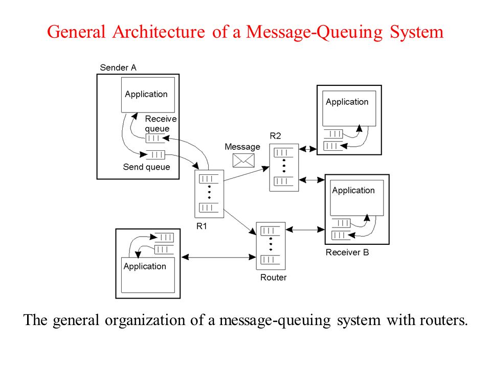
General Architecture of a Message- Queuing System A queue local to the sender is the source queue. A queue in the destination of transfer is the destination queue. A database of queue names to network locations is maintained. Queues are managed by queue managers. Queue managers can operate as relays. –Example: sendmail (port of 25).
..")
104
General Architecture of a Message- Queuing System The relationship between queue-level addressing and network-level addressing.

105
General Architecture of a Message-Queuing System The general organization of a message-queuing system with routers. 2-29
106
Message Broker In message-queuing systems, conversions are handled by special nodes in a queuing network, known as message brokers. Observation: Message queuing systems assume a common messaging protocol - all applications agree on the message format (i.e., the structure and data representation). Message broker: Centralized component that takes care of application heterogeneity in a message-queuing system: –Transforms incoming messages to target format, possibly using intermediate representation –May provide subject-based routing capabilities –Acts very much like an application gateway
. Message broker: Centralized component that takes care of application heterogeneity in a message-queuing system: –Transforms incoming messages to target format, possibly using intermediate representation –May provide subject-based routing capabilities –Acts very much like an application gateway.")
107
Message Brokers The general organization of a message broker in a message- queuing system. 2-30

108
Message-Oriented Middleware Essence: Asynchronous persistent communication through the support of middleware-level queues. Queues correspond to buffers at communication servers. Example: IBM WebSphere MQSeries forms part of the WebSphere Business Integration portfolio of products. Designed to help an enterprise accelerate the transformation into an on-demand business. http://www-306.ibm.com/software/integration/mqfamily/ All queues are managed by queue managers. Queue managers are pairwise connected through message channels, which are an abstraction of transport-level connections.

109
Example: IBM MQSeries General organization of IBM's MQSeries message-queuing system. 2-31

110
IBM MQSeries Application-specific messages are put into, and removed from queues. Queues always reside under the regime of a queue manager. Processes can put messages only in local queues, or through an RPC mechanism. A message channel is a unidirectional, reliable connection between a sending and a receiving queue manager. MQSeries provides mechanisms to automatically start message channel agents (MCAs) when messages arrive, or to have a receiver to set up a channel. Any network of queue managers can be created; routes are set up manually (system administration). Routing: By using logical names, in combination with name resolution to local queues, it is possible to put a message in a remote queue.
 when messages arrive, or to have a receiver to set up a channel. Any network of queue managers can be created; routes are set up manually (system administration). Routing: By using logical names, in combination with name resolution to local queues, it is possible to put a message in a remote queue..")
111
Channels Some attributes associated with message channel agents. AttributeDescription Transport typeDetermines the transport protocol to be used FIFO deliveryIndicates that messages are to be delivered in the order they are sent Message lengthMaximum length of a single message Setup retry count Specifies maximum number of retries to start up the remote MCA Delivery retriesMaximum times MCA will try to put received message into queue

112
IBM MQSeries Message transfer –Messages are transferred between queues. –Message transfer between queues at different processes requires a channel. –At each endpoint of a channel is a message channel agent. –Message channel agents are responsible for: Setting up channels using lower-level network communication facilities (e.g., TCP/IP) (Un)wrapping messages from/in transport-level packets Sending/receiving packets
 (Un)wrapping messages from/in transport-level packets Sending/receiving packets.")
113
Message Transfer The general organization of an MQSeries queuing network using routing tables and aliases.

114
Message Transfer Primitives (programming interface) available in an IBM MQSeries MQI (Message Queue Interface) PrimitiveDescription MQopenOpen a (possibly remote) queue MQcloseClose a queue MQputPut a message into an opened queue MQgetGet a message from a (local) queue
 available in an IBM MQSeries MQI (Message Queue Interface) PrimitiveDescription MQopenOpen a (possibly remote) queue MQcloseClose a queue MQputPut a message into an opened queue MQgetGet a message from a (local) queue")
115
Stream-Oriented Communication A distributed system should offer to exchange time-dependent information such as audio and video streams. –Support for continuous media –Streams in distributed systems –Stream management

116
Continuous Media Observation: All communication facilities discussed so far are essentially based on a discrete, that is time-independent exchange of information. Continuous media: Characterized by the fact that values are time dependent: –Audio –Video –Animations –Sensor data (temperature, pressure, etc.)
.")
117
Stream Transmission modes: Different timing guarantees with respect to data transfer: –Asynchronous: There are no timing constraints on when the data is to be delivered. –Synchronous: A maximum end-to-end delay for individual data packets is defined. –Isochronous: It is subject to a maximum and minimum end-to-end delay (bounded jitter).
..")
118
Stream Definition: A (continuous) data stream is a connection- oriented communication facility that supports isochronous data transmission A complex stream consists of several related simple streams, called substreams. Stream types –A simple stream consists of only a single sequence of data, e.g., audio or video. –A complex stream consists of several related simple streams, called substreams, e.g., stereo audio or combination audio/video The substreams in a complex stream is often required to synchronize. –A movie stream consists of a single video stream, two sound streams, and one subtitle stream.

119
Stream Some common stream characteristics –Streams can be set up between two processes at different machines, or directly between two different devices. Combinations are possible as well. –Streams are unidirectional. –Often, either the sink and/or source is wrapping around a device/hardware (e.g., camera, CD device, TV monitor, dedicated storage) –There is generally a single source, and one or more sinks. If there are multiple sinks, the data stream is multicast to several receivers.
 –There is generally a single source, and one or more sinks. If there are multiple sinks, the data stream is multicast to several receivers..")
120
Data Stream Setting up a stream between two processes across a network.

121
Data Stream Setting up a stream directly between two devices. 2-35.2

122
Data Stream An example of multicasting a stream to several receivers.

123
Streams and QoS The main problem with multicast streaming is when the receivers have different requirements with respect to the quality of the stream. The stream should be configured with filters that adjust the quality of an incoming stream differently for outgoing streams. Essence: Streams are all about timely delivery of data. How to specify this Quality of Service (QoS)? –Make distinction between specification and implementation of QoS. –There is no single best model for QoS. –Flow specification: Use a token-bucket model and express QoS in that model
. –Make distinction between specification and implementation of QoS. –There is no single best model for QoS. –Flow specification: Use a token-bucket model and express QoS in that model.")
124
Specifying QoS A flow specification. Characteristics of the InputService Required maximum data unit size (bytes) Token bucket rate (bytes/sec) Toke bucket size (bytes) Maximum transmission rate (bytes/sec) Loss sensitivity (bytes) Loss interval ( sec) Burst loss sensitivity (data units) Minimum delay noticed ( sec) Maximum delay variation ( sec) Quality of guarantee
 Token bucket rate (bytes/sec) Toke bucket size (bytes) Maximum transmission rate (bytes/sec) Loss sensitivity (bytes) Loss interval ( sec) Burst loss sensitivity (data units) Minimum delay noticed ( sec) Maximum delay variation ( sec) Quality of guarantee.")
125
Specifying QoS The principle of a token bucket algorithm.

126
Implementing QoS Problem: QoS specifications translate to resource reservations in underlying communication system. There is no standard way of (1) QoS specs, (2) describing resources, (3) mapping specs to reservations. Approach: Use Resource reSerVation Protocol (RSVP) as first attempt.
 QoS specs, (2) describing resources, (3) mapping specs to reservations. Approach: Use Resource reSerVation Protocol (RSVP) as first attempt..")
127
Setting Up a Stream The Resource reSerVation Protocol (RSVP) is a transport-level control protocol for enabling resource reservations in network routers. –Senders in RSVP provide a flow specification. –An RSVP process store the specification. –The receiver initiate the request and set the parameters for the specification. –The RSVP process passes the request to the admission control to see of the resources are available and the permission. –If these two tests succeed, resources can be reserved. The resource reservation is highly dependent on the data link layer and the specification is translated to the QoS parameters that data link layer could understand.

128
Setting Up a Stream The basic organization of RSVP for resource reservation in a distributed system.

129
Stream Synchronization Problem: Given a complex stream, how do you keep the different substreams in synch? Example: Think of playing out two channels, that together form stereo sound. Difference should be less than 20 - 30 µsec! Alternative: multiplex all substreams into a single stream, and demultiplex at the receiver. Synchronization is handled at multiplexing/demultiplexing point (MPEG).
..")
130
Synchronization Mechanisms The principle of explicit synchronization on the level data units.

131
Synchronization Mechanisms The principle of synchronization as supported by high-level interfaces. 2-41

Similar presentations


>")

 2007 Prentice-Hall, Inc. All rights reserved. 0-13-239227-5 DISTRIBUTED SYSTEMS.>")


 Layers, interfaces, and protocols in the OSI model. 2-1 Physical: voltage, transmission rate, mechanical,>")


 Computer Science Division.>")


>")


